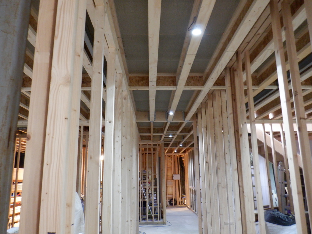
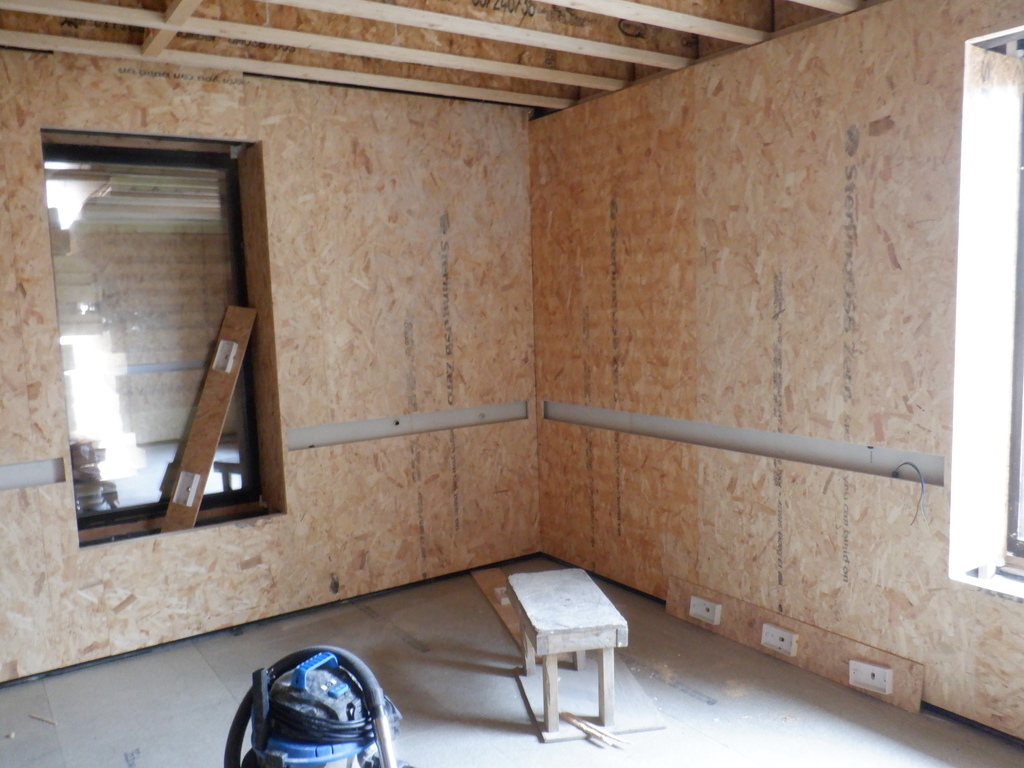
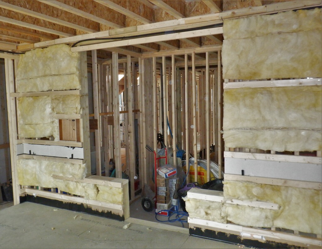
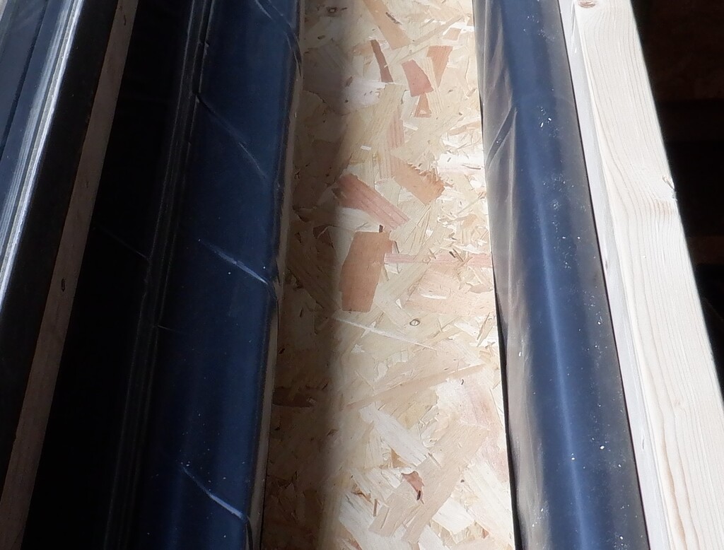
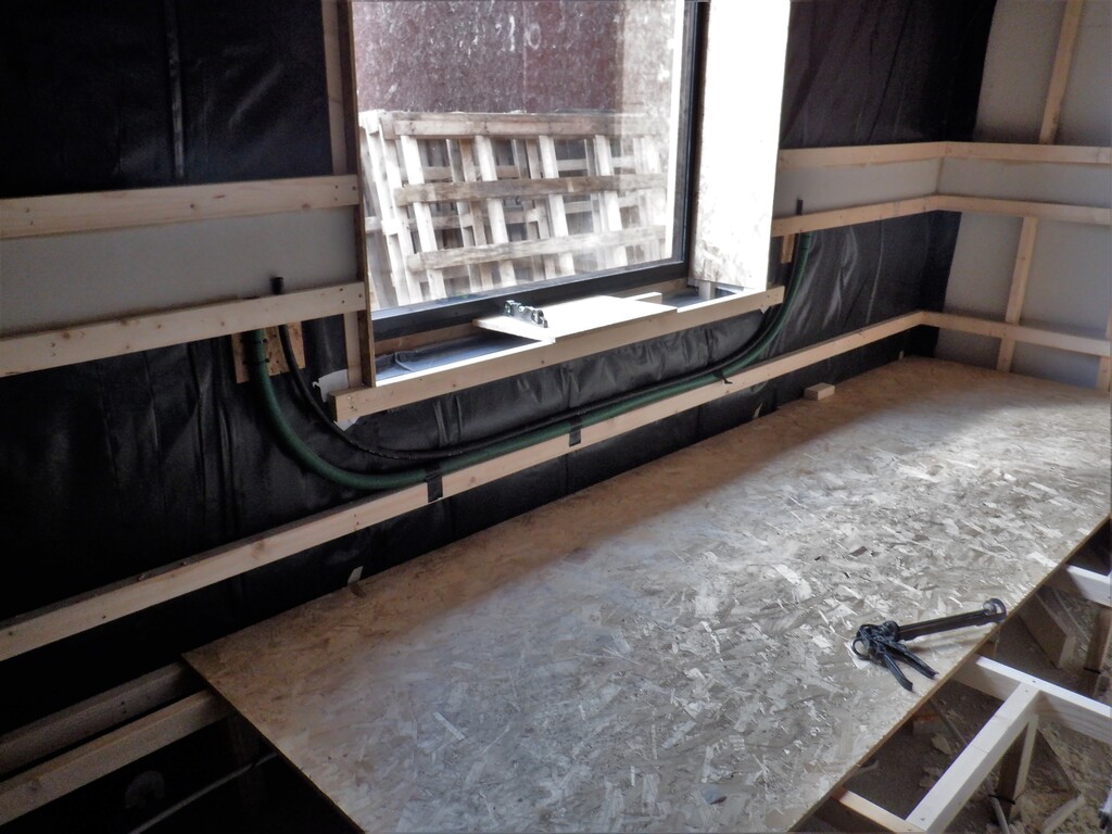
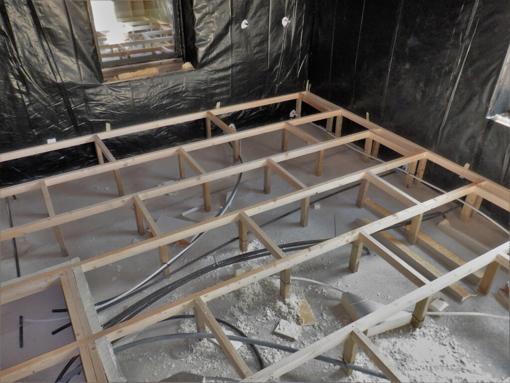
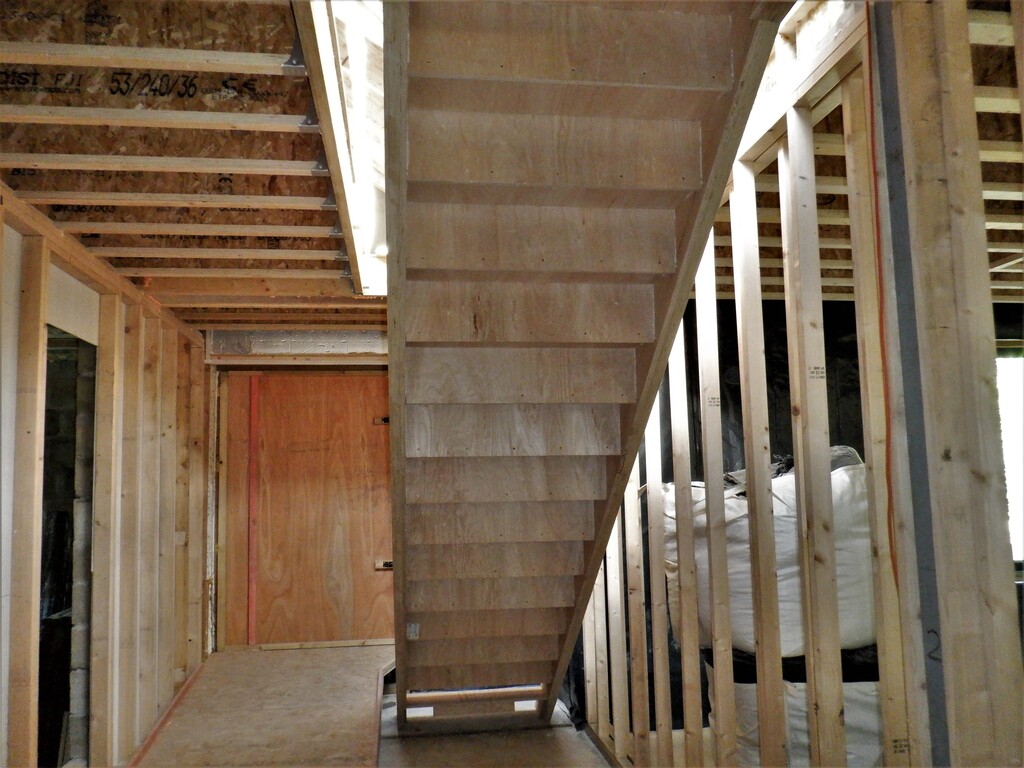
One of the first jobs was to move the existing electricity control board from over beside the window and position it out of the way on the dividing wall between this room and Bedroom Three and reconnect some of the electric cables so they were all out of the way before we could fill in the walls with rock wool and cover it up with the vapour barrier. We also did some extra lighting for our hallways, see Installed Lighting Along Hallways. We then started preparing the Utility Room to be created with all its equipment, pipes, valves, pumps, tanks etc. that will serve the house and one of these items was to create an air outlet vent that will allow the exhausted air to escape the house and we did this by chopping our way through the 200mm thick foam insulation near the ceiling and near the left side of the “E” wall as you stand inside the room. The hole we made was the full width between two wall legs, some 550mm wide and a height of 600mm, reaching the cement board outer skin layer where we sliced a 450mm wide by 500mm high hole through the 10mm thick board. We had some stainless steel woven mesh (left-over from replacing our filter in the rain water filtration system), the mesh is woven with fine wire and has 2mm holes which should stop almost all insects and animals from entering the dangerous zone of a fast spinning blades of the air fan. We used some MS Polymer black glue to attach the mesh to the inside surface of the cement board and held it in place using a plastic covered piece of OSB board with clamps to keep it firmly pressed tight while the glue cured.
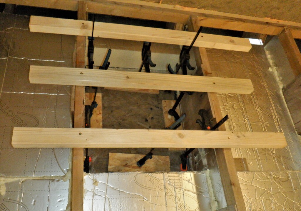
Gluing-the-HVAC-exit-vent-mesh
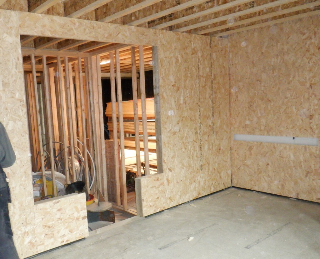
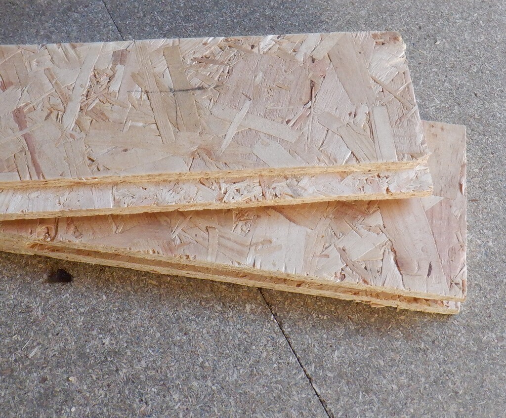
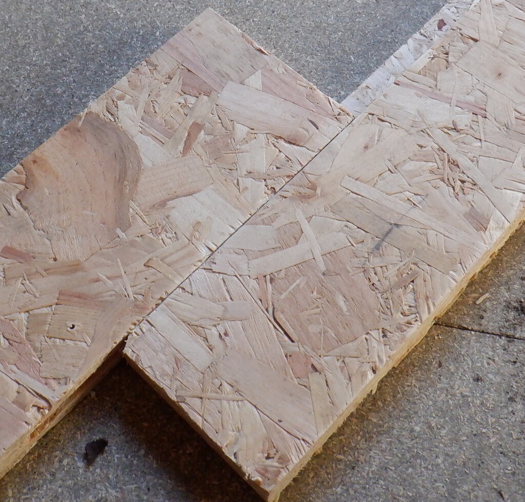
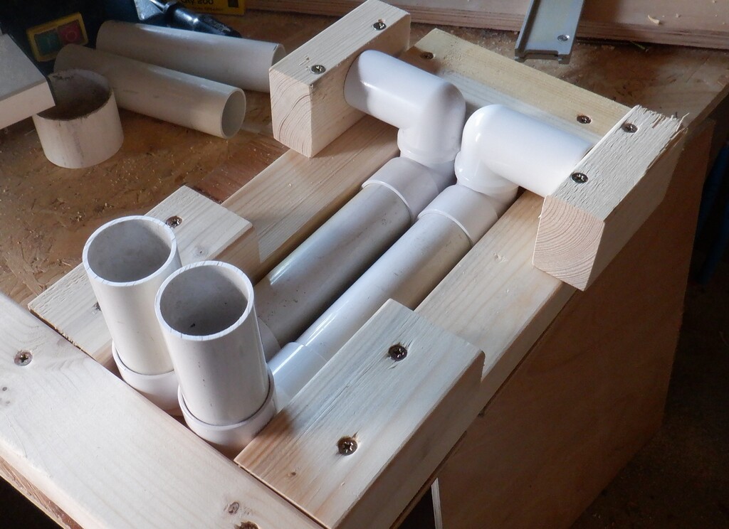
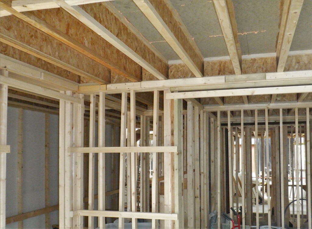
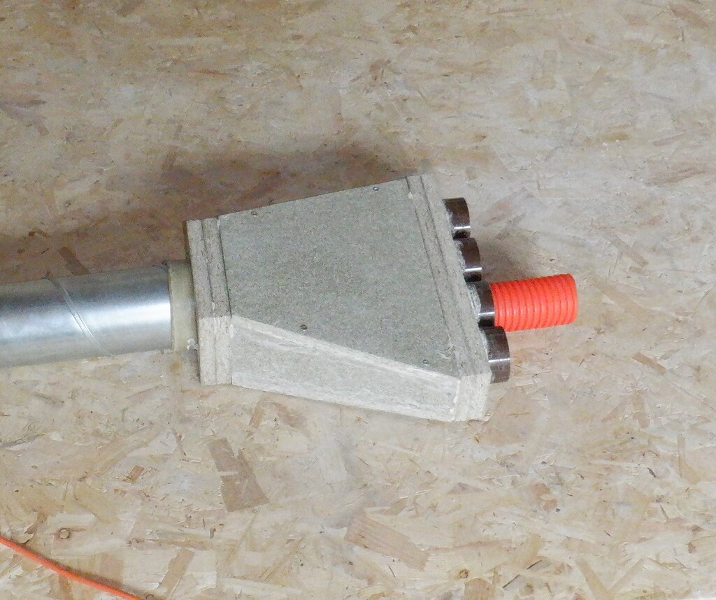
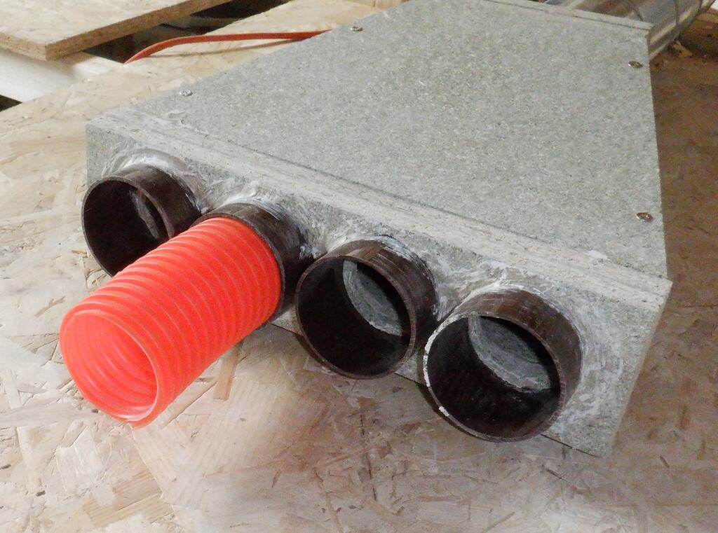
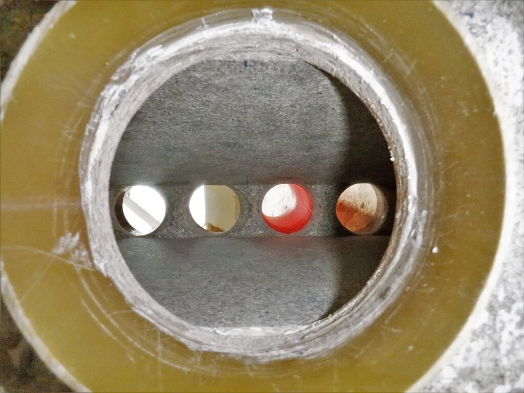
Next, we took some of our left-over 18mm floorboard chipboard material and created a box that will form a large square duct that will help guide the air out of the building. It measures 450mm by 500mm to match the hole through the cement board and put on a ring of 50mm wide strip to provide a larger surface area to bond to the outer perimeter of the wire mesh. The whole box extends well beyond the thickness of the wall so we have options to how much we need when we connect the rest of the ducting and fan later on. Talking about the fan, got one of our new 300mm diameter fans and temporarily seated it inside the new vent hole and powered it up. We did some test runs with different air flow rates and went outside to listen to how noisy it was. We even got out our sound level analyser and took some readings. So at maximum air speeds, we were getting a reading of 63dB at a distance of about 2metres and 65dB and 68dB using different settings on the analyser, representing different patterns of sound pressure and frequencies. The background noise at the time was 40dB, it wasn’t very windy at the time. These figures are quite loud but this was for the maximum possible speed and the sheer power of the fan is that we will only need that kind of air flow rate during the very hottest times of the day in the middle of Summer. Most of the time, the fan will be running much more slowly and we think that it will be about 50dB which is a quiet murmuring noise that fades away when we moved some 5 metres away like the front door or out in the Loke.
Oh yes, just to make clear, the outside layer of Larch timber was still there, the air was escaping through the gaps between all the planks and it seems to be working very well. It gives us the benefit of having somewhere for the exhaust house air to escape but not having a ugly large metal grill visible.
So upon the good test results of running the fan, we proceeded to glue the wooden box ducting into place and filled around the edges with more foam boards, using PU spray foam to stick the whole lot together.
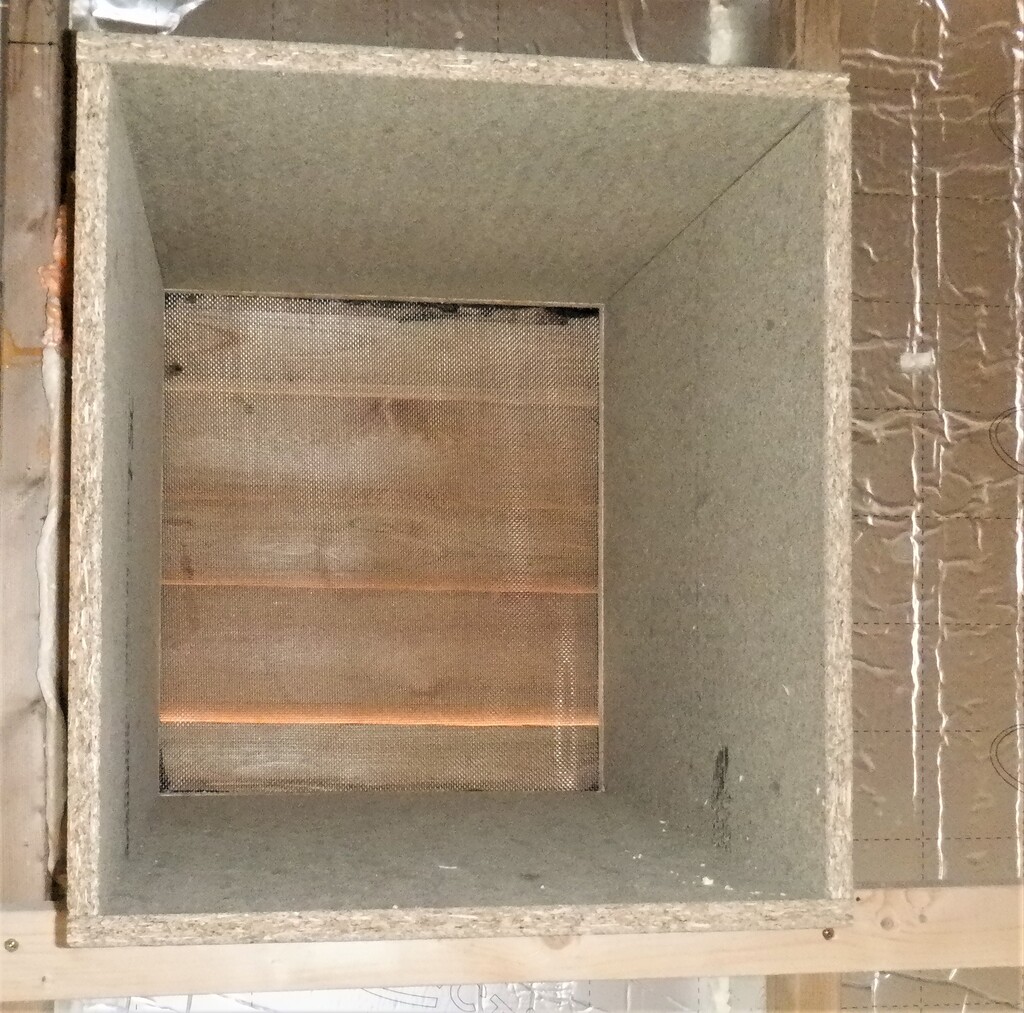
HVAC-Exit-vent-1
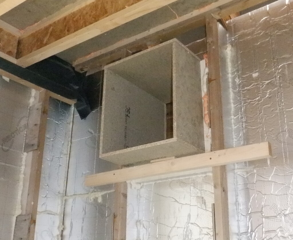
HVAC-Exit-vent-2
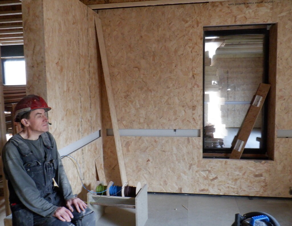
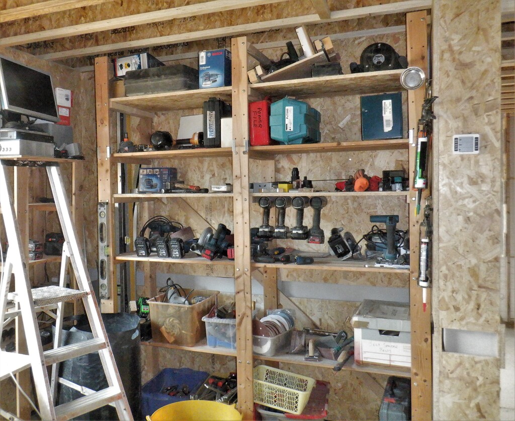
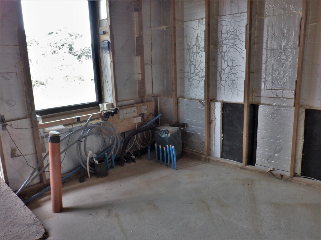
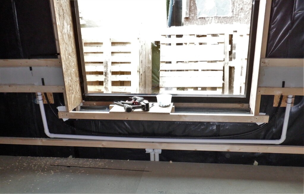
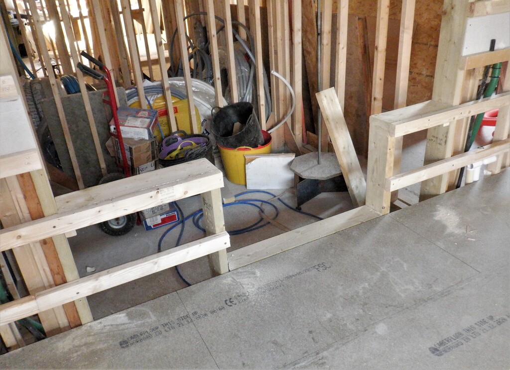
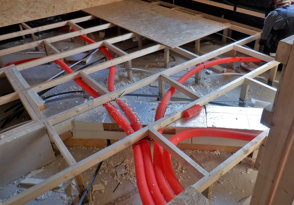
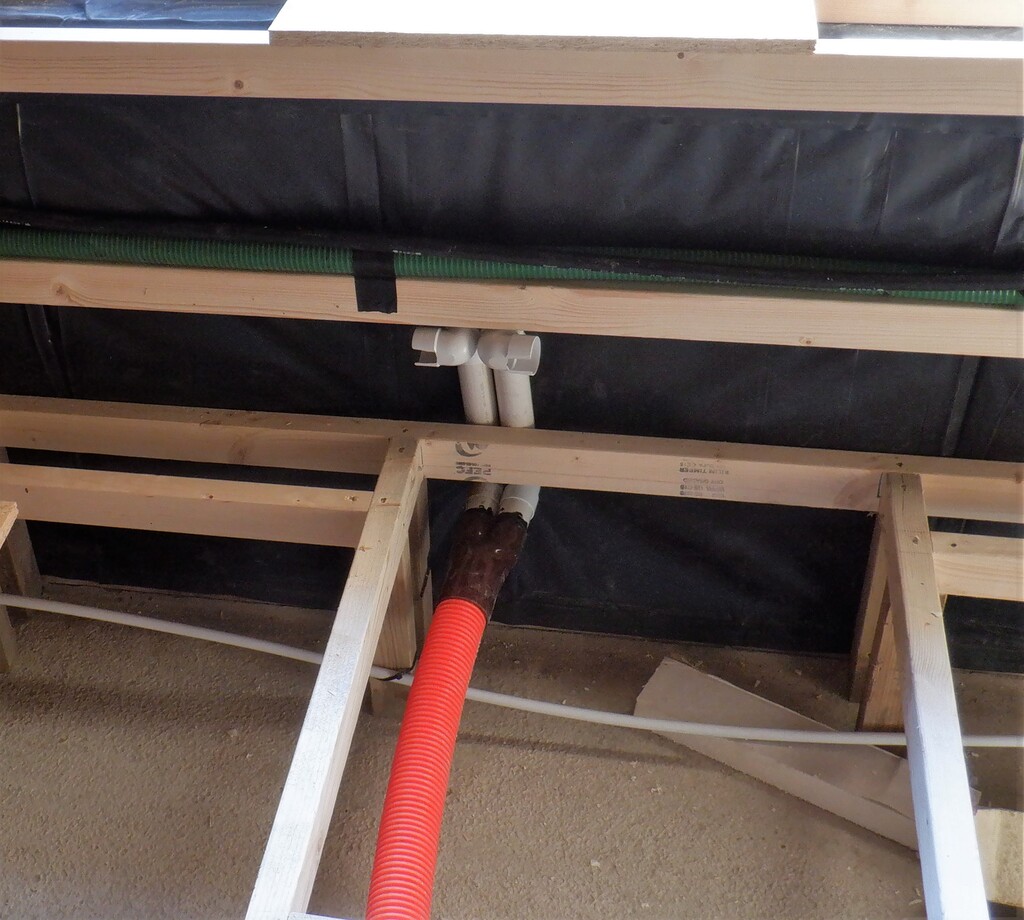
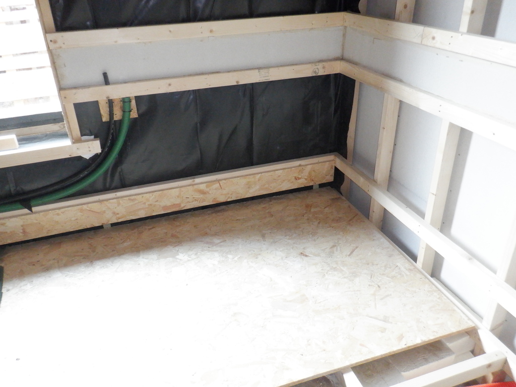
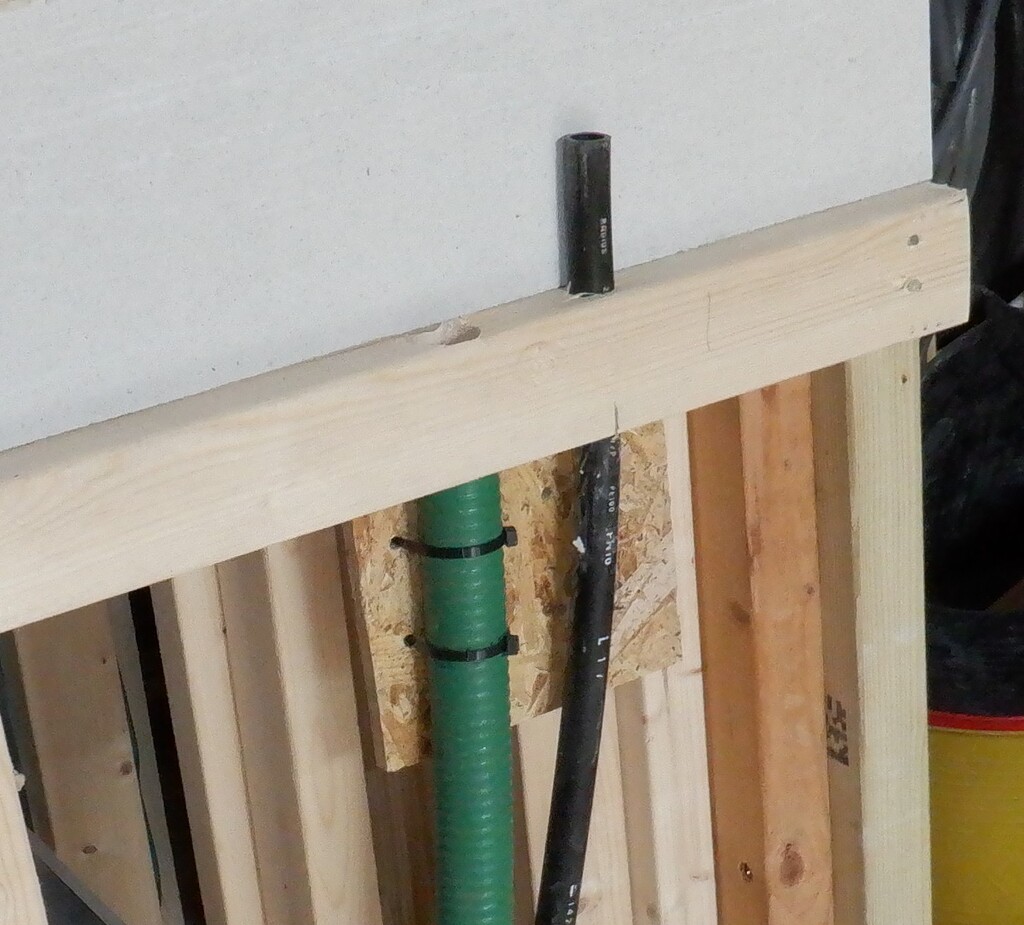
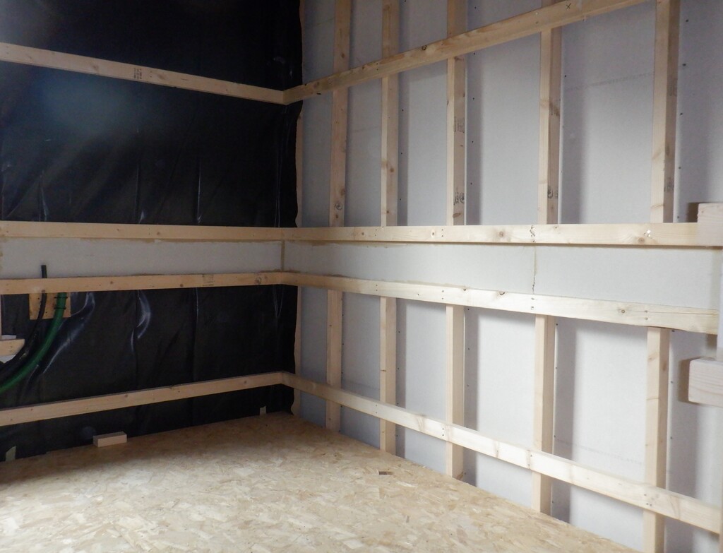
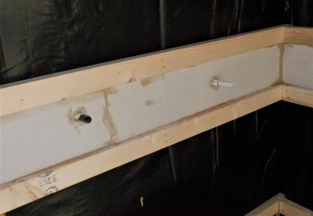
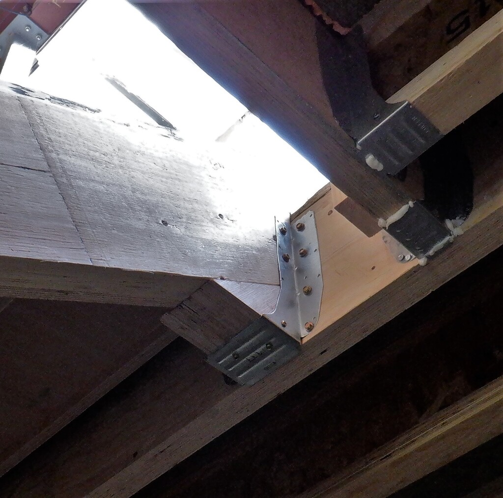
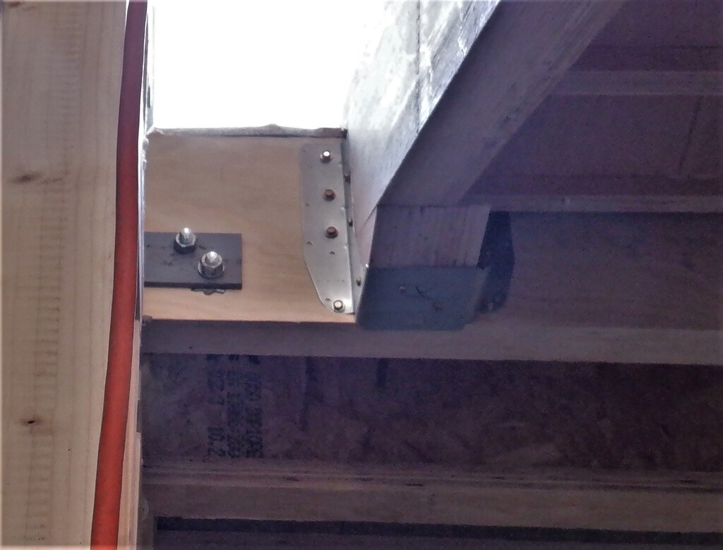
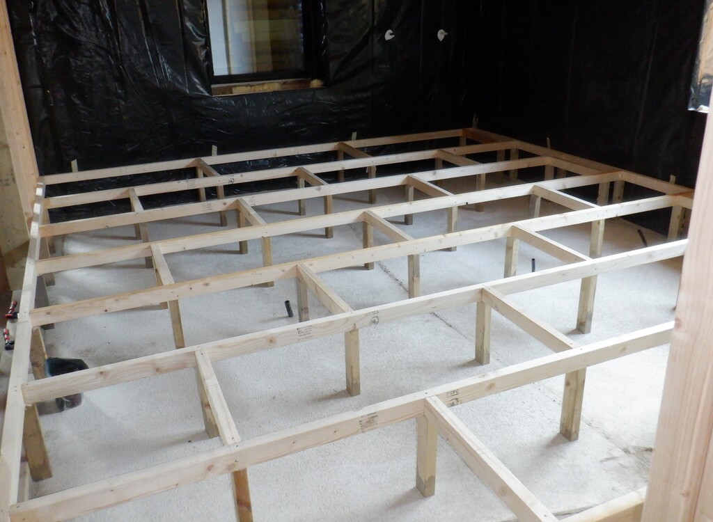
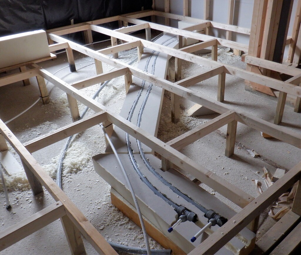
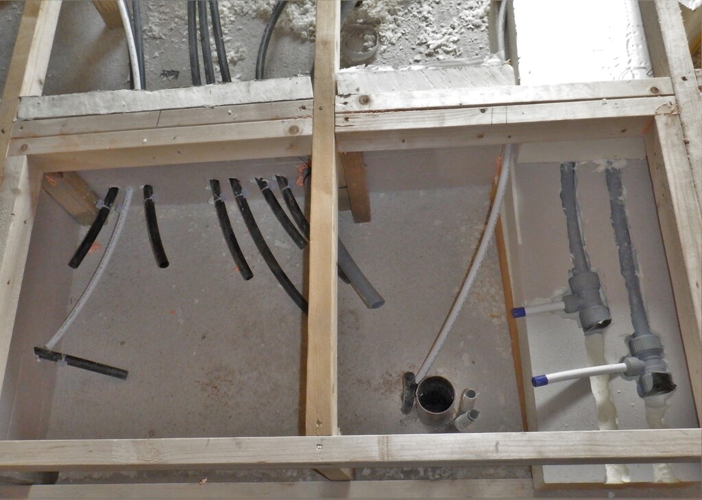
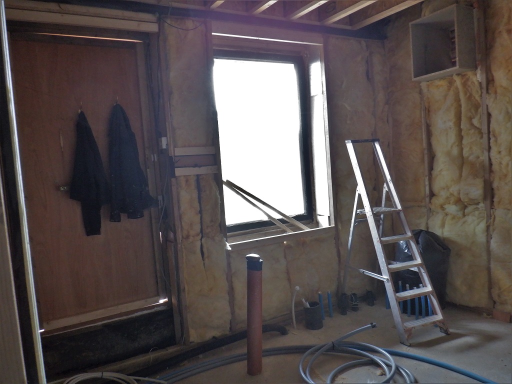
The next job was to insert a long awaited conduit that needed to go from the concrete floor level and all the way up to the Eves, to provide a water irrigation supply for any hanging plants etc. We positioned this conduit near the copper water pipe already installed some weeks ago. There were a couple of other conduits that we also extended and positioned so they were poking out into the room, these were the mains socket in the wall and a couple of underground connections too. Another little task was to screw and glue a vertical CLS post in the corner, the E-F corner to provide a mounting leg for the wall boards when they go up later.
Because the Utility Room has lots of cupboards, a worktop and the door and window too, this meant that there was virtually no where to put sockets and other switches etc. so we decided that we didn’t need to employ the same design of creating a Utility Channel running around the whole room. It is a bit ironic not having one of these channels, called a Utility Channel, in our Utility Room! Oh well. We did realise that we would like a switch beside the Side Door entrance so we could activate the lights or trigger the garage doors to open if we were going that way, so we embedded two short CLS pieces between the wall legs that is sandwiched by the door and window, to form a pseudo Utility Channel. Oh yes, We remembered to insert another piece of conduit that went down to the concrete!
Another preparation task was to go around and plane off all the little sticking edges of the plywood that formed the wall leg structure, there are three of these plywood pieces for each leg and some of them are proud of the leg itself and we need it to be all smooth and ready for the wall boards to go up next week.
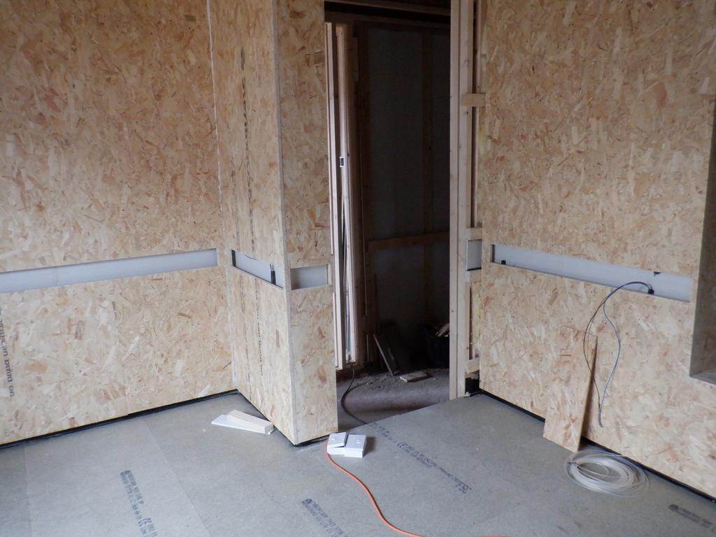
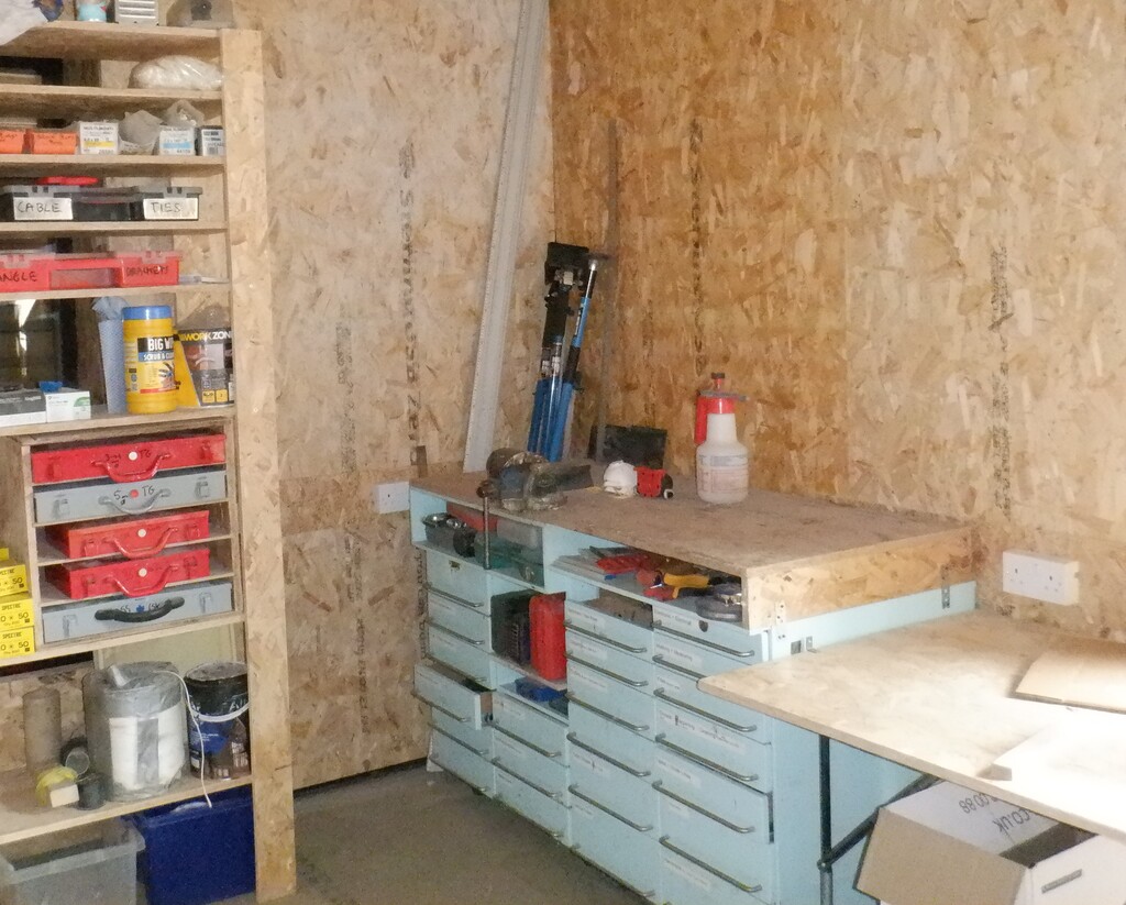
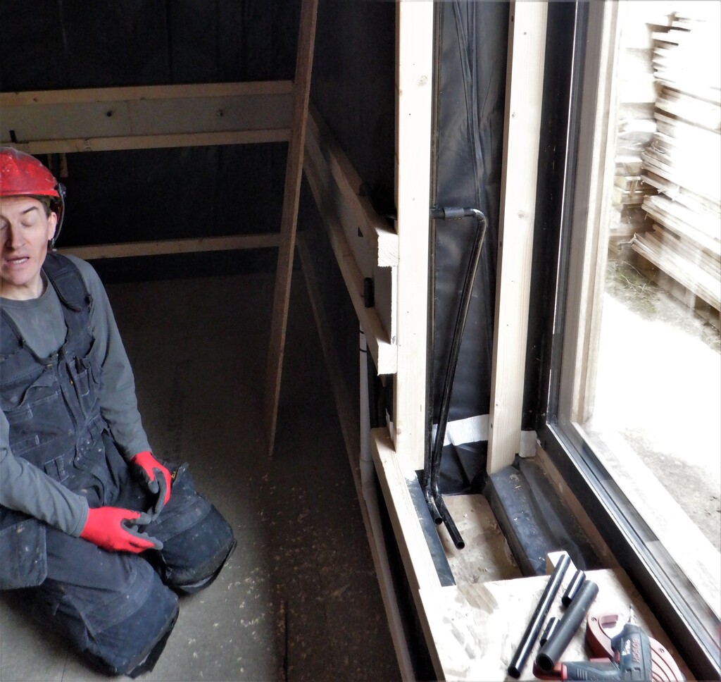
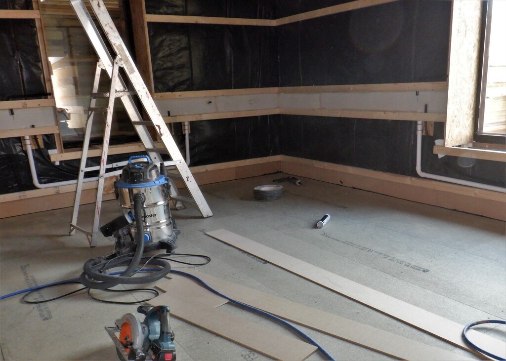
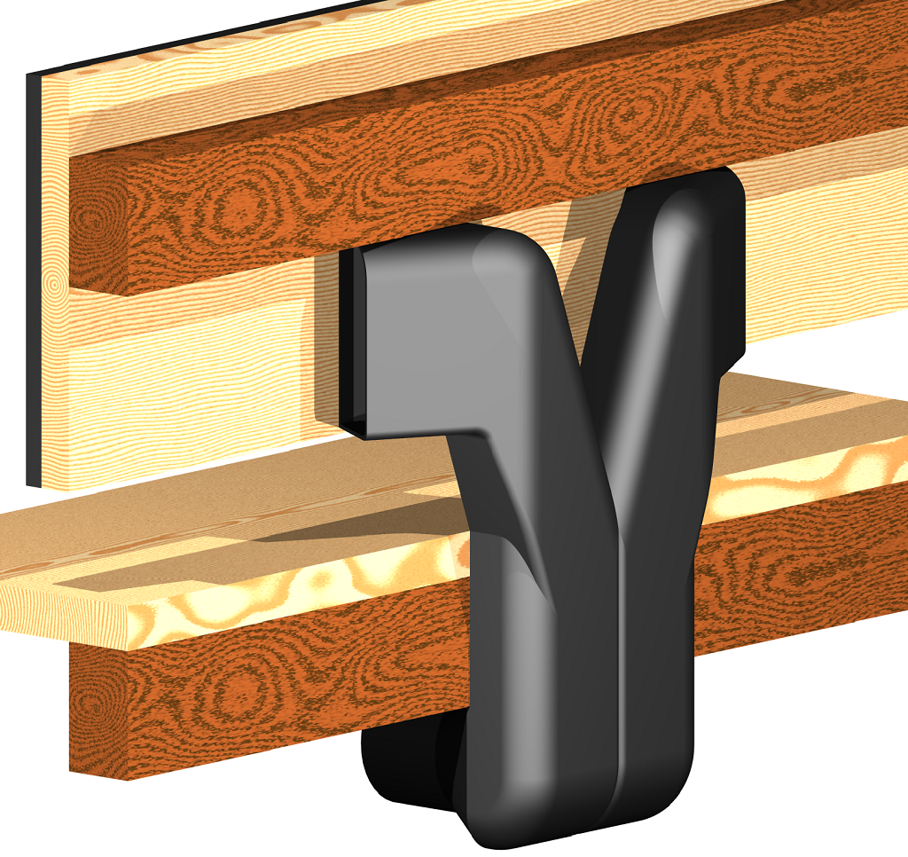
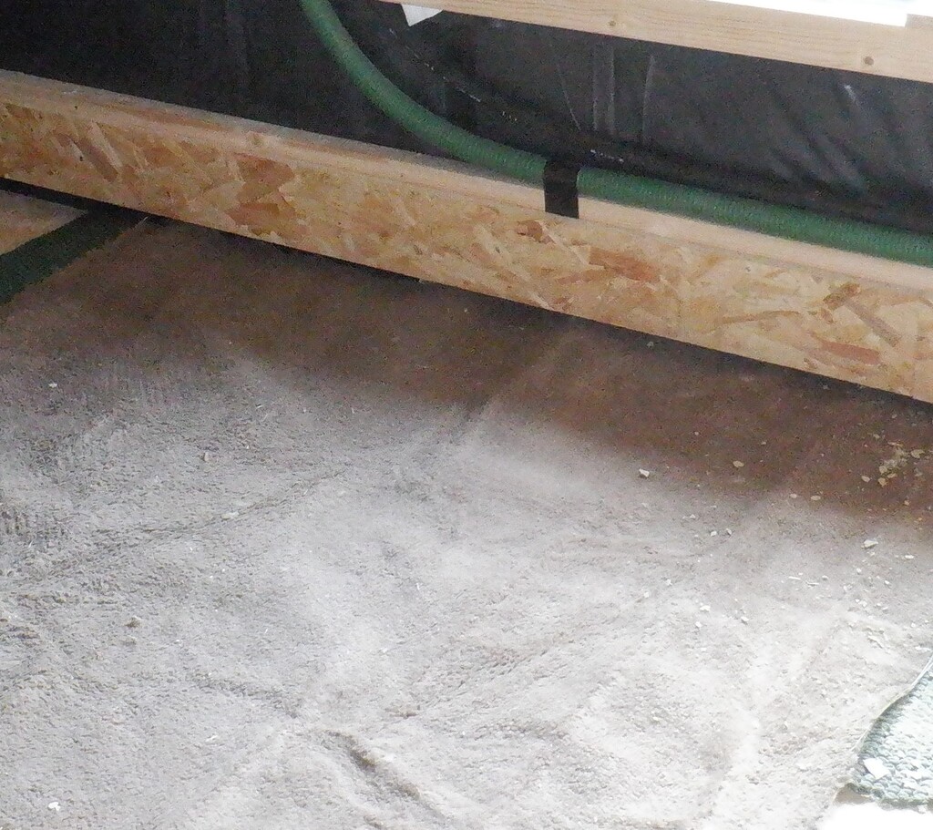
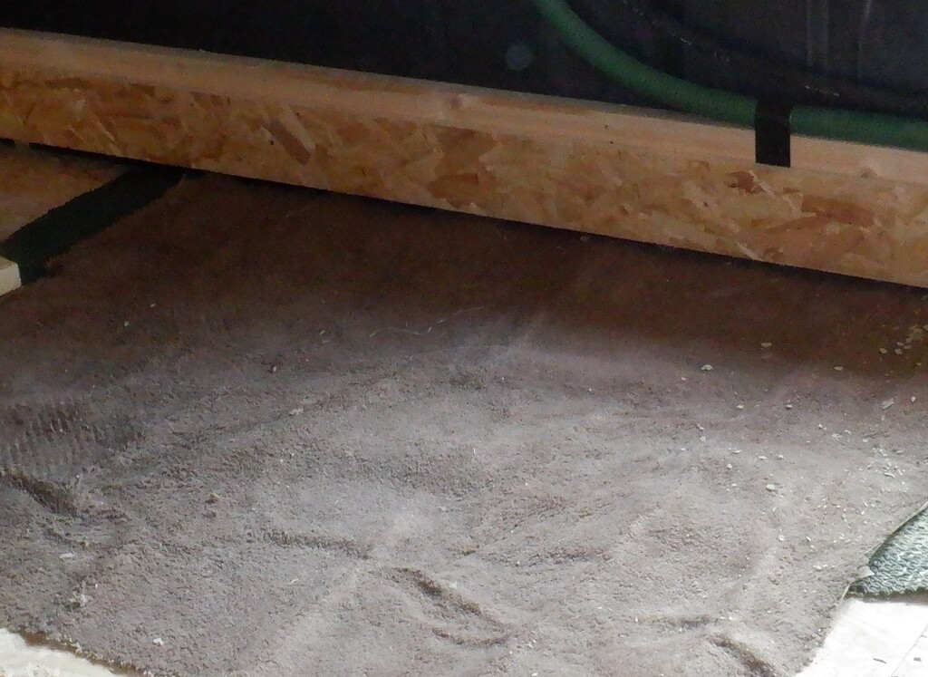
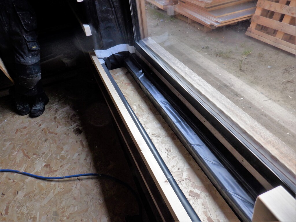
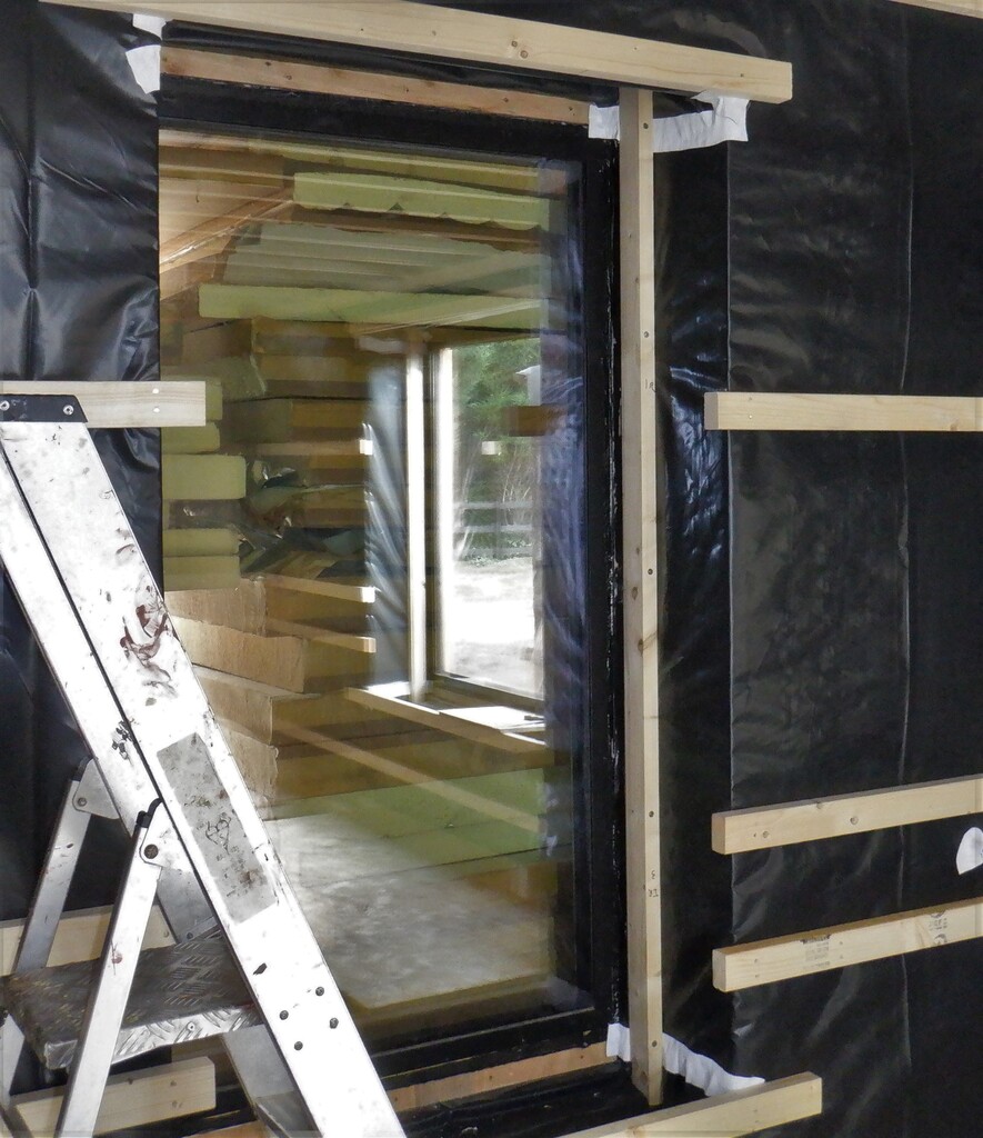
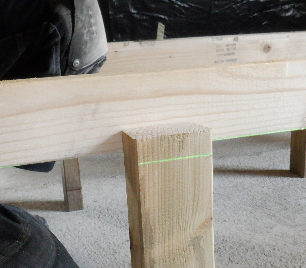
Another job that needed doing was measuring and making horizontal rails for the bottom and top of the window and the top of the door too. These rails are the exact position that defines the height and hole of the window at 500mm from the floorboards and 2200mm at the top, also the same for the door too. But we don’t have the same utility rails that other rooms have, we had to fit them inside the framework instead and there is already pieces of CLS timber in place but only approximately at the correct position. We needed to create a special piece for the window, a 45mm to 47mm high piece for the bottom rail and a more even 30mm piece at the top. The doorway was easier and a normal 63mm piece went in straight. Well perhaps not easier after all, because we discovered that our temporary door was too tall and hit this new framework piece. This led us to having to deal with the door itself next. We took it off and decided that while it is off, we would go ahead and install a new temporary door sill, to make sure that we will get above what will be the new floor surface when we put down the floorboards. We found a piece of “4by2” treated timber, cut it down to 1040mm length, to fit the width of the doorway, levelled it off by using a couple of solid 5mm plastic spacers and a smaller 3mm one in the middle and fixed it into place using three concrete screws plus a heap of MS polymer glue to seal the outside joint to provide some water protection against future rain floods.
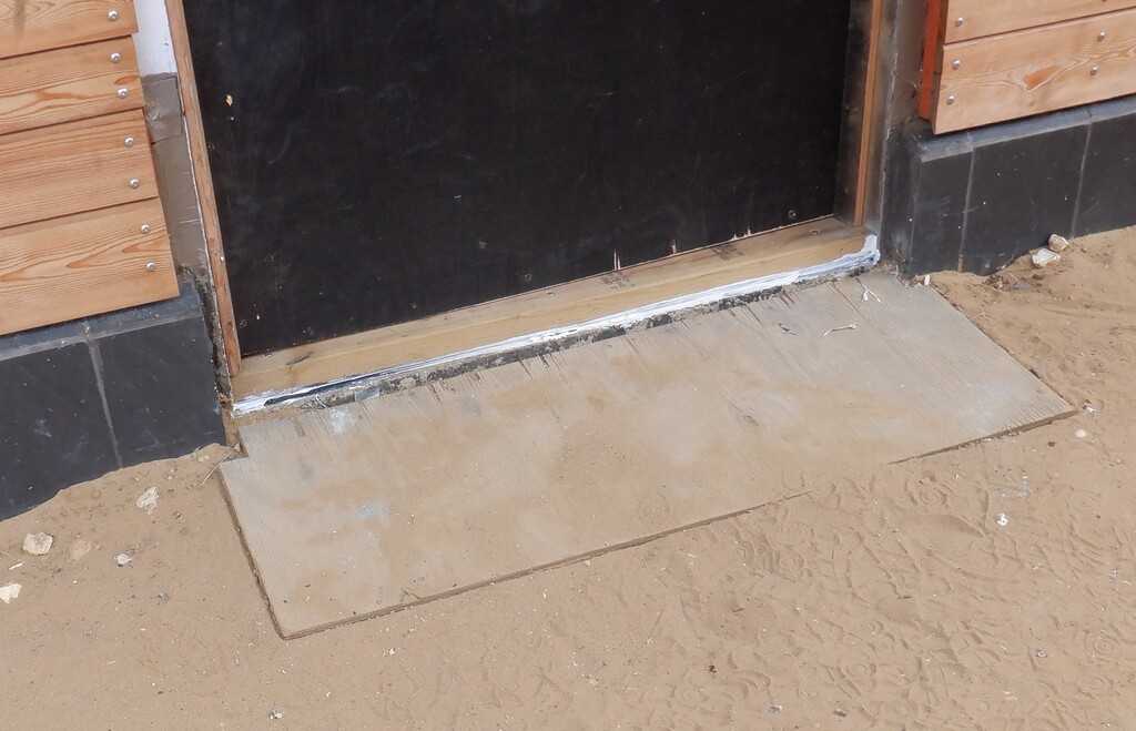
Temporary-side-door-sill
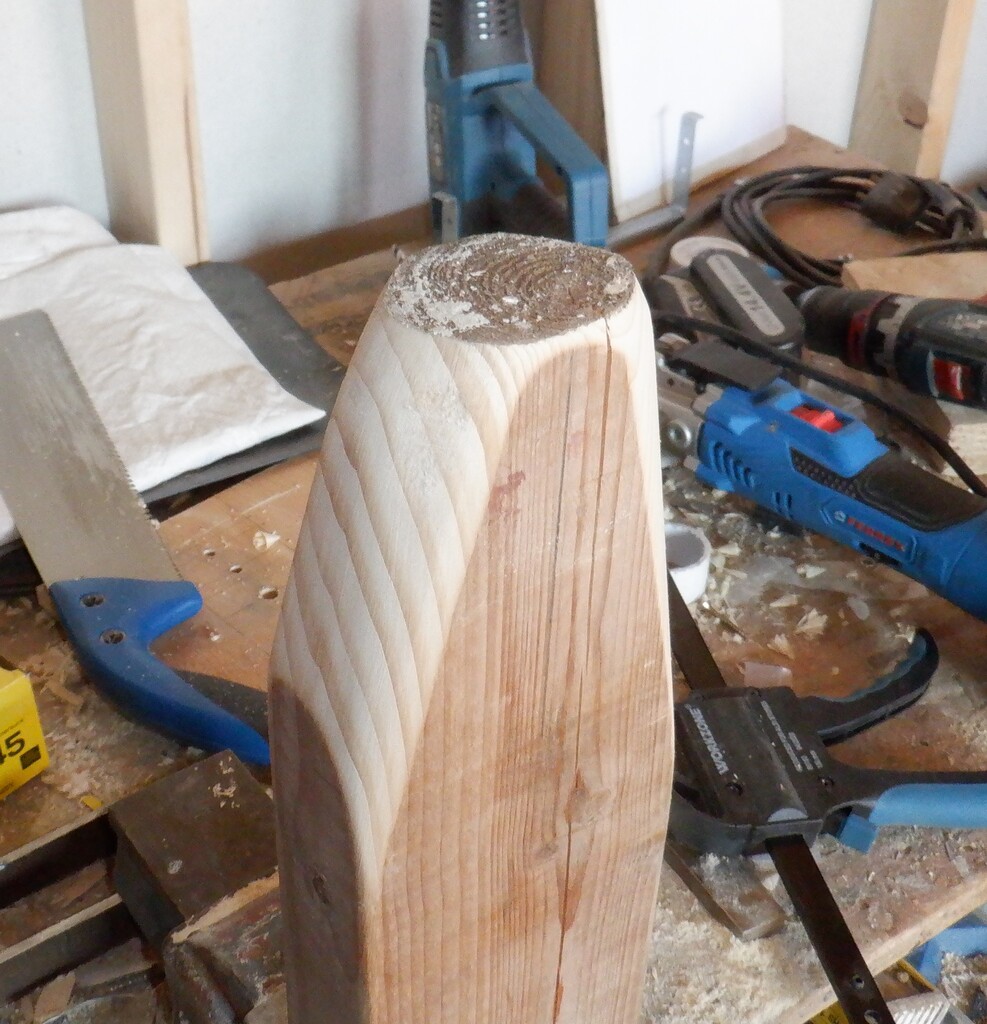
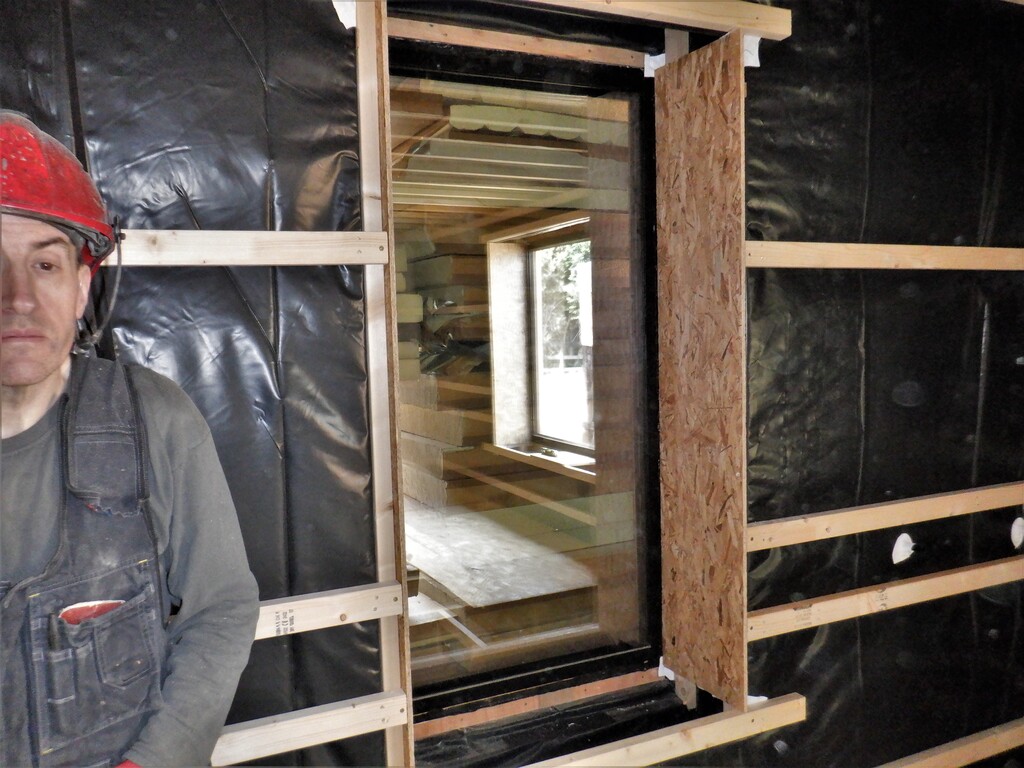
Now that we had the new sill in place, we could measure the amount of material we would have to remove at the bottom of the door, some 45mm in total. We put in an replacement CLS frame to ensure the bottom of the door was still reasonably stiff. Then we chopped off 10mm off the top to clear that new upper rail and then put the door back. We did have to do further adjustments by running the planer across the bottom edge as the door turned out not to be exactly square but since it is only a temporary door, we kludged it to get it to fit without scraping!!
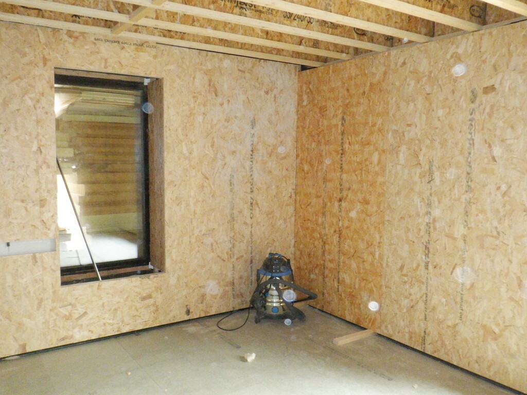
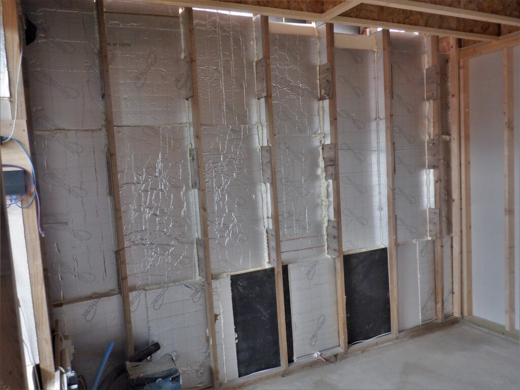
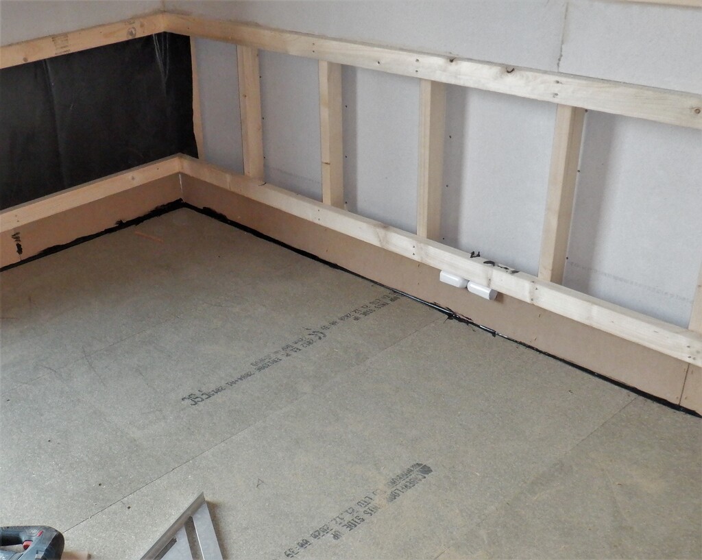
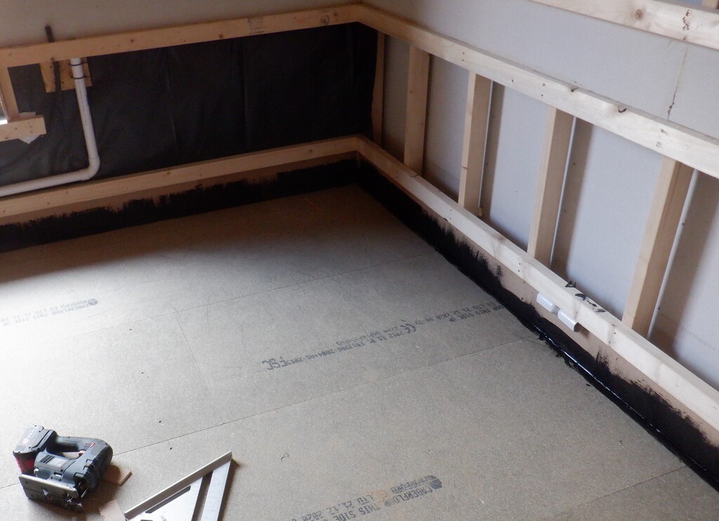
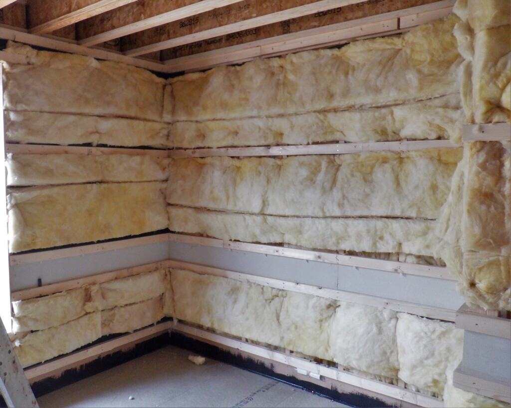
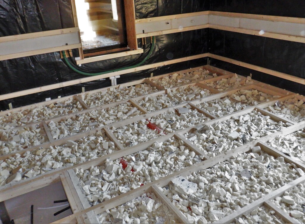
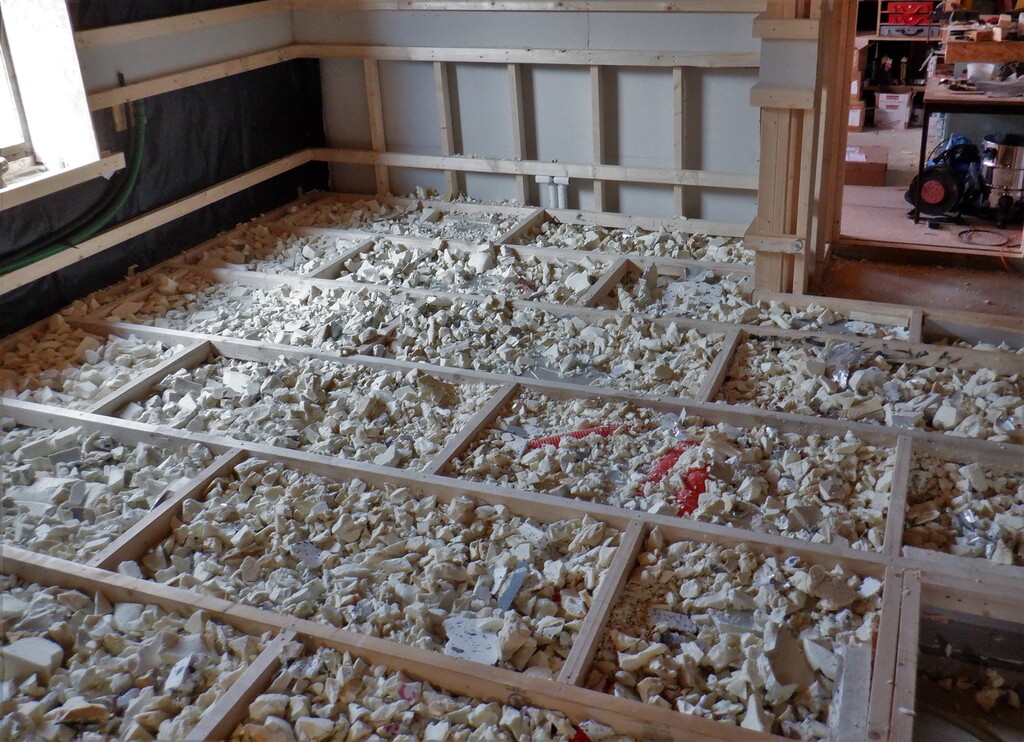
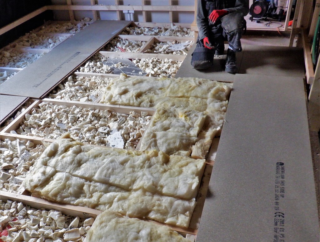
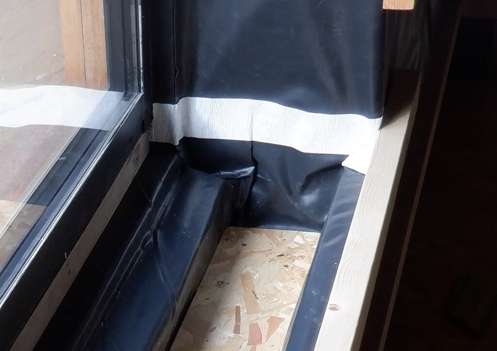
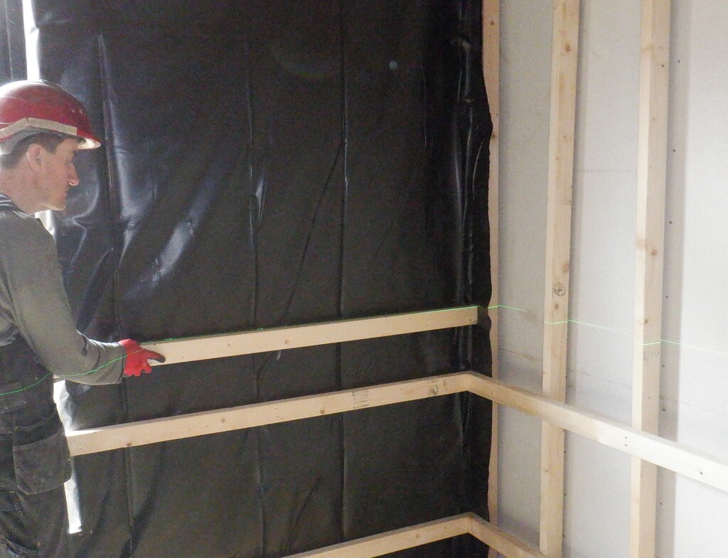
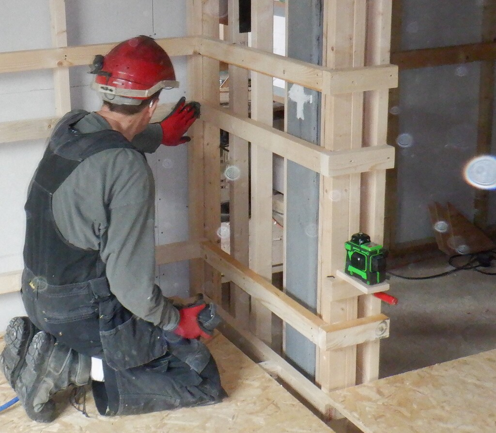
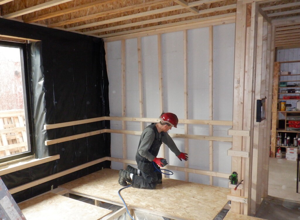
Finally, we were in the position to do the next stage of filling in the walls with glass wool and the plastic vapour barrier membrane. We scrubbed the aged timber surfaces along the bottom, applied a line of the butyl heavy duty double sided sticky tape along the bottom edge, around the window and along the top edges too. Where there were a plastic layer already, we used acrylic sticky tape instead. Next, we unrolled and cut up lengths of glass wool pieces, 100mm thick stuff for the lower half and longer pieces of 200mm thick stuff for the upper sections. We filled in the corners and around the door and window so everything is now filled in.
Fibre-in-utility-walls-1
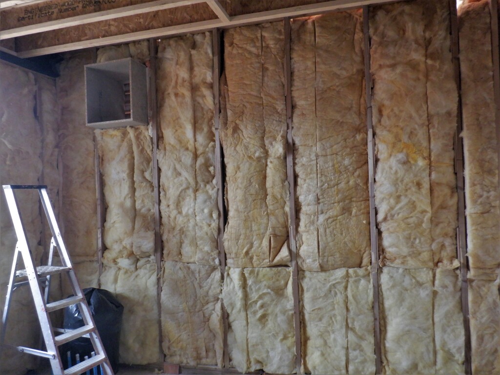
Fibre-in-utility-walls-2
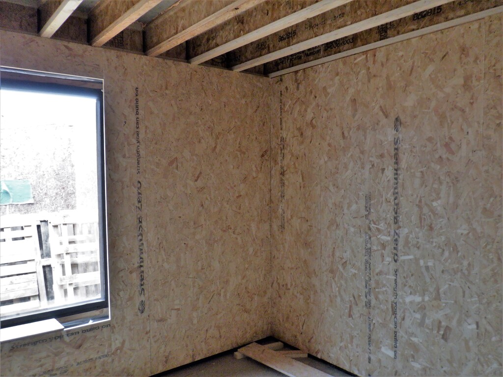
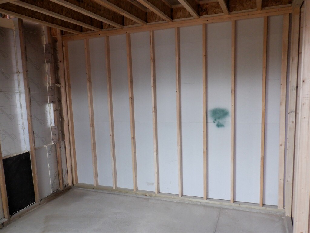
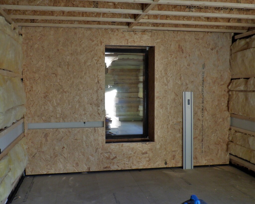
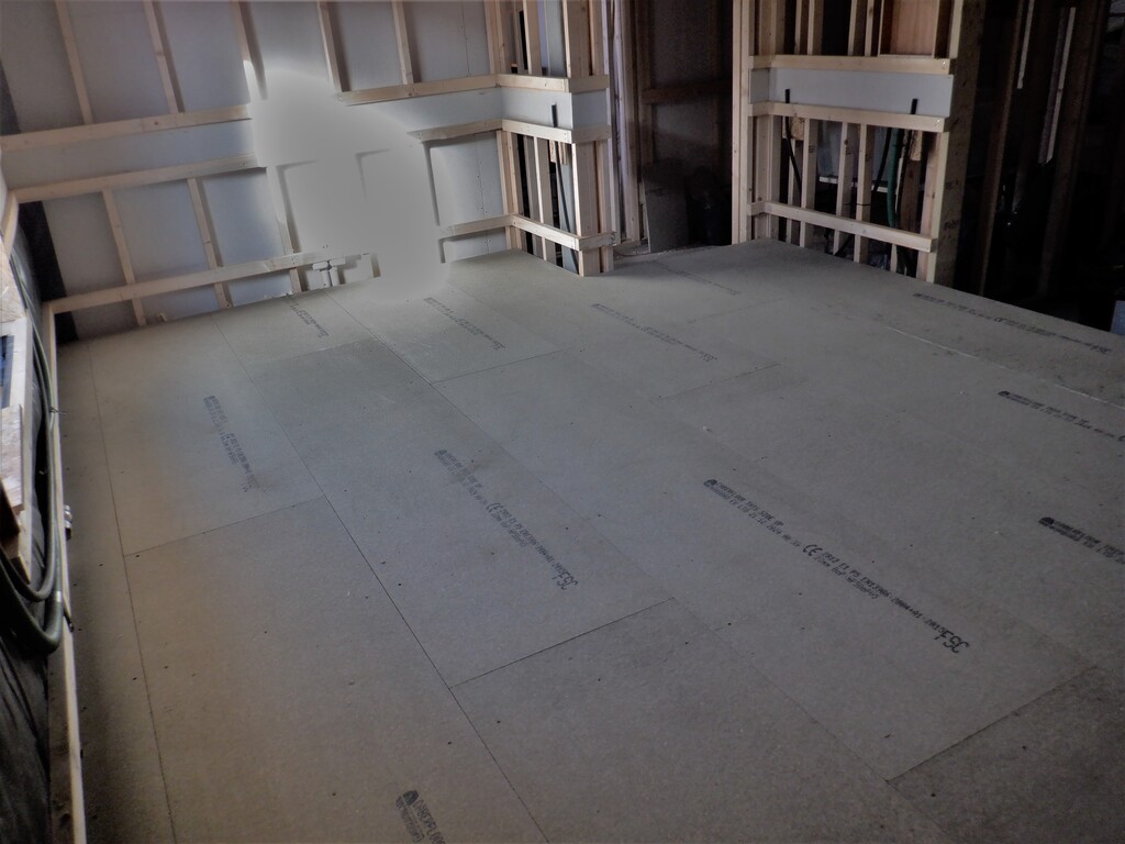
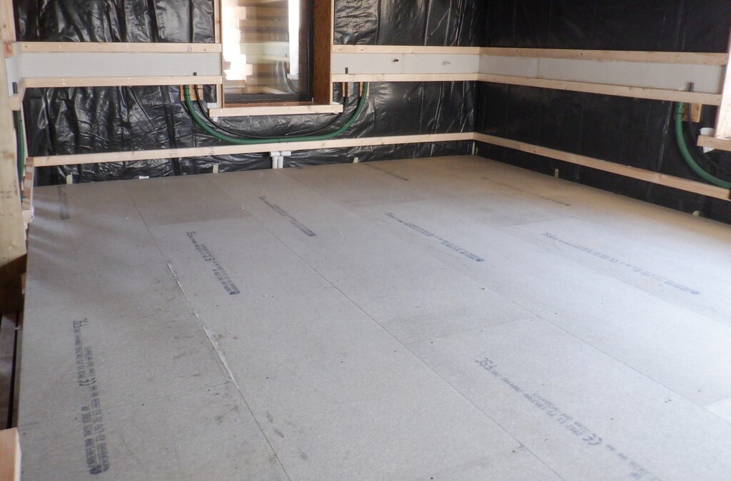
After that, we put on sheets of plastic to encapsulate the yukky glass wool stuff and provide a vapour barrier to stop condensation from forming in the body of the wooden walls and hence avoid potential rot problems.
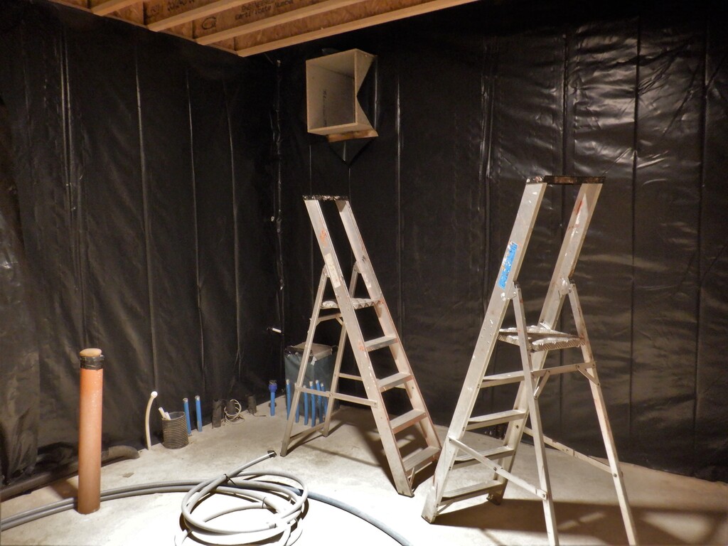
Utitlity-walls-with-vapour-membrane-1
Utitlity-walls-with-vapour-membrane-2
We now have finished covering up the walls, just a little bit to finish off like sealing around the air duct and various conduits sticking out, plus finishing off the window and door too. Then we can install a layer of plasterboard to cover up this plastic to provide a fire resistant barrier and then we can start on building the internal “cupboards” that will contain the equipment that provides the utilities and services for the house.