Author: Shaun

  • Started Installing Joists for First Floor

    We have started the process of installing the joists for the First Floor. The last two and half days were spent on several tasks, like for example, marking out on top of all the structural walls running from the front to back of the house, with 400mm centres for each joist. We used our new green laser line generator to produce lovely straight alignments right across the whole building and then using this reference line to mark off all the 400mm centres on each wall supporting a joist.
    Next we set up the saw station outside under our front porch, the only place where we had enough room to accommodate eleven metres of I-Beams and kept as dry as possible between sessions. Then put on an extension fence on two further trestles and additional roller support stands further out along the line in and out of the saw station.

    Started Installing Joists for First Floor

    Joist-cutting-setup

    Started Installing Joists for First Floor

    Joist-plan


    Then, the real work starts, we decided to start from the Great Room end of the house over Bedroom 1, we measured the distance from the Bedroom 1 wall interfacing with the Great Room, to the wall flanking the little hallway to Bedroom 2. This revealed that it was 6840mm for the first six joists, labelled 24 through to 19, arriving on the first of the twin 63mm think walls and these joist are the 53mm width flanges as they don’t have to deal with the Gallery sticking out the Great Room. Joist 18, the first of the 96mm flanges is a full 8metres long and then joist 17 and 16, also 96mm flanges were sliced at 8300mm long. The saw station worked very well, with only a slight adjustment needed to increase the spacing to allow the wider flanges into the station.
    Started Installing Joists for First Floor

    Sawing-a-96mm-joist


    We carried each one across our driveway and then into our Side door, along the hallway and then sliding (just!) into Bedroom 1’s entrance, to climb up the stepladder and hoist the joist up on top of the Great Room wall and rotating around a bit before climbing up the second stepladder to dump the other end up on the En-Suite wall and finally pulled back until it reached the mini hallway. We collected the joist in a group over near the outside wall because there was a special requirement of making a 110mm diameter hole through the webbing of Joist 18 and Joist 19 to allow the sewage pipework to run from the upstairs toilet shower room. This is a rigid piece of pipework and the joists had to be free to move to allow this insertion to occur (while the other joists were out of the way).
    Started Installing Joists for First Floor

    Plumbing-for-the-upstairs-Toilet


    Using the left-over pieces of the I-Beams, we created a pile of noggings either measuring 347mm or 304mm wide plus a few specials measuring 325mm that fits in between a wide flange and a narrow flange joist. These noggings fills in the spacing between the joists to help anchor and stiffen up the whole joist structure to stop them slipping sideways and falling over under load.
    For the end of this week, we put in a set of noggings and spaced out the joists evenly, for a test run and see how well things look. We didn’t have time to glue or nail them down.
    Started Installing Joists for First Floor

    First-set-of-joists-placed-1

    First-set-of-joists-placed-2

    First-set-of-joists-placed-2


    So we will resume next week and start fixing things down properly and so the First Floor is finally being created – Yippee!

  • Wall and Sign Repaired

    This morning and yesterday were spent on repairing the broken wall and repainting the street sign for our Loke after the delivery lorry with our I-Beams had misjudged things and knocked into the curved brick wall at the entrance of our Loke on the main road.
    Yesterday, we managed to pick up the pieces and glue them back together again using our adhesive PU foam that was specialised to glue building materials. Many bricks were still mortared together in large sections and we carefully put the jigsaw puzzle back in the correct order without having to remove any of the old mortar. The bricks were the ones where it had two large round holes instead of a frog and we slid and wiggled each layer back and stick on the top row back down.

    Wall and Sign Repaired

    Rebuilt-wall


    The old metal street sign had also got disturbed and was in terrible state so we decided to bring that home to give it a complete revamp with fresh metal paint.

    Wall and Sign Repaired

    Old-loke-sign

    We removed the old green vinyl coating, scrubbed and got the aluminium clean and shiny again. This then had a half a dozen thin coats of a green hammer effect metal spray paint and left to dry and cure overnight.
    The new letters, “Smiths Loke” was re-created on the computer, using the British Highways standard font face and adjusted to fit along a metre length of the sign and 150mm high with a white border. The paper print out was stuck to the freshly painted metal with that special spray glue that allows the removal and refixing. Then the border and each letter was very carefully cut by following the lines using a sharp scalpel to leave “holes” where the letters were, ready for several coats of a white metal spray paint.

    Wall and Sign Repaired

    Repainted-sign


    Once this was dry, after lunch today, we took up the new sign and positioning it very slightly higher because the old holes had many missing mortar where the plugs were. Drilling new holes and using mushroom headed stainless steel screws, the new sign was affixed back on the repaired wall.
    Wall and Sign Repaired

    Wall-all-refurbished


    We probably will take down the twin street sign on the opposite side of the Loke and do the same thing again. This sign is starting to peel and it is done at a different time and by a different hand with poor quality letter placement so it would be good to get this sign repaired too and both become a matched pair.

    Wall and Sign Repaired

    Old-loke-sign-Left

  • I-Beams Arrive!

    In the morning we prepared an area to store the beams next to the house.

    The lorry arrived at 1:25pm with the 66 special I-Beams on a open flatbed vehicle, in two packs covered in plastic. The driver thought he could reverse down our Loke and save a lot of effort but after attempting to come in both directions and failed to get enough room to straighten up. In fact, he couldn’t hear the shout to stop and unfortunately bumped into the garden wall of the house flanking the entrance to the Loke and knocked a section down. We excused the driver and we said that we would repair the wall ourselves (we confessed to the house owner who is a nice chap).
    So the lorry parked straight on the main road and we unloaded the I-Beams one by one off the back and placed them into the Loke to minimise the unloading time and then let the driver go off.
    It was 2:50pm at this point, so we had a half an hour rest plus to quench our thirst too!
    Resuming at 3:30pm, we got our trolley loaded up with 22 pieces and started down the Loke. But soon discovered that the dolly module was struggling to get over the little ramp and was creaking and wiggling alarmingly. We put on four more giant clamps to help stiffen up the load points and carefully got over the ramp.
    That was exactly a third of the total and it was clearly overloading things. So we reduced the quantity and put only 15 pieces for the next three trips. The ratchet straps were doing a good job of keeping everything tied down and stopping the load slipping.
    Once we got the load down to our place, we transferred it over to our temporary storage location just inside the fence (we released the wire mesh and rolled it up and pulled out two posts) and place each I-Beams into an ordered piles on two 2by6 planks supported by two concrete blocks.
    After unloading the final 15 I-Beams, we covered it all up with a fresh tarpaulin as the material they supplied was ripped rather badly during the unloading process.

    I-Beams Arrive!

    All-66-beams

    I-Beams Arrive!

    Beams-wrapped-up


    We finished everything at 7:30pm and we were knackered!!

  • Preparing for the Arrival of 66 Timber I-Beams

    Monday is the big day with the arrival of 66 special timber I-Beams, the last three days have been spent preparing for this happy day. So, we adapted our large flat bed trolley to help the job of transferring the very long I-Beams down the Loke from the main road. They come in a range of lengths, the majority being ten metres long but several are eleven metres, some 35feet and weighing up to 66kg each!
    The trolley had a single upright plank mounted on, with a small gap underneath to allow for a ratchet strap to lock down the jumble of I-Beams tight to the trolley when we haul it down the Loke. We estimate that it will take three separate trips to move all the 68 pieces, the total weight being over two tons so we decided to split it into three separate loads.

    Preparing for the Arrival of 66 Timber I-Beams

    Beam-transport-trolley


    Next, we made a little dolly module to help support the other end of the long beams. This module is using two solid castors bolted to another one of our old trusty two by six planks and an extension tower built upwards to bring the level to match the main trolley.
    Preparing for the Arrival of 66 Timber I-Beams

    Beam-transport-dolley


    Because we were on the main road, which is quite busy, we made two alert signs using a couple of our trestles and clamped on to the front face a shiny insulation board with yellow and black stripe tape around the border to divert the traffic away from our Loke entrance to allow us to swing in these massive lengthy objects, walking into the road itself when we take them off the lorry.
    Preparing for the Arrival of 66 Timber I-Beams

    Traffic-blocking-board


    Also during this last week, we constructed a new slicing machine, see Extra Large Sliding Saw and repaired one of the tyres on the large trolley that had developed a leaky valve and we replaced the inner tube. It was a quick leak and we wanted to ensure that the trolley stood up to giving us the proper quality of work without having to pump up the tyre every 10 minutes.

  • Extra Large Sliding Saw

    The other piece of equipment we made while we waited for this day, was to build a special chop saw table to cope with slicing these I-Beams. Their physical size, especially the biggest one is 96mm wide (the flanges) and 240mm high. No standard chop saw, or even mobile saws, have enough depth of cut to cope with that kind of magnitude so we pulled out an old piece of equipment we had made several years ago (see
    Bevel Slicing Machine Repaired
    back in November 2017) and adapted it for our new task. The base board and hinge was removed and a new fixed plate mounted and then two double extension drawer runners were screwed on. Then, one of our old trestle tables was used to build a framework to allow the I-Beams to slide through this module against a straight and square fence. The saw part was then connected to the support table and we now have a smooth sliding saw ready to slice up our I-Beams into the required lengths.

    Extra Large Sliding Saw

    Cross-cut-saw-for-Joists-1

    Extra Large Sliding Saw

    Cross-cut-saw-for-Joists-2

    Extra Large Sliding Saw

    Cross-cut-saw-for-Joists-3


    Next is to prepare the trolley to help transport these I-Beams down our Loke.

  • Installed Dozens of Conduits and Pipes through the External Wall for Future Expansion

    At the beginning of the three weeks waiting for the arrival of our First Floor Joists, we sat down to analyse all requirements of providing connections to the outside world like electricity, data, water and waste services. We looked at the underground situation as well as the Eves too. We wanted to make sure that we had provisions for future ideas and expansions in our garden, swimming lane, patio, lighting and controlling the various gates, lights and other features. All these are the underground connections but for the Eves, we are thinking of more lighting, PIR detectors, temperature probes, sunshine level indicators as well as a watering distribution system for potential hanging baskets etc.

    There are four main types of connection as follows:

    1. Water : Either clean pressurised water or dirty kitchen waste
    2. Low DC voltage : a nominal 48V but perhaps 12V or 24V
    3. Data/Logic : Network transport layer, either ethernet or RS484 balanced lines
    4. Mains 230V supplies : for occasional high powered devices.

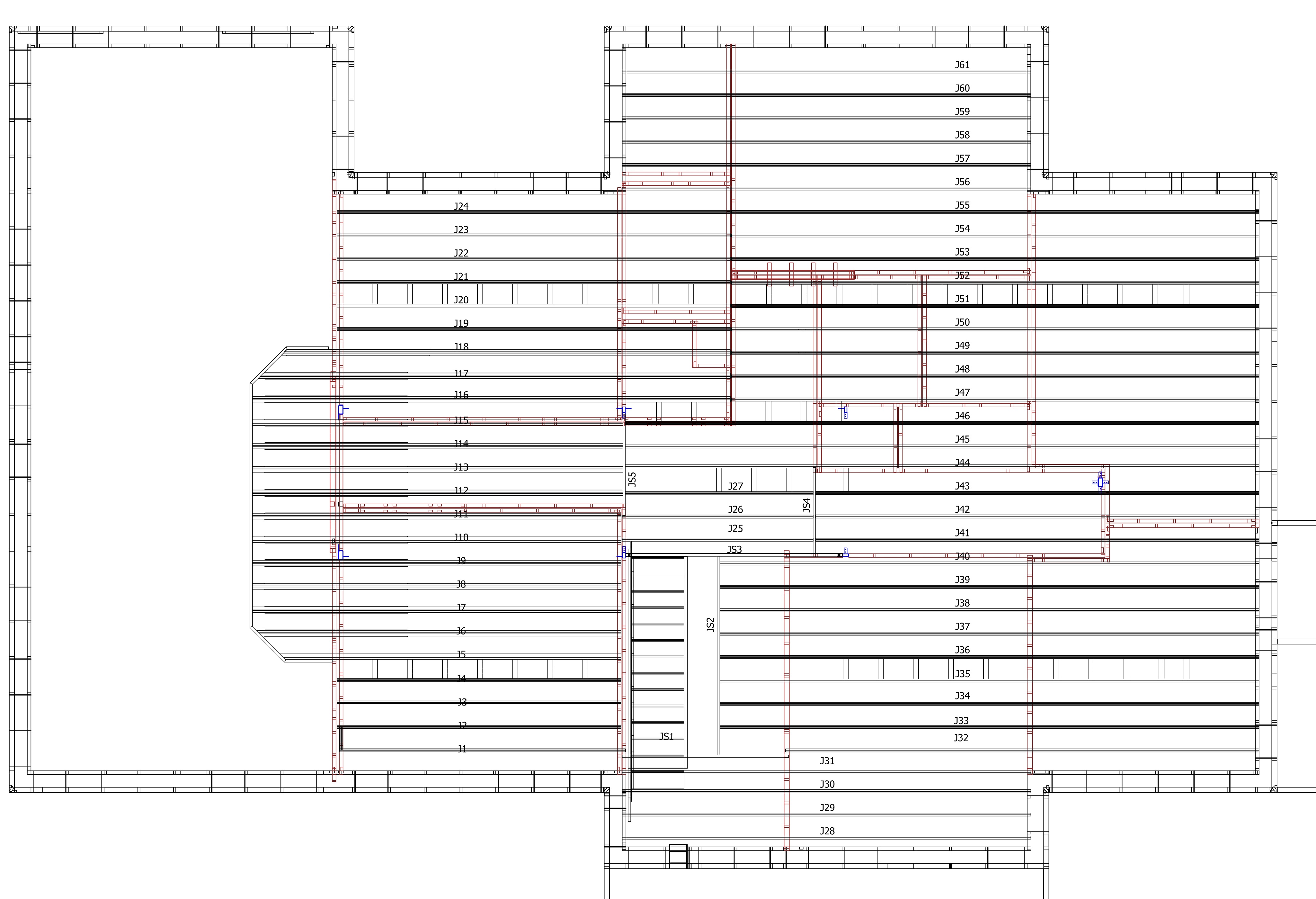
    We we have a total of 63 individual connections that is “punching” through the wall somewhere as follows:
    For the Eves:

    • 19 Low Voltage and Data black 20mm PVC rigid conduits
    • 8 waterpipe black 20mm polyethene conduits (flexible)

    For mid-wall:

    • 3 Mains 230V waterproof sockets
    • 4 water hose quick-lock sockets
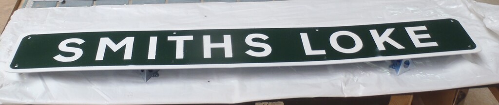
    • 1 letterbox!

    For Underground:

    • 1 kitchen waste 40mm PVC pipe
    • 4 pressurised water in copper / brass 15mm pipe with ½inch female adapter
    • 5 low-pressure irrigation water in the copper / brass pipe adapter
    • 2 circulating water connections to and from the Swimming Lane also in the copper pipe.
    • 10 mains 230V in white PVC conduits
    • 10 low voltage and Data black PVC conduits
    • 9 temperature probes black polyethene conduits

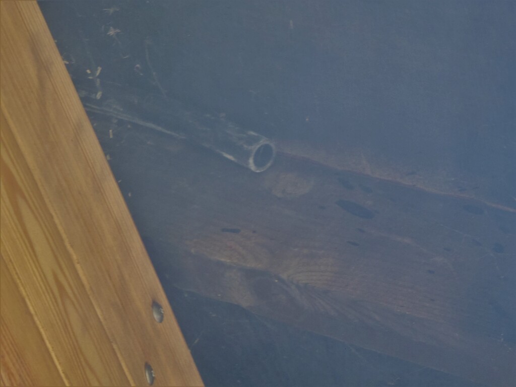
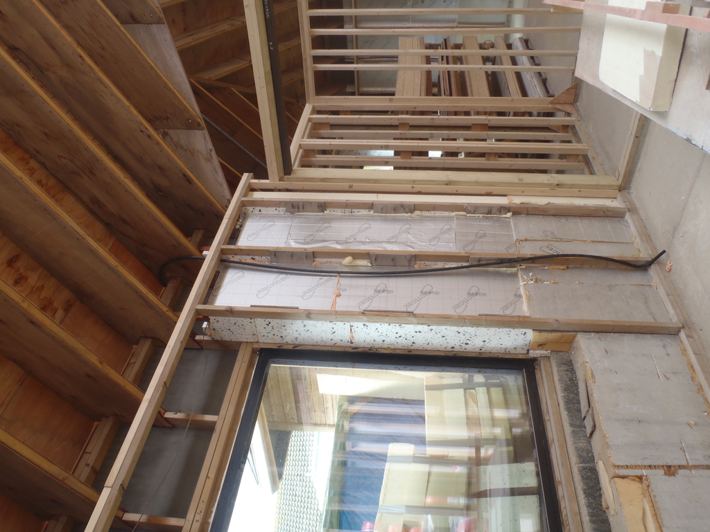
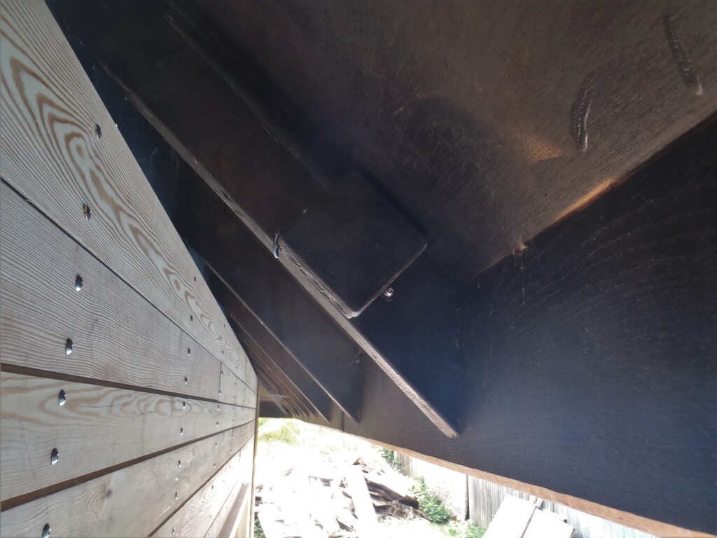
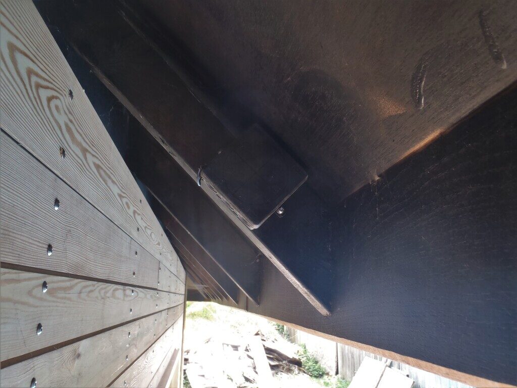
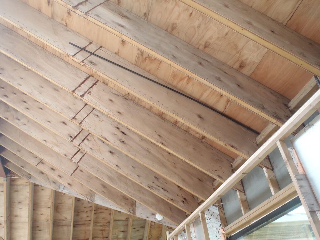
    The first task we tackled was the conduits up to the Eves so we took the polyethene black pipes to act as a conduit for guiding the thin water irrigation tubing and put in a sharp right angle bend at the bottom of the wall, cable tied it to the wooden leg and swept around a more gentle curve to then run along the rafter under the roof boards. After drilling a hole through the cement board, finally poked the other end of the conduit and stopped half way down the Eve, ready for the tubing to go on further to whatever plants are hanging up there.

    Installed Dozens of Conduits and Pipes through the External Wall for Future Expansion

    End-of-a-irrigation-conduit-under-eves

    Installed Dozens of Conduits and Pipes through the External Wall for Future Expansion

    End-of-a-irrigation-conduit-under-the-floor


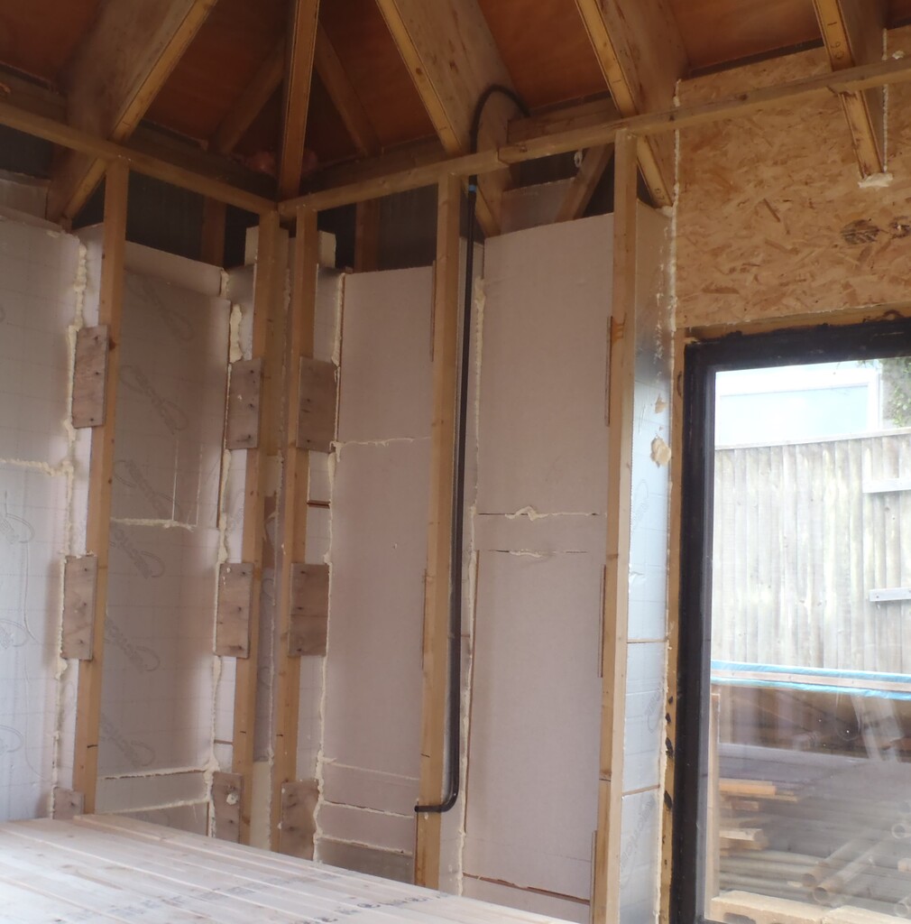
    Next, was the electrical connections and for this type, we used a black rigid PVC pipe that are also 20mm in diameter but much thinner walls. We did not need to bend it as we could provide the access to the cables upstairs in the triangular void, except around the Great Room as the first floor doesn’t extends right across the room. Here we did blast the pipe with our hot air gun and bent it around the jig again to make a doubly bent tubing to make it arrive behind the Utility Channel.
    Installed Dozens of Conduits and Pipes through the External Wall for Future Expansion

    Conduit-box-behinf-eves
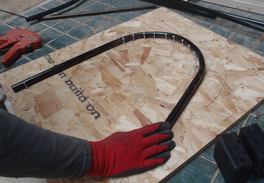
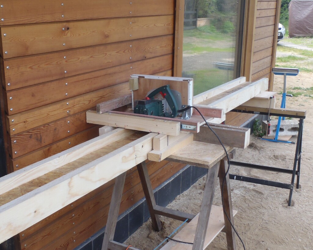
    Installed Dozens of Conduits and Pipes through the External Wall for Future Expansion

    Conduit-bending-jig

    Installed Dozens of Conduits and Pipes through the External Wall for Future Expansion

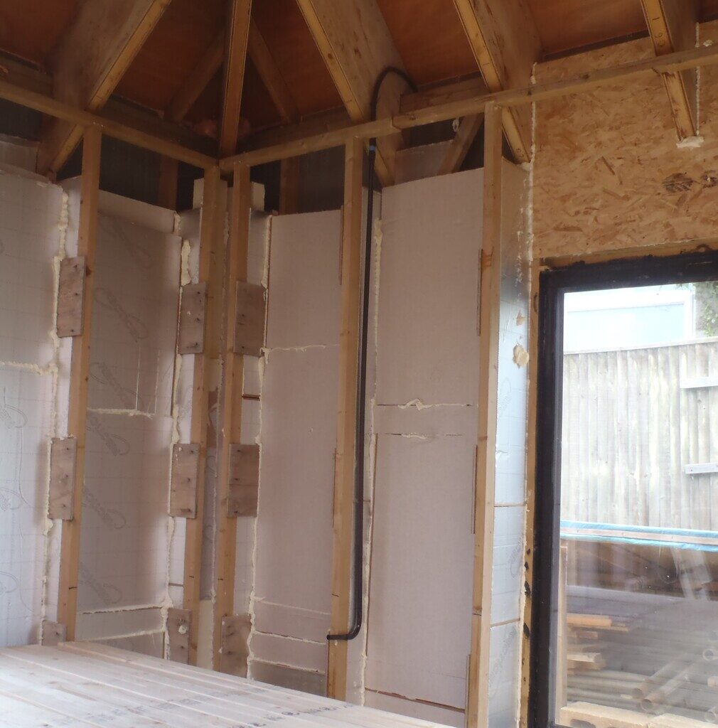
    Data-Conduit-from-eves-to-utility-rail

    Installed Dozens of Conduits and Pipes through the External Wall for Future Expansion

    Data-conduit-inside


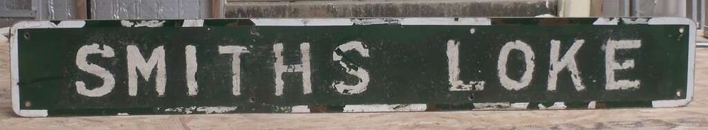
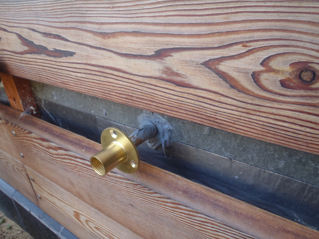
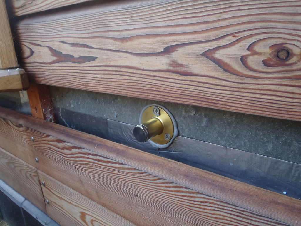
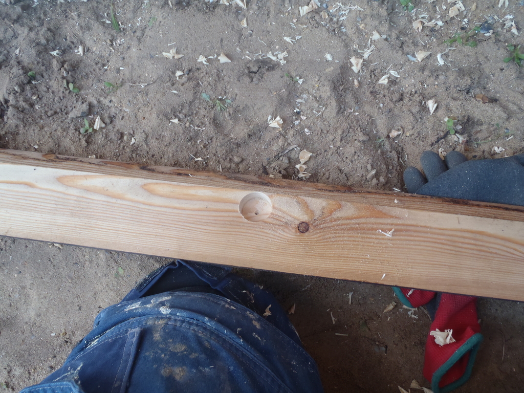
    On the second week, we got on with the job of installing the three water garden taps located on the A-B corner for the garden along the Loke, the second one over in the Patio area beside the Conservatory and the third one at the P-A corner to serve the top of the garden. We unscrewed the third from bottom Larch plank off the wall to reveal the wooden footplate sitting on the concrete wall and we drilled a 16mm hole through the wooden section and sealed the wide flange using mastic and screwed down with three stainless steel screws. Then we drilled a recess in the larch plank and refitted it.
    Installed Dozens of Conduits and Pipes through the External Wall for Future Expansion

    Tap-pipe-sealed-to-the-wall-1

    Installed Dozens of Conduits and Pipes through the External Wall for Future Expansion

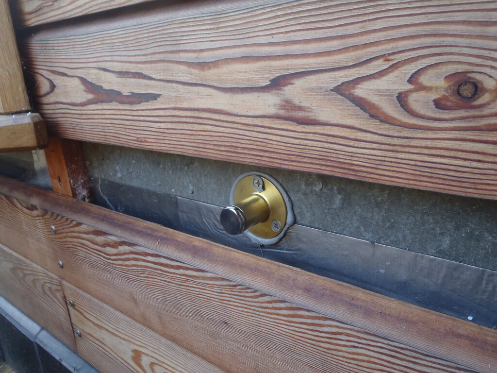
    Tap-pipe-sealed-to-the-wall-2

    Installed Dozens of Conduits and Pipes through the External Wall for Future Expansion

    Recess-in-Larch-to-cover-the-tap-pipe


    Next, was to tackle the underground connections. This meant digging a hole a foot deep and one or two “bays” wide, depending on how many connections there were. There were over a dozen of these holes and some had the similar water connection using the same copper / brass fitting, some were electrical boxes and a few were straight conduits going directly into the soil. All of them needed a hole drilling through the concrete blocks to gain access to the inside where we will eventually carry on the plumbing later on when such things will be done. These holes needed the mains powered SDS drill to cut either a 16mm or a 22mm diameter hole, either for the copper pipe or the PVC / polyethene pipe. Again, the water connection and the electrical boxes were sealed with more of the mastic and then screwed down to squeeze the thick liquid flat against the bitumen coated concrete wall.
    Installed Dozens of Conduits and Pipes through the External Wall for Future Expansion

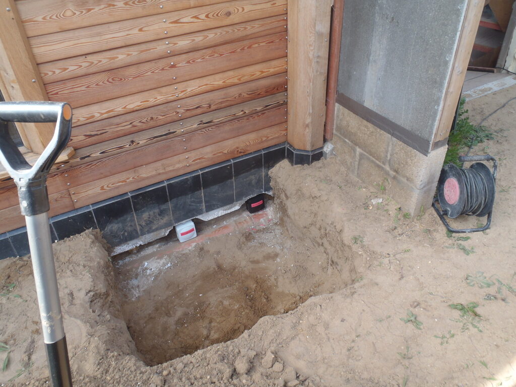
    Connections-on-P-@-Patio-1

    Installed Dozens of Conduits and Pipes through the External Wall for Future Expansion

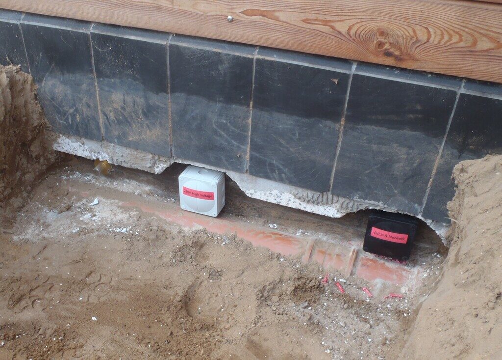
    Connections-on-P-@-Patio-2


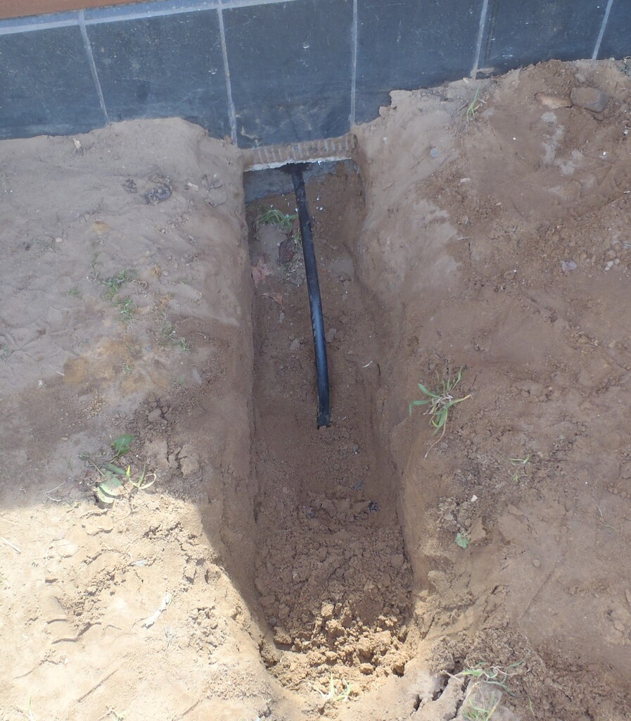
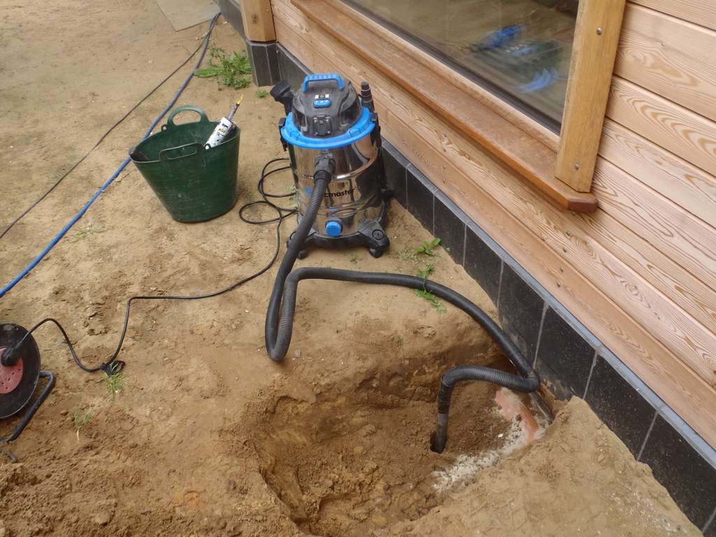
    The third type mentioned above is for the temperature probes that are monitoring our buried Energy Modules under the house and we wanted to get some idea of what the sandy soil is doing temperature wise when the Energy Modules get hot during the Summer and how the various weather conditions may affect the surrounding sandy soil around the perimeter of each module. We made a hole 2m deep using our Vacuum drill and shoved a sealed conduit down it and then through the wall.
    Installed Dozens of Conduits and Pipes through the External Wall for Future Expansion

    A-Temperature-probe-conduit-plunging-underground

    Installed Dozens of Conduits and Pipes through the External Wall for Future Expansion

    Drilling-a-deep-hole-using-a-Vacuum-cleaner


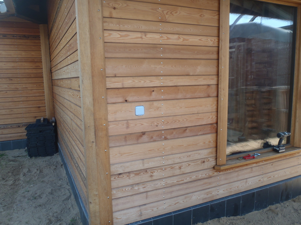
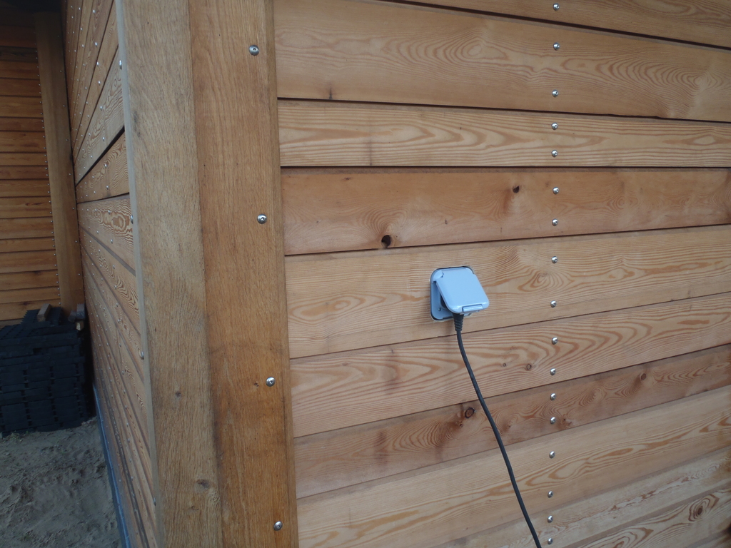
    During this week, the second week covered by this report, our electric weather proof sockets came so those were installed in three places at about 3 feet off the ground level and come out flush to the Larch cladding. We put one at the E-F (next to the Utility’s window), one will be in the M Alcove (outside Bedroom 1’s) and the final one for the Patio area next to the Conservatory. This was a straight connection through the wall, again using the rigid PVC plastic conduit, the white one to colour code as being mains voltage, just like the underground ones were too. The conduit was fitted to the back of the socket’s housing and again stuck to the cement board of the wall with more of the sticky yukky black mastic stuff with four hollow wall fixing bolts to clamp the box tight onto the wall.
    Installed Dozens of Conduits and Pipes through the External Wall for Future Expansion

    Mains-Socket-on-E-1

    Installed Dozens of Conduits and Pipes through the External Wall for Future Expansion

    Mains-Socket-on-E-2


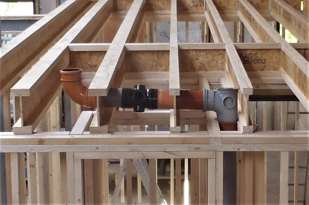
    The first couple of days of the third week was spent putting in the kitchen waste pipe underground, a 40mm diameter PVC pipework and we had to core drill rather slowly through the concrete wall. we didn’t directly connect it to the large sewage pipework already outside in the soil as there are considerations of whether we put in a garbage collection box to filter out the fibre and solid waste coming from the kitchen sink (and manually deposited on the compost heap) but there is also perhaps a simpler solution of just having a mini compost pot in the kitchen and take that pot to the compost heap now and again.

    Then we thought about what sort of letter box we wanted, we want quite large one so small parcels can be posted through it. After some discussion we made a large box which we sealed to the back of the cement board and can be finished later on.

    Installed Dozens of Conduits and Pipes through the External Wall for Future Expansion

    The-back-of-the-Letter-Box


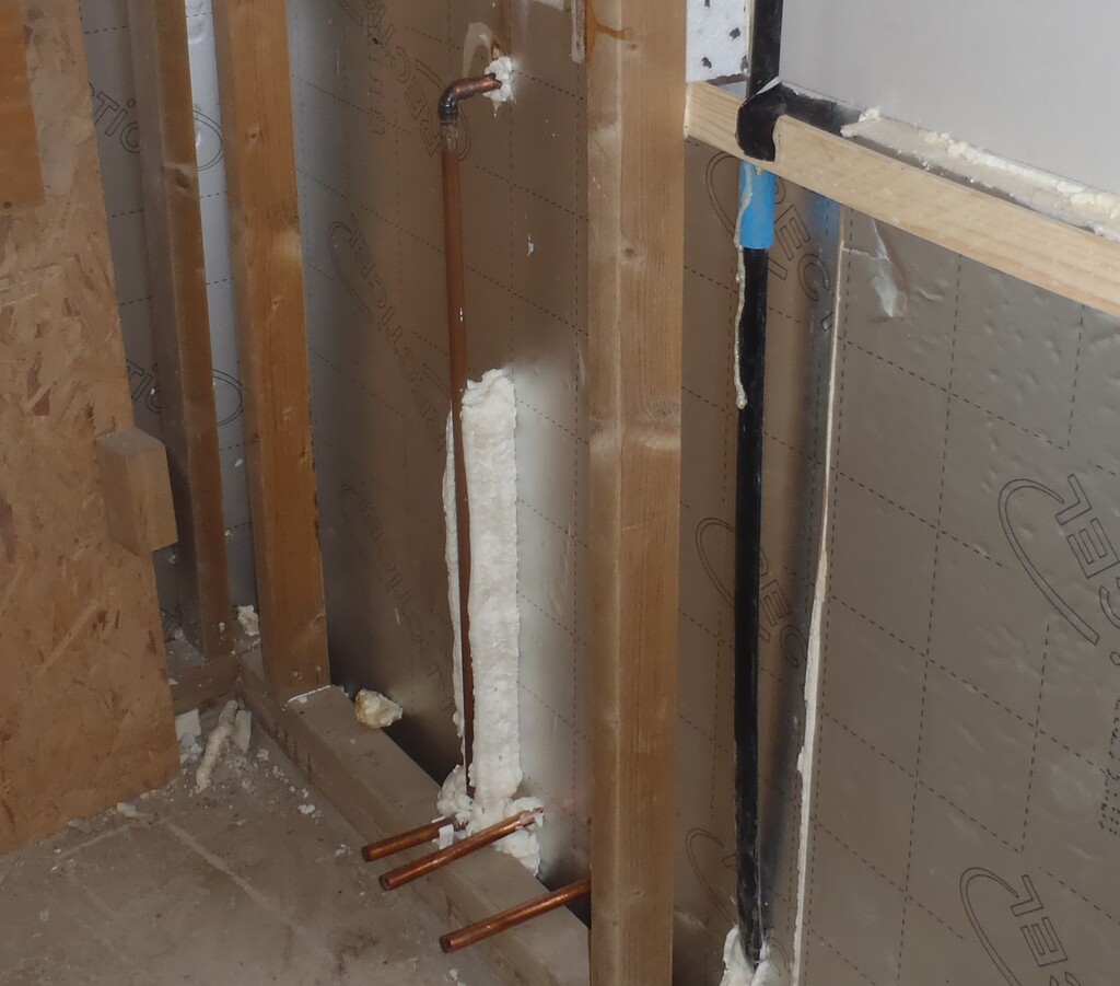
    Then, after that, we went back indoors to finished off the several conduits that came through in the middle of the wall and they needed to be diverted downwards to the floor for future onwards connections. These were the water taps and for these 15mm copper pipes, we had to put on 90degrees right angle fittings and solder them together.
    Installed Dozens of Conduits and Pipes through the External Wall for Future Expansion

    Tap-connection-down-under-floor


    And finished off bending and connecting all the electrical (of all types) conduits to the Utility Channel for easy maintenance and control of all those outside junction boxes.
    Installed Dozens of Conduits and Pipes through the External Wall for Future Expansion

    Conduits-ready-to-go-into-utility-rails


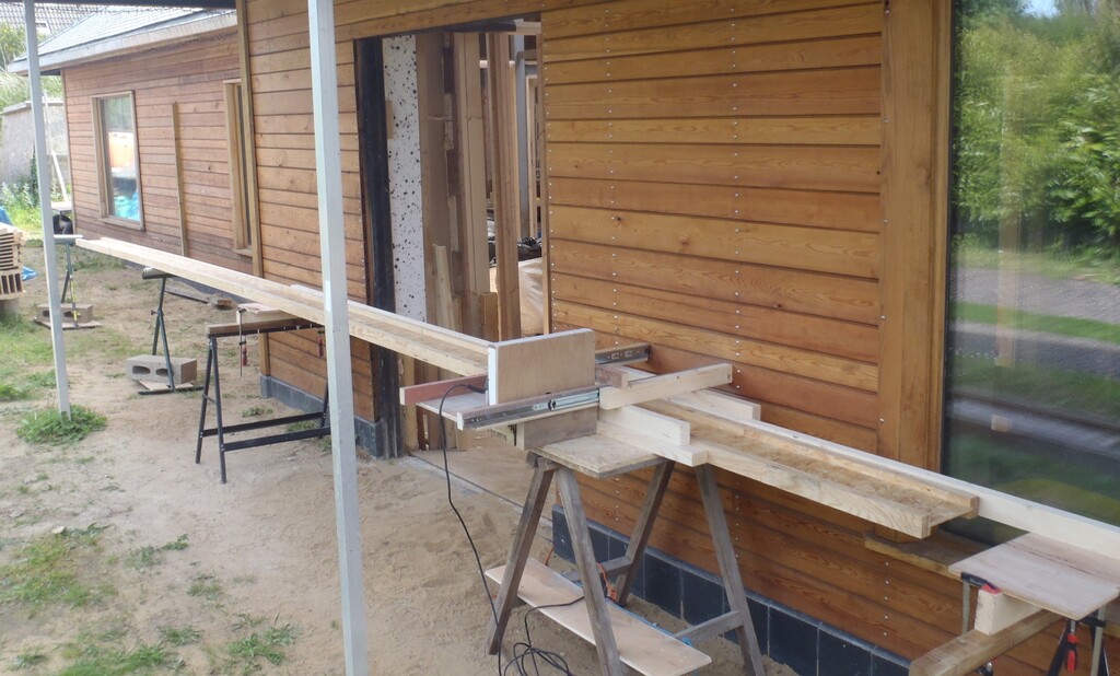
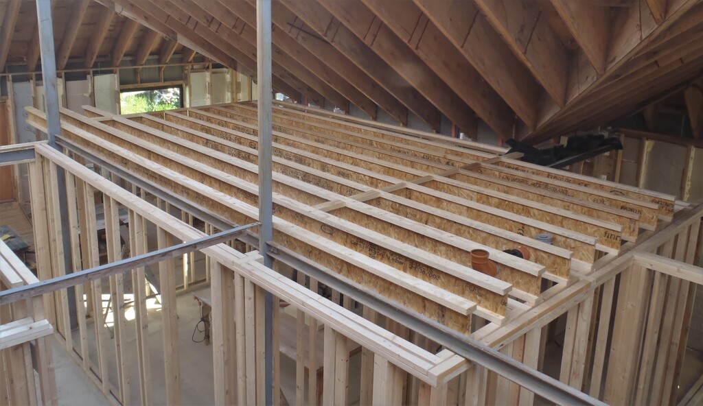
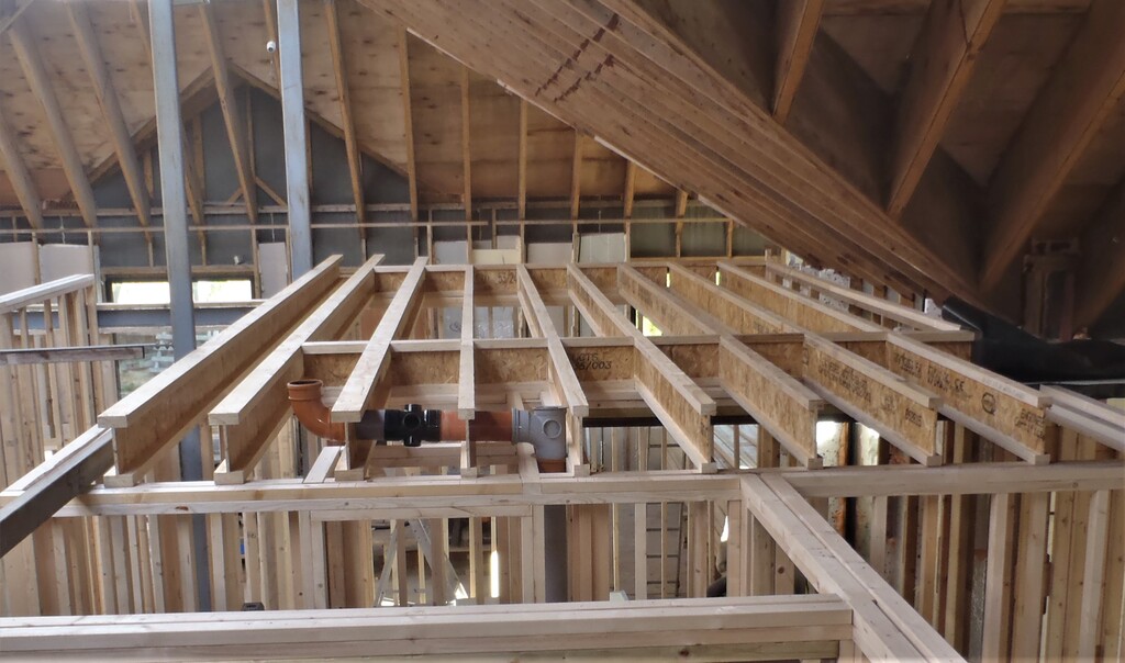
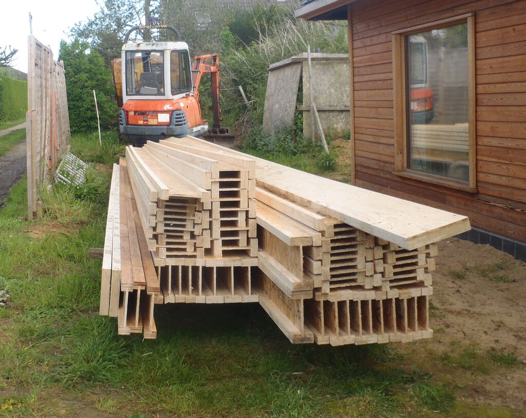
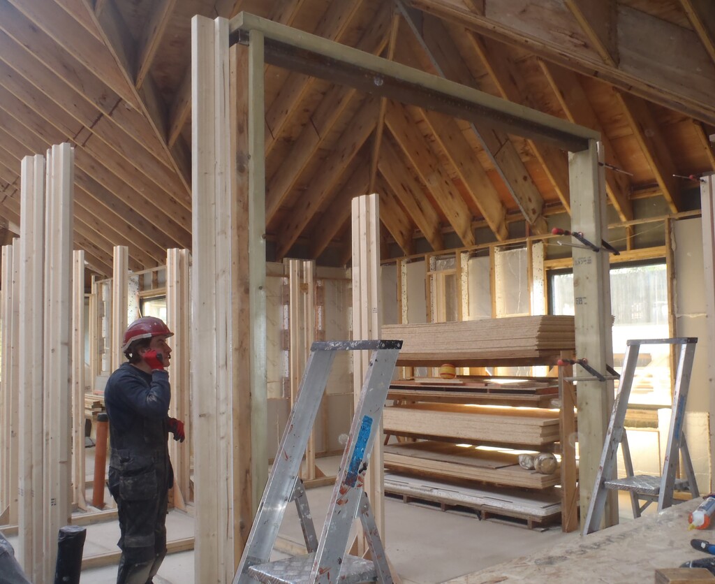
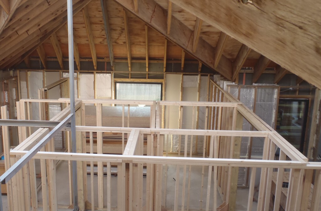
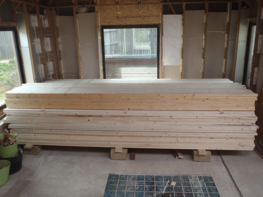
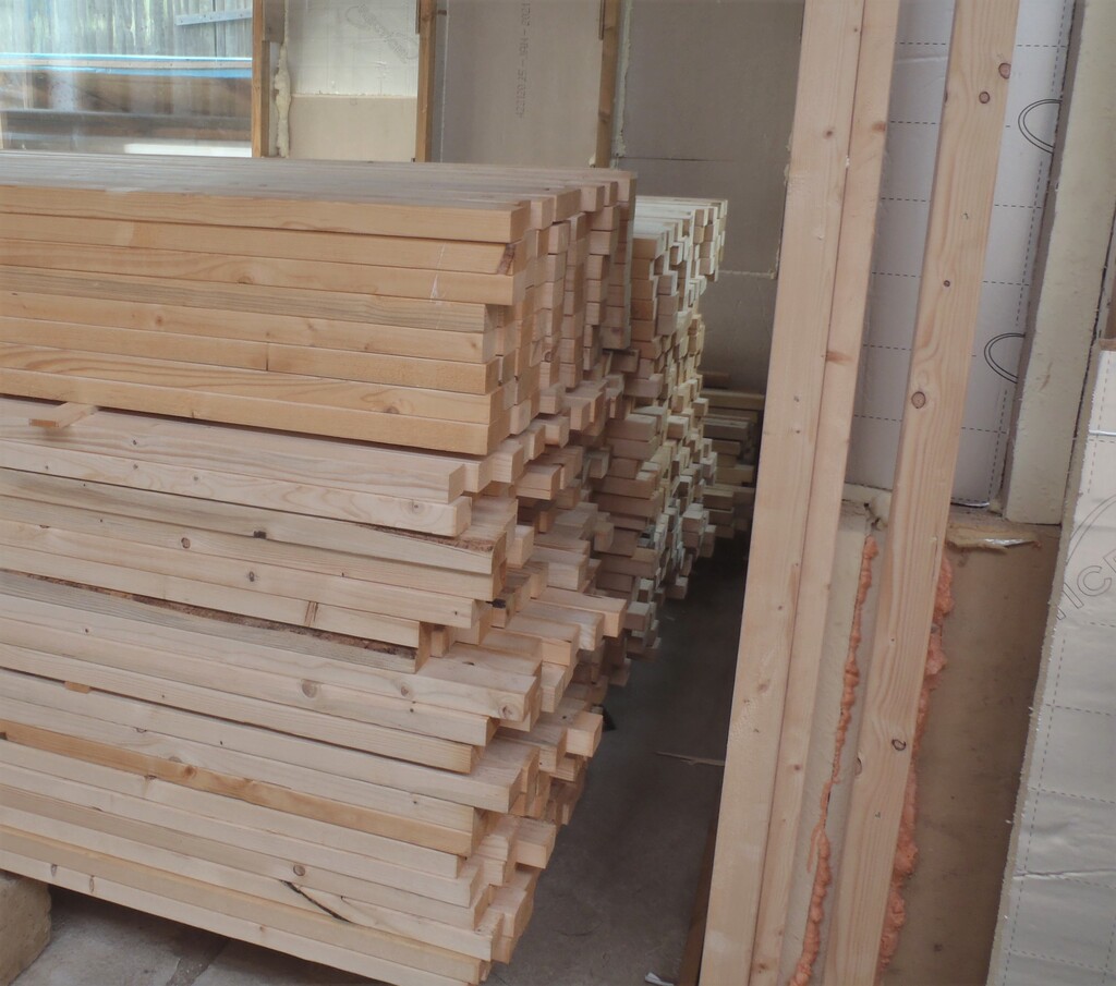
    The rest of the week was spent preparing for the arrival of the special wooden I-Beams on Monday.

  • Glass Wool for External Walls Delivered

    Our Glass Wool insulation we ordered last week has arrived today. The delivery truck parked in our local Tesco Express (after asking the staff inside the shop for permissions) and came down to confirm that we were expecting this order. There were three pallets plus two loose packets. But fortunately, he had his own diesel powered fork-lift truck onboard so all we needed to do was to bring our medium trolley to collect the two odd packets.

    So in our delivery, we received ..

    • 24 rolls of 200mm thick
    • 12 rolls of 150mm thick
    • 8 rolls of 100mm thick

    The driver placed the three pallets on our driveway and then we dismantled the pallets to move the packets (they had four rolls in a packet) into our house and parked them in our hall way where our planned stairs will be one day.

    Glass Wool for External Walls Delivered

    Delivery-of-Glasswool-for-the-walls


    This material is to be used in finish filling up the external wall cavity to both provide some extra sound absorbing effect and fire protection for our Polyurethane foam boards already in the walls. The different thicknesses were available because the amount of volume varies, with a range of 150mm to 200mm space in the upper section and 100mm gap on the lower half of the walls.

  • Ground Floor Walls Structure All Finished

    We continued the task of putting up reinforced wall posts for the hanging toilets for the cloakroom and for the en-suite of Bedroom 3 where we had to put down an additional footplate inside the knick-knack cupboard, to allow for a box to be built around the back of the toilet pipework and the sewage pipe going down into the concrete. We put another one of our homemade I-Beam element, but a shortened one.

    Then we resumed putting up a forest of posts all around the remaining Ground Floor walls including the cloakroom, linen cupboard (where we put in a double post to support an extra wooden lintel over the doorway), the en-suites and finishing off Bedroom 2 and Bedroom 1.
    Another section that had to be done was in the Great Room entrance way. This point is between the steel legs of the Skylight and it has a large C shaped steel beam (designed to hold up the first floor going over this doorway) and we needed to glue a couple of pieces of timber to the top and bottom flanges. The top one is an ordinary CLS timber plank, a 89mm wide piece but planed down from 38mm thick to 33mm thick to match up with the actual joist support level. The bottom flange however wanted to be a much wider piece, about 200mm in actual fact so we used our 18mm OSB boards and cut off two strips. We glued them together to form a 36mm thick planks and then glued this up on the bottom flange of the steel beam, all clamped overnight to dry and cure. After that, we could install the last set of posts for the ground floor, this time, the edges of the sliding door cavity
    Then the final job was to lay on the two levels of top-plate CLS timber to tie all the posts together, to tie all the walls together and create a another solid set of rooms.

    To conclude this stage of the operation of building the Ground Floor walls structure, we put on the second layer CLS timber pieces all the way around on the external walls and added a third layer across the doorway and window in our Utility Room because these have a major load from the First Floor Joists.

    We finished the week by tidying up all the pieces of cut-offs, the tools and preservative liquid, to make the place ready for the next task. That is probably be installing conduits through our external walls so we can easily feed additional cables etc. from inside to outside when we need lighting or speakers etc outside.

  • First Floor Joist I-Beams Quantified and Ordered

    After a week of calculating, analysing responses and digesting options, we have finally placed an order for a collection of Joist Beams to build our First Floor support.
    There are 61 joists and 455m in total, ranging from the shortest one of 3.2metres and all the way up to 10.8metres. These joists are a specialised hi-tech product, made entirely of natural timber materials but done in such a way that the weak points of using raw untouched wooden planks are almost completely eliminated. The joists are a wooden version of the classic steel RSJ beams (after all, RSJ stands for Rigid Structural Joist) and they have both that shape of a capital letter I, a large vertical webbing with a fitted top and bottom flanges. In the case of these wooden versions, the webbing is made of plywood or OSB to a thickness of 10mm and the flanges are a thick 36mm multiple layered plywood too. The only different is the width of these flanges, depending on how strong you want the joist to be. Of course, the other way of making stronger joist beams is to widen the webbing to spread apart the two flanges thus increasing the both the compression and tensile loads and stiffening up the whole beam. We have chosen to use one of the smaller webbing depth so that our joists are 240mm high. As part of the structural loading calculations we did several years ago as part of our submissions for planning approval, we knew that 240mm is sufficient for the job. We are using two size of flange, 96mm for the joist which extend out for the gallery and 53mm for all the rest.
    So after a round of sending quotes off to various suppliers, bouncing back questions like what happens to the waste pieces and what stock length they hold in the yard, we have settled on buying their original stock lengths of these I-Beams and cut them up ourselves. It is slightly more expensive this way because it seems that one of our suppliers makes use of all the waste pieces in other projects but in contrast, the alternative supplier (we had only 2 to choose from in the end) didn’t bother with that and always charged us for the use of the entire length of the beam and presumably threw away the waste pieces and only supply our 61 pieces at our specified lengths.
    But we had a very good idea of using these waste pieces ourselves to make noggings to help brace all the joists as required. We were going to use 18mm OSB sheets, cut up into appropriate sizes and jammed in between each joist to stop them slipping sideways and twisting. But making use of the waste I-Beam pieces, we got a much, much better and far stronger bracing the entire First Floor Joist structure together from one edge of the house to the other side.
    Hence we were quite happy to spend a further £400 to buy a total 593m of beams and getting these waste pieces ourselves and will have a far better finished structure. The final choice came and after the second supplier added on their delivery charges (which turned out to be quite a major and surprising extra cost), we selected our first supplier, placed the order, then got the money transferred over and now we wait for our delivery slot which is a long three weeks away.
    So in the meantime, we get on with different jobs like drilling holes through the exterior walls to install conduits to the outside world, putting glass wool and vapour barriers up on our walls and start putting on horizontal rails on all the walls and so on.

  • All the CLS Planks Moved Indoors and Ground Floor Walls Is Going Up

    We have resumed our task of building up the Ground Floor’s walls, at least, the structural framework structure using our 63mm CLS timber planks and over the last eight days we got quite a long way forward. But one of the first jobs was to redo the vertical timber pieces that were glued to five of our steel legs, we discovered that we didn’t do a very good job in the first place, or rather we hadn’t realised that the primer paint was not very well stuck down as the metal wasn’t very clean when it got painted years ago. So we easily ripped off the timber pieces and then used the angle grinder with a metal scrubbing disc to polish the metal to a nice shiny finish. We also cleaned the timber planks as well using a clean but similar sanding disc and finally applied a fresh coat of PU glue and reattached the timber back to the steel legs.

    The next task was to look at the four wet rooms, the bathroom and the three en-suites, because we wanted to put across the entrance ways, a proper and robust lintel to support the first floor joist without having to need any supporting posts underneath. This feature would then allow us to have the option of having complete glass walls and door for our en-suite or indeed other designs we may come across. We had four left-over pieces of rectangular tubing from our steel legs which hold up the Skylight which proved to just be long enough to bridge over the entrances. These steel legs are 100mm by 50mm with 5mm thick walls so they turned out to be very useful to serve as very strong lintels. We only had to slice very small bits off two of them to make them fit for the Bathroom and bedroom 3’s en-suite. Next, to sort out the pile of 145mm by 45mm timber planks and decide on which ones we can used. We decided that we needed one of these wide planks to help with the lintel and combined with the steel element, will help secure the joists in place and properly transfer the load of the first floor sideways to the posts. These posts are made up of another piece of the 145mm wide timber, coupled with narrower 95mm by 45mm plank we had left over and was sitting in our swimming lane storage yard. So each composite lintel was made from gluing together the steel element with the 145mm wide wooden piece.

    All the CLS Planks Moved Indoors and Ground Floor Walls Is Going Up

    Sliding-door-lintels-started


    And then we glued the two wooden pieces, the 145mm and the 95mm planks together to form the integrated post, including a notch cut out to receive the steel part of the lintel. We left that to dry and cure. So in the meantime, we spent a few hours bringing in the first load of CLS timber planks that we have lying outside that was delivered a few weeks ago. We moved about 150 planks.

    The following day saw the new lintels and their posts get fitted and fixed into place, making sure that each one was straight and vertical.

    All the CLS Planks Moved Indoors and Ground Floor Walls Is Going Up

    End-of-an-En-Suite-lintel

    All the CLS Planks Moved Indoors and Ground Floor Walls Is Going Up

    Steel-lintel-for-Daphnes-En-Suite


    After that, we could carry on in building the stud walls from all the footplates we had put down a month or so ago. We started over in Bedroom 3, making sure that the load bearing elements had studs spaced apart by 400mm and the perpendicular walls had 600mm spaced legs. We went around all the smaller rooms, the the Bathroom, en-suite 3, the Tech and Knickknack cupboards plus one wall (the long wall) of Bedroom 2 and then the corridors including doing two doorways. Finally, we put on the two layers of the top plates, overlapping in each direction to help bind all the section of walls together.
    All the CLS Planks Moved Indoors and Ground Floor Walls Is Going Up

    First-few-rooms-are-Framed


    One of the tasks we wanted to do since we were getting on much quicker than we imagined in building these walls, is to find and buy the I-beam joists we would need for building the first floor so we spent one of the mornings measuring all the lengths of various rooms, to make sure that what is actually the real world measurements, matches the technical drawings, before we send off the final shopping list of these composite wooden I-beams. We need 61 in total, about 460metres in all, ranging from 5metres to double that size of nearly 11metres. It was quite good and matched within 20 to 30mm to the drawing but we had always intended to round up the measurements before sending the list off to four local suppliers and one manufacturer. But only two suppliers have replied with quotes in the ball park figure of £2,800+VAT in total, about £6 per metre. This price includes the wastage from cutting the beams from stock lengths and we realised that we could make use of these waste pieces, by slicing them up into shorter lengths and turn into our noggings to strengthen the sideways anchorage of our very long and tall joist hence utilising all the wastage that we would had paid for anyway.
    Then, spread over the afternoon of Friday and the next morning, we finished moving in the rest of the CLS 63mm planks to our indoor storage area. This makes a total of 600 planks we moved this week.
    Added with our existing pile, we now have 772 planks to be used for building the ground floor walls including the horizontal structs, the floor support framework, the first floor walls and ceiling. We hope we got enough!
    All the CLS Planks Moved Indoors and Ground Floor Walls Is Going Up

    CLS-All-moved-in

    All the CLS Planks Moved Indoors and Ground Floor Walls Is Going Up

    More-than-750-pieces-of-CLS


    For the rest of Saturday, we marked out roughly where all the wall stud posts will go, including making provision for the three hanging toilets, the various doorways like the sliding doors for the cloakroom. There is a total of 86 of these posts to do, to finish off the ground floor walls, of which 25 have their ends dipped into timber preservative to ensure long term survival in these various wet rooms.
    For the hanging toilets, we designed our own I-beams structure, a pair of CLS timber with four pieces of plywood glued and screwed across to make a ladder like combined element. This will help stiffen up the point where the toilets will be mounted and keep everything nice and stable. So between Bedroom 2 and 3 pair of en-suites, we positioned the three of these I-beam elements so each en-suite can have their toilet and connect into the same pipework.
    All the CLS Planks Moved Indoors and Ground Floor Walls Is Going Up

    First-toilet-wall-framed


    They are positioned so that we meet the minimal legal requirement of at least 500mm spacing on each side of the toilet including the bowl itself.
    Next week, we can do the cloakroom in a similar manner and also do the same thing for Bedroom 3?s en-suite too. Then we will carry on putting up the rest of the stud posts.