We have been spending a day here, a day there, whenever we were waiting for glue to set, paint to dry etc. etc. and got on with the task of designing and building a heat exchanger coils for our Hot Water tank sitting in our Utility Cupboard. We wanted to have a system where we could run in various hot water, or indeed cooler water sometimes, to transfer energy into, or out of, the tank. We are going to use lots of copper pipes, narrow 10mm wide copper pipes, and bend it into a coil, to form a tall rectangular spread out maze of pipe bending this way and that way, to form a column. We want to make four of these, so that they stand in a line, inside our Hot Water tank. They will be connected to a 22mm copper pipe and a tiny little manifold which will allow four 10mm pipes to join into the 22mm pipe. The 22mm would then go up to the top of the tank and exit to the outside world.
So we were thinking of doing a series of “figure-of-eight” loops, wrapping the copper pipe around two 110mm waste pipes, set apart very slightly, making sure the overall dimensions kept within 150mm by 300mm. In fact, we made sure that the longer length didn’t exceed 270mm so that there was room to slide the finished article into our tank. We found some left-over waste pipe, made two equal length, measuring 250mm and then cut little slots at one end, all the way around, to form little bendable tabs. We heated up the plastic to bend these tabs out and then we screwed the two pipes onto a block of wood.
We then started trying to bend the copper pipe around these template, but discovered straight away that the thin walled copper pipe kept on buckling and didn’t want to bend smoothly around. Oh Dear!
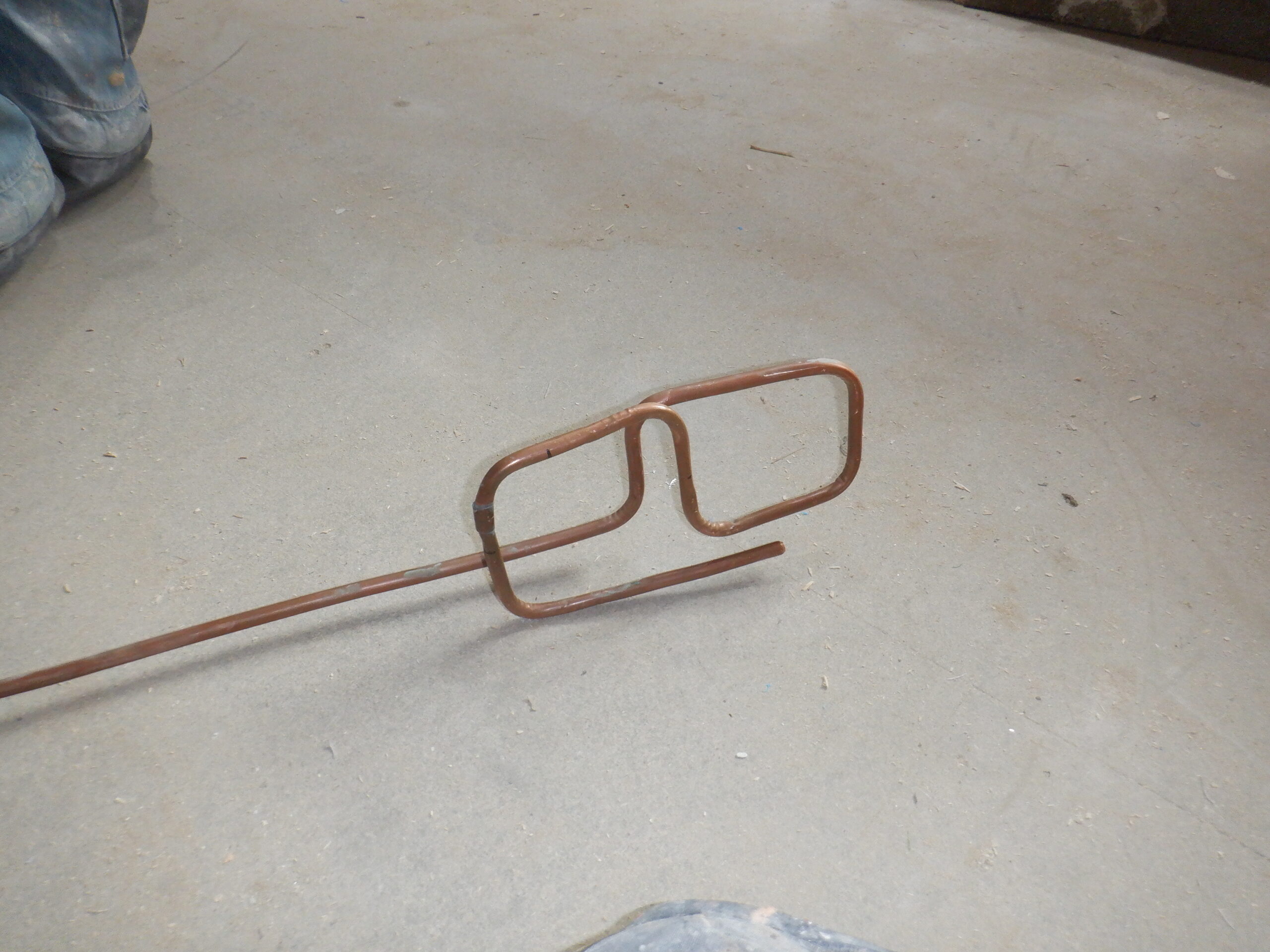
So for Plan B! We decided to use our miniature pipe bender tool, designed to cleanly bend these microbore pipes but at a much tighter radius, of around 20mm, forming a bend that would be only 40mm across for a full circle. We still tried to use our existing template, to bend the copper pipe with right angle corners, and 60degree in the middle when we wanted to make the “figure-of-eight” shape but it was proofing very difficult. It was a matter of getting precise distances from one bend to the start of the next bend, to apply the bending tool in that precise location, to end up having the copper pipe going around the two upright plastic waste pipes. We had a little chaotic set of coils.

Trying out pipe bending
By the way, we were using old copper pipe we had from a previous project some 15 years ago, so we were not losing material here with our experiments!!
What we ended up, as you can see in the photo above, is a random collection of lengths and gaps, which gave us the idea that if we change our approach slightly, like for example, if we build a rectangular box and, instead of the two plastic tubes, we mounted two wooden pillars using 63mm CLS timber, to ensure that we had maintained a cleared section to allow the insertion of the immersed electrical heaters as well. This box measures 270mm long by 130mm wide.
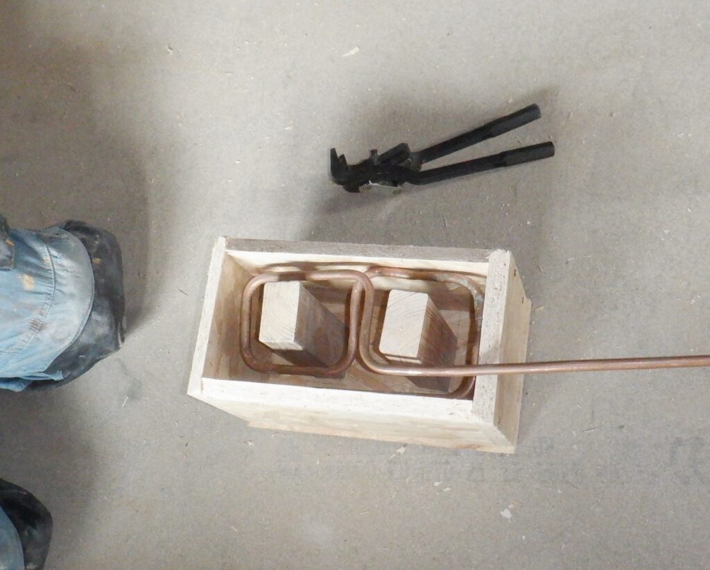
Frame to constrain tube bending
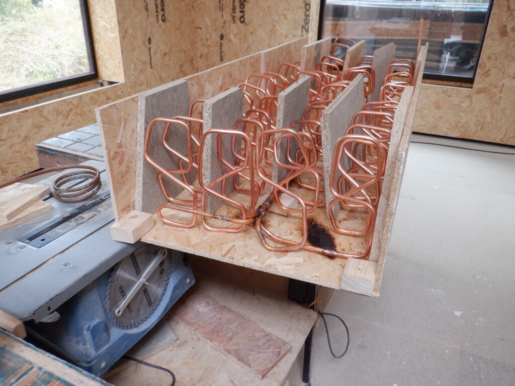
We did another test run and it was much easier to randomly bend the copper pipe at various points, so long as it obeyed the basic requirement of going around each pillar in a figure of 8 movement, it doesn’t matter where or what path the copper pipe takes. It looks quite reasonable.
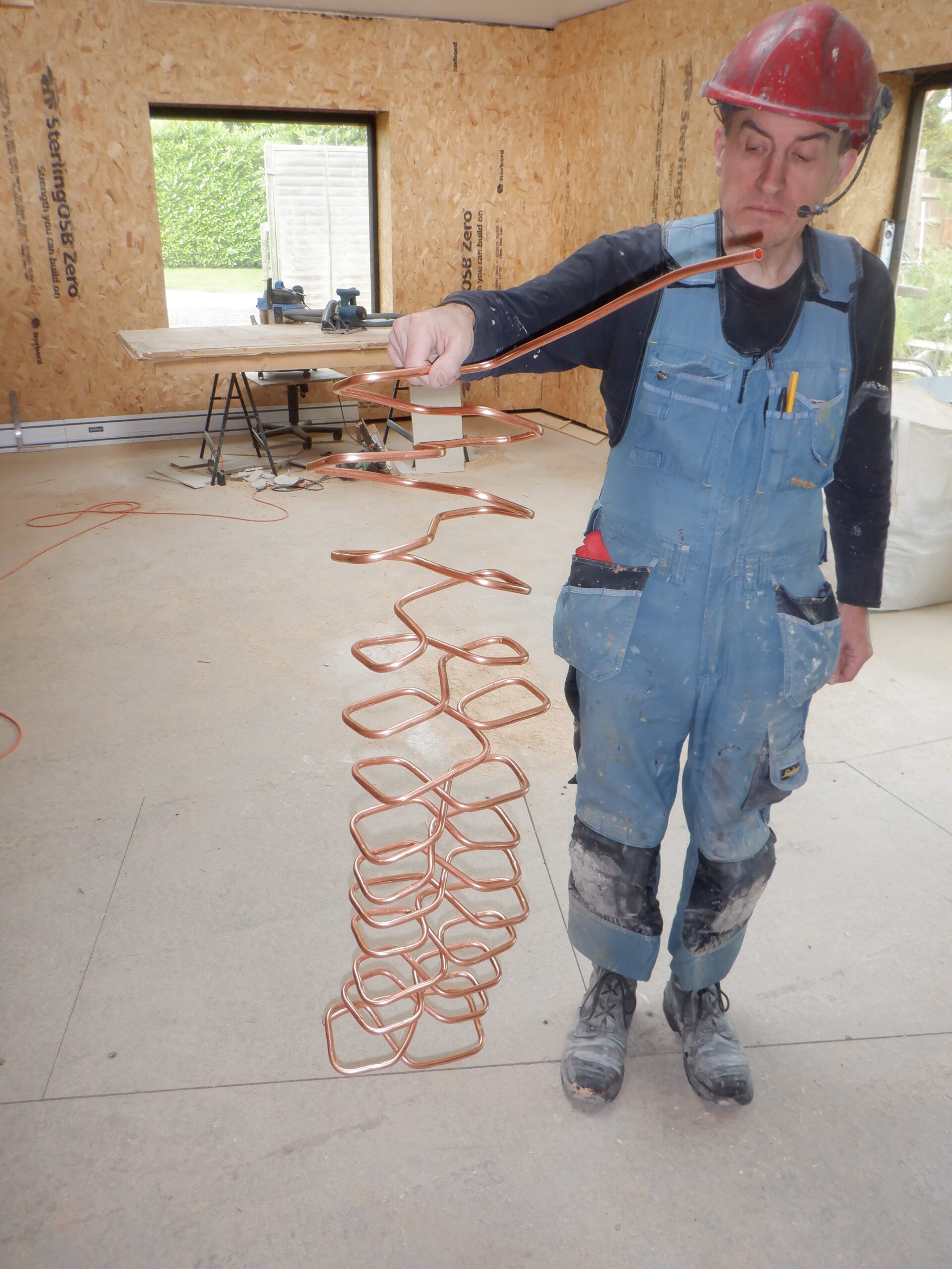
So, we committed ourselves to using our freshly bought boxes of 10mm copper pipes, and proceeded to bend one column of random lengths and angles, to bend the entire 10 metres of the copper pipe, all into that limiting rectangular requirements. It took a couple of hours to do the job, but we ended up with a column, vaguely rectangular in shape. We pulled the approximately thirteen loops out, stretching it out to about 1metre tall.

First heat exhanger formed
On another day, while waiting for the Cloakroom paint to dry, made two more “coils”, this time only taking about an hour to do all the bends. The third one had a slight crumpling up of one of the bends so we had to chop that out and replace it with a new bend and soldered the replacement back into that location.
Then we did the fourth and final one the other day. We now have four of them, ready to be assembled together later on.
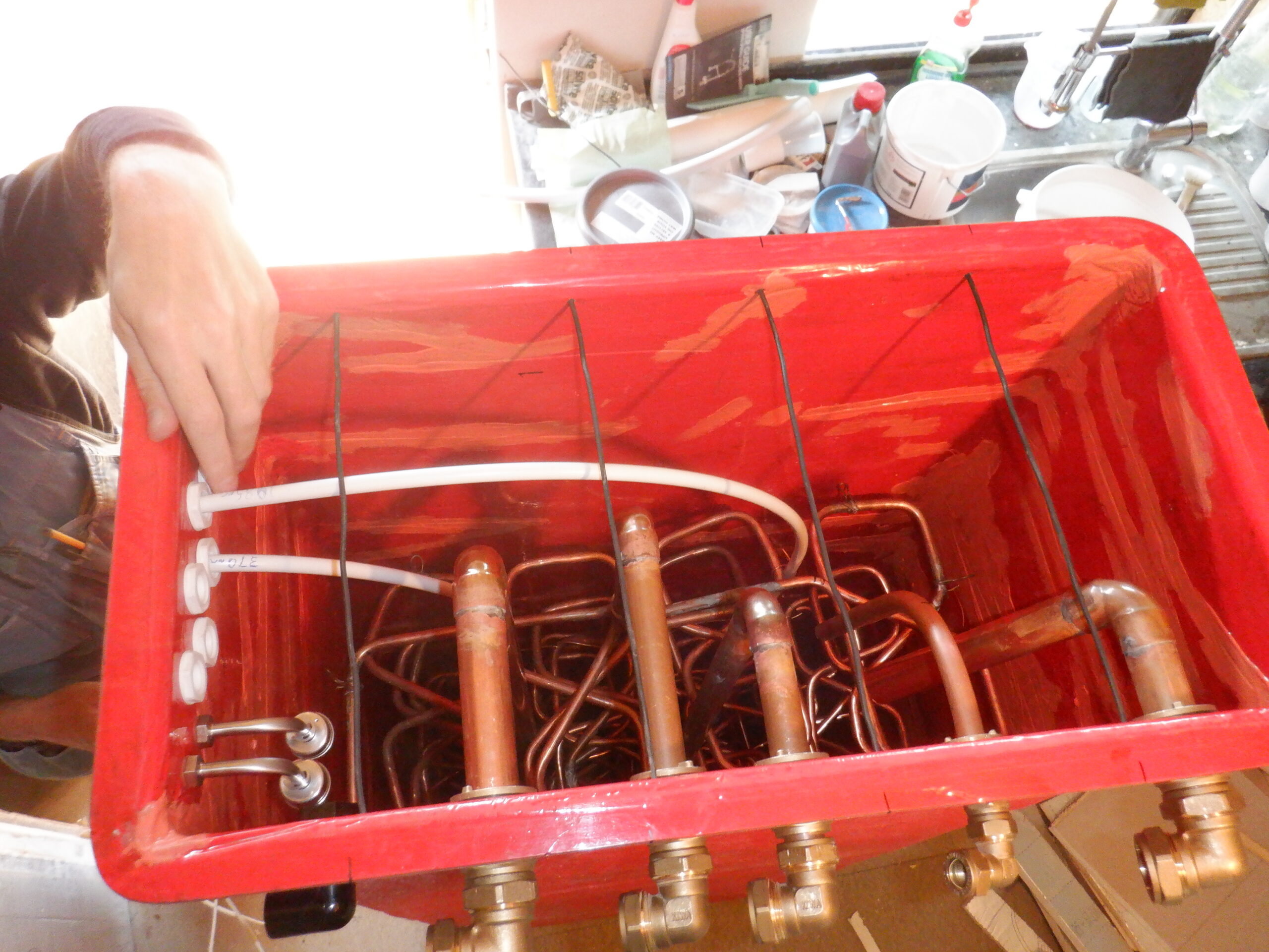
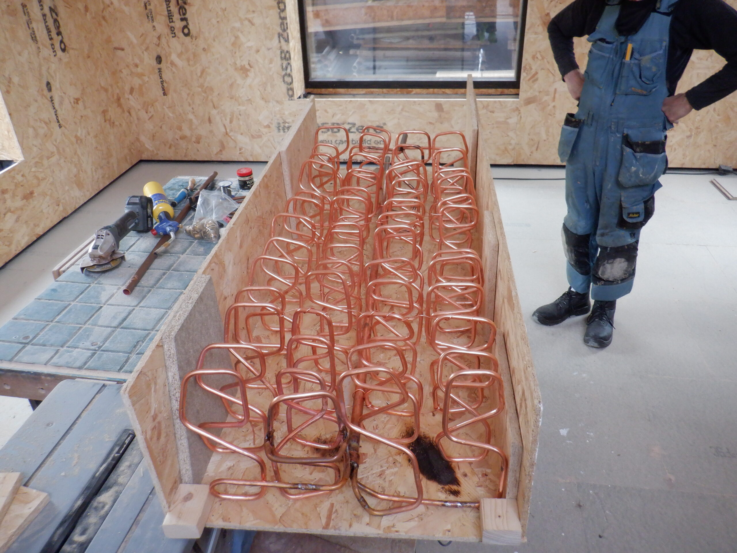
On another occasion, while we were waiting for a new tin of acrylic varnish to arrive, we got on with the job of assembling our four coils, to form a single module, ready to be slid into the Hot Water Tank. So, towards this aim, we put together a rough and ready simple template of our hot tank, just the back and two sides, measuring 600mm wide and 300mm high, and 1700mm long, emulating the shape and size of our tank. Then, we put in 100mm wooden blocks at the top, to make sure that the copper coils do not occupy too far up the tank and we did a similar thing at the bottom, but this time, only a 50mm blocks so we can guarantee a buffer of water underneath the coils.
We then stretched out all four coils, to fill the majority of the space. We noted that we could, and did, slide in pieces of 18mm and 22mm thick boards in between the coils, including on the outside too and that helped keep them much neater and separated from each other.
Now these four separate coils needs to be connected together. I mean the actual copper pipes at each end, so that the water coming in, and out, of the tank, via a 22mm copper pipe, can be split up and flowing around the four group of coils, transferring the energy in one direction or another.
We got a very neat brass adapter that fits to a 22mm size copper pipe and four 10mm holes, arranged in a two by two grid, on the other side. We managed to carefully bend each separate coil “tails”, sometimes with an extension piece, and connect each tail into this adapter. Then, we cleaned all the joints, put on flux and then got our gas torch to heat up all the joints and melt solder in the joints.
Heat Exchangers Base
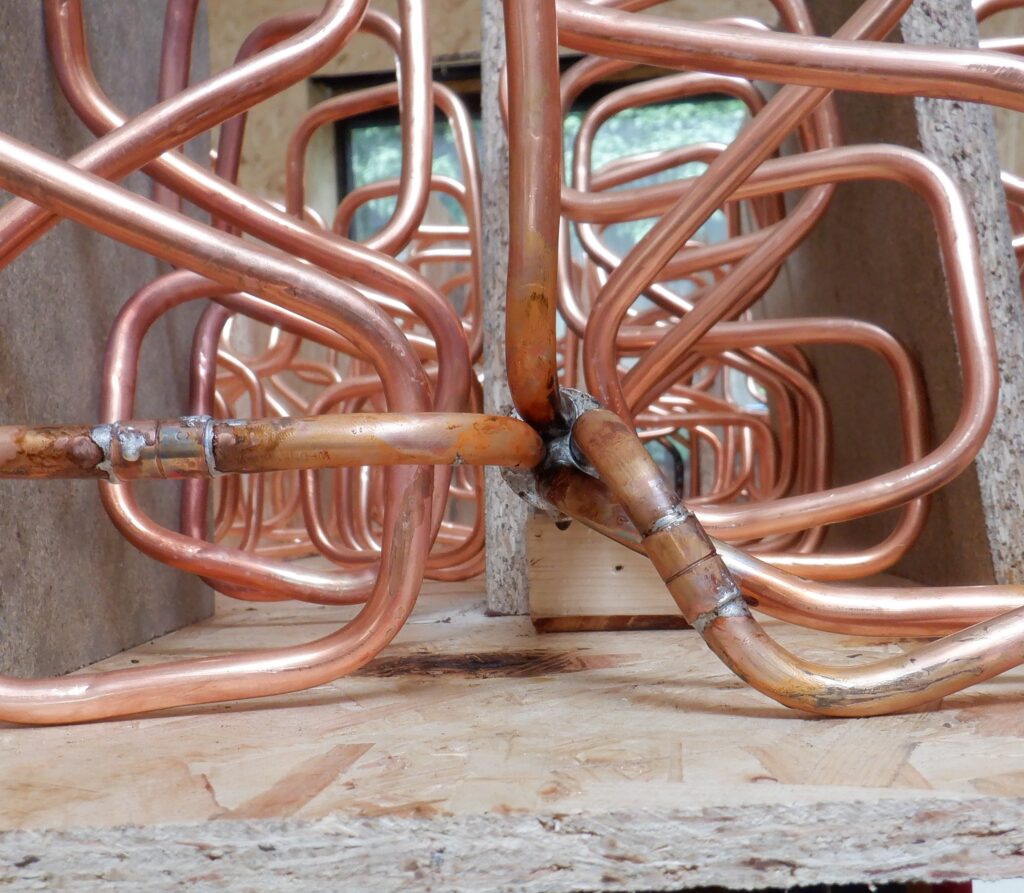
Heat Exchangers base manifold
The 22mm copper pipe went up the middle and pokes out the top end.
We then repeated the process to the other end of the coils, and soldered the adapter and joints in a similar manner. This time, we put on a little short piece of the 22mm pipe. Both of these pipes will have elbow right angle bends but we will do that later on when we got the whole thing inserted into our tank.
We then bend a small piece of 10mm pipe, into a “U”, to make a “foot” to take the weight of the heat exchanger and also maintain a 50mm gap at the bottom of the tank. That was also soldered into place too.
Then we slid in a length of 28mm copper pipe down through the coils and anchored that into place by twisting some thick copper wire we found in our left-over cable scrap box. We also threaded some more of the thick electrical wire (we stripped off the plastic coating) and anchored the coils together as well, to stop it wiggling around.

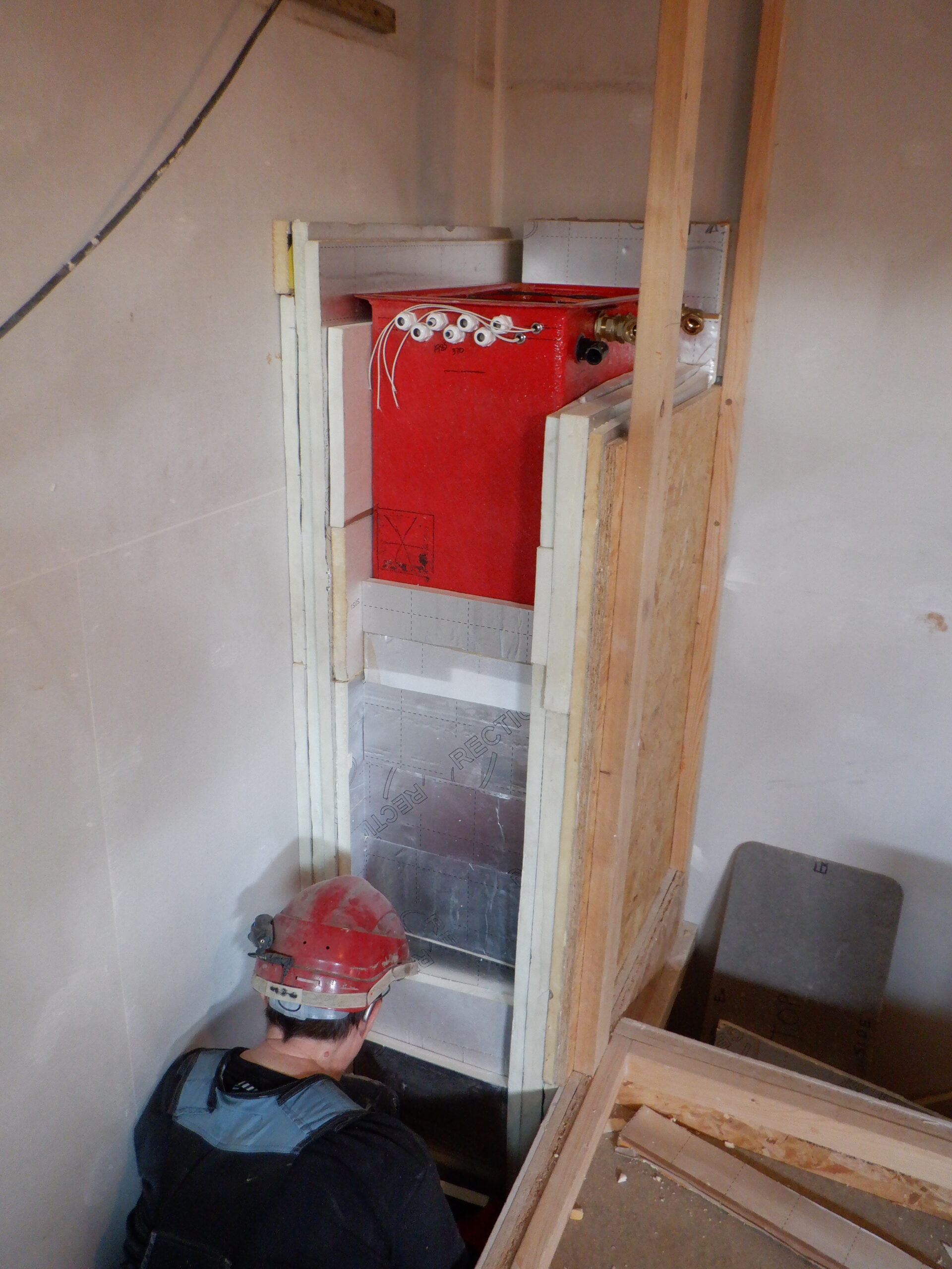
Heat Exchangers in place
Another additional little task we did, was to twist little pieces of wire on the outside of the coils, between it and the walls of the tank, to provide a simple way to make sure that the coily module will sit nice and centred in the tank and keep away from the wall surfaces. We had to solder these pieces into place, to stop them twisting out of alignment.
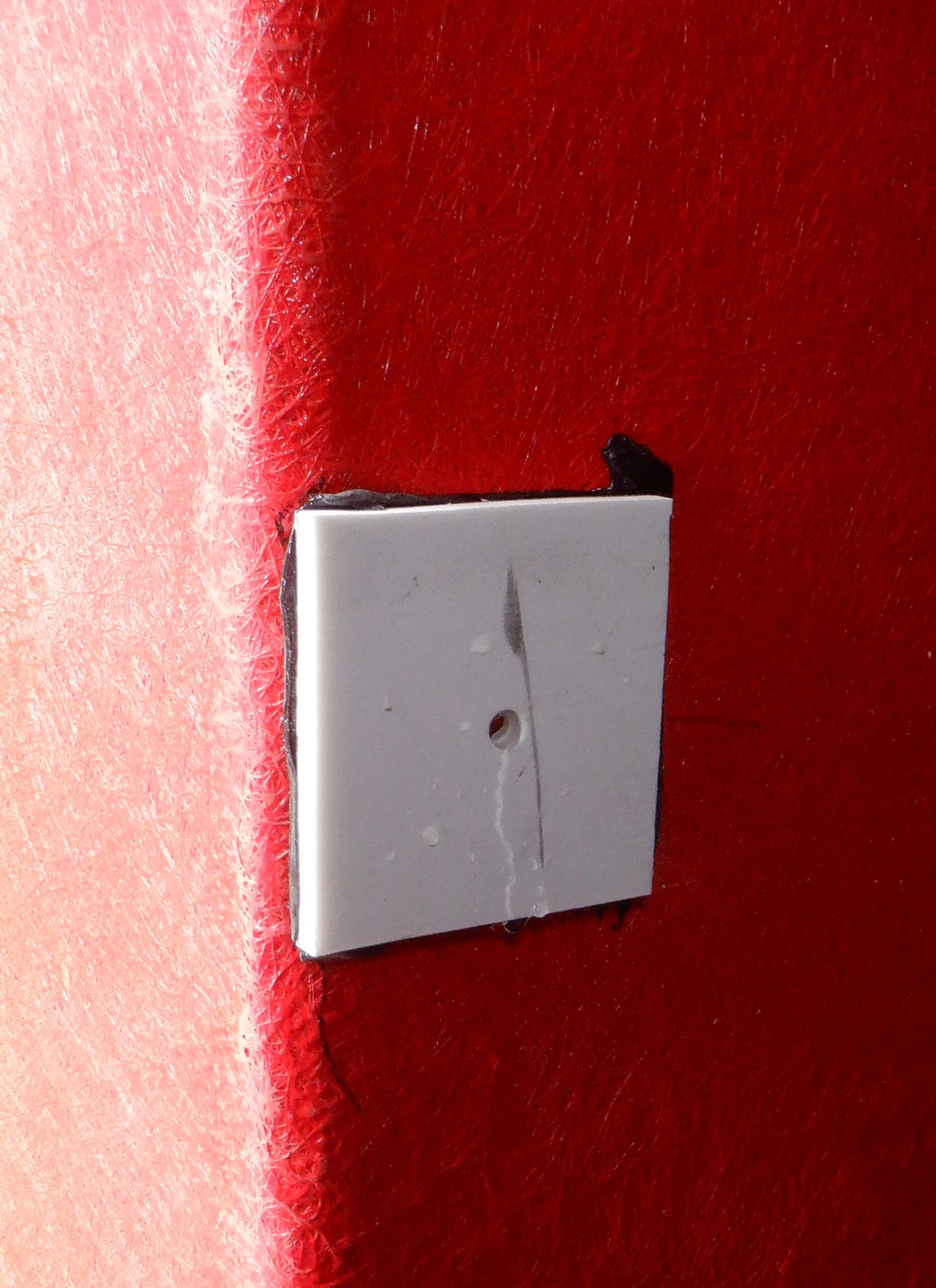
All these pipes (the two 22mm ones plus also two 28mm ones) and also a 15mm filling pipe that we haven’t mentioned yet, will all need a tank connector mounted at the top of the tank, to allow the copper pipe to gain access to the outside world. But, we want to slide the copper pipe right through these connectors, but that can’t happen until we have grinded an internal flange away. We used a 16mm HSS drill to ream out the 15mm tank connector, and used a tungsten carbide grinder to do the job in the four larger connectors.
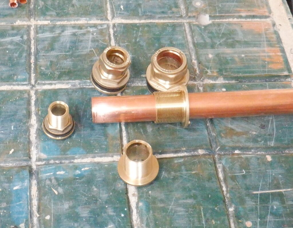
Tank Connectors reamed out
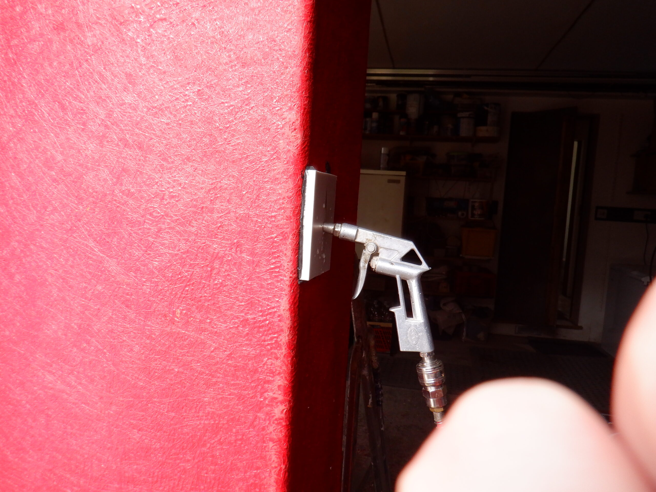
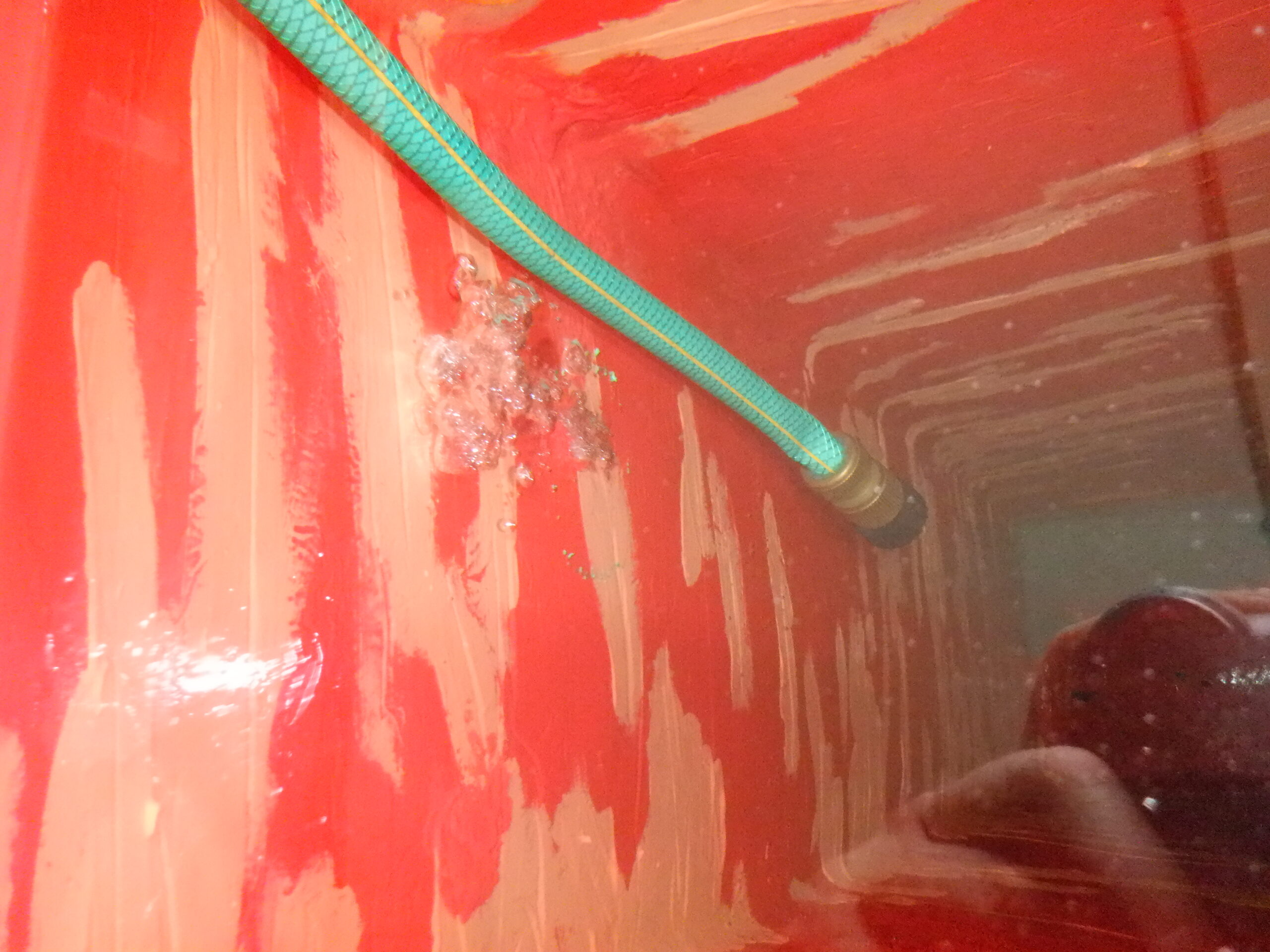
finally, we could do a “leak” test at last! We connected up our compressed air adapter which we had previously assembled, using various plumbing bits and pieces, joined to our tyre adaptor. We push it on the 22mm pipe, blasted air down inside the long coily pipes, to remove any rubbish. Then, we put on an end stop on the other 22mm pipe and built up the air pressure inside the pipe. We had a hissing sound!! We squirted some soapy water on everything, to track down the source of the hissing noise and eventually located it to a repaired section where one of the inline joints was leaking. It took us two goes to plug the gap in the joint with melted solder. We then tested everything again and this time, we held tight! Our testing adaptor has a digital pressure gauge and we put in 3.90bars of air and it stayed steady for a couple of hours, only very slightly dropping to 3.88bars, which is probably as a result of temperature change. We had squirted more soapy water on all the joints and see if bubbles formed like a little miniature volcano .. but none developed. Yippee!
The last thing we did, was to slide a length of plastic 10mm pipe down in among the coils, to serve as an temperature probe. We sealed the bottom end with a brass end cap compression fitting, to make it water proof, but also, to provide a good metal heat sink to help warm up the thermometer sensor that we will slide down inside the 10mm plastic pipe. We even put in a blob of thermal transfer paste, to help improve the connection between the thermometer sensor and the hot water that it will be measuring near the bottom of the tank. We did another one, but a much shorter one, to measure the top of the tank.
That concludes making the Heat Exchanger module !!
The next job is to patch up the tank itself and then we can install the heat exchanger in for real, and connect all the pipes through those tank connectors to the outside world!!