The modules for the Garden Room’s Utility rail had their third and final coat of paint, the full gloss mid-grey coat!
Tomorrow they will be mounted into the Utility Rail itself and have the sockets and switches fixed on.
The Garage
The modules for the Garden Room’s Utility rail had their third and final coat of paint, the full gloss mid-grey coat!
Tomorrow they will be mounted into the Utility Rail itself and have the sockets and switches fixed on.
Today we started building the kitchen cabinets and draws and worktops. We sliced up 4 sheets of 18mm OSB into cabinets to hold the ovens and microwave cooker plus two stacks of draws. The two stacks of similar set of draws are as follows: two 100mm, one 150mm and one 300mm high draws, all 600mm wide and 550mm deep. The worktop will sit on top next to the right of the oven stack and the worktop will have a rectangular section removed for the induction hob. The whole thing will be built up from a base board which in turn will be on adjustable feet with a plinth placed in front!
The modules have been painted their second coat of paint, this time an undercoat of a mid-grey.
Tomorrow the final full gloss coat will go on!
The 35 modules for the Garden Room’s Utility Rail has been painted with primer but 20 of them also has been holed! Some had a single socket (or switch) cut-out and some had the double socket cut-outs!
Next is to mix some white and black oil paint to make a mid-grey colour and apply the first coat.
We have trimmed and sliced edges on all the Utility Rail modules and arranged them around the Garden Room.
The basic size of an module is 610mm long and 150mm high. They overlap the painted wall surface by 5mm top and bottom to allow the future possibility for different wall coverings like paper.
Next we will cut out holes for sockets and switches in certain places around the room, to serve different devices.
And then paint them.
The header tank and the pipes, on the roof, are now fully insulated and wrapped up to protect them both from rain and frost.
The header tank has the capacity for 500litres of water, supplied either from the mains water or our rain water tank. The rain water can be controlled via the computer so if it is required that we cannot use the rain water for the garden room then we can switch it off and rely only on the mains water.
As part of the temporary nature in using the garden room as our kitchen, we have laid in mains cables for the cooker hob and the ovens, and the immersion heater. The ring mains is also laid in. all it needs is to have the sockets and switches installed in the utility rail etc.
Five cables (two 4mm2 and three 2.5mm2) were routed from the Consumer Unit, along the utility rail to the garden room. Then one 2.5mm2 cable was placed in the utility rail, all the way around the Garden Room itself.
The next task is to wire up all the sockets and switches which will be mounted in modules and fitted in the Utility Rail. This will be done later.
The rain tank had a submerged pump lowered down into the water and connected to the pipe that goes up to the header tank. It was tested and a gush of water duly occurred!
The total head difference between the level in the underground rain tank and the level of the input pipe in the header tank up on the roof is about 5metres (16feet) and the flow rate was quite respectable.
Also a level detector was designed and built using 7 little float switches separated by 150mm (6inches). This will go down into the rain tank so we can keep an eye on the level of the water, recording how much rain we have collected and knowing when the tank is empty so that the pump doesn’t run dry.
There is a similar level detector on the header tank as well but this time there is only 2 float switches, set 100mm (4inches) apart so we can control when to start filling the header tank up using the water from the rain tank and when to stop filling!!
In situations where we have run out of rain water then the old fashioned cistern ball valve will keep the header tank topped up with mains water, but at a reduced level.
We have been putting insulation panels in and around the tank and the pipes to protect them from frost. We used 50mm (2inches) of PU foam so it should survive the Winter months.
The last job to do on the header tank is to wrap the final structure in rain proof material.
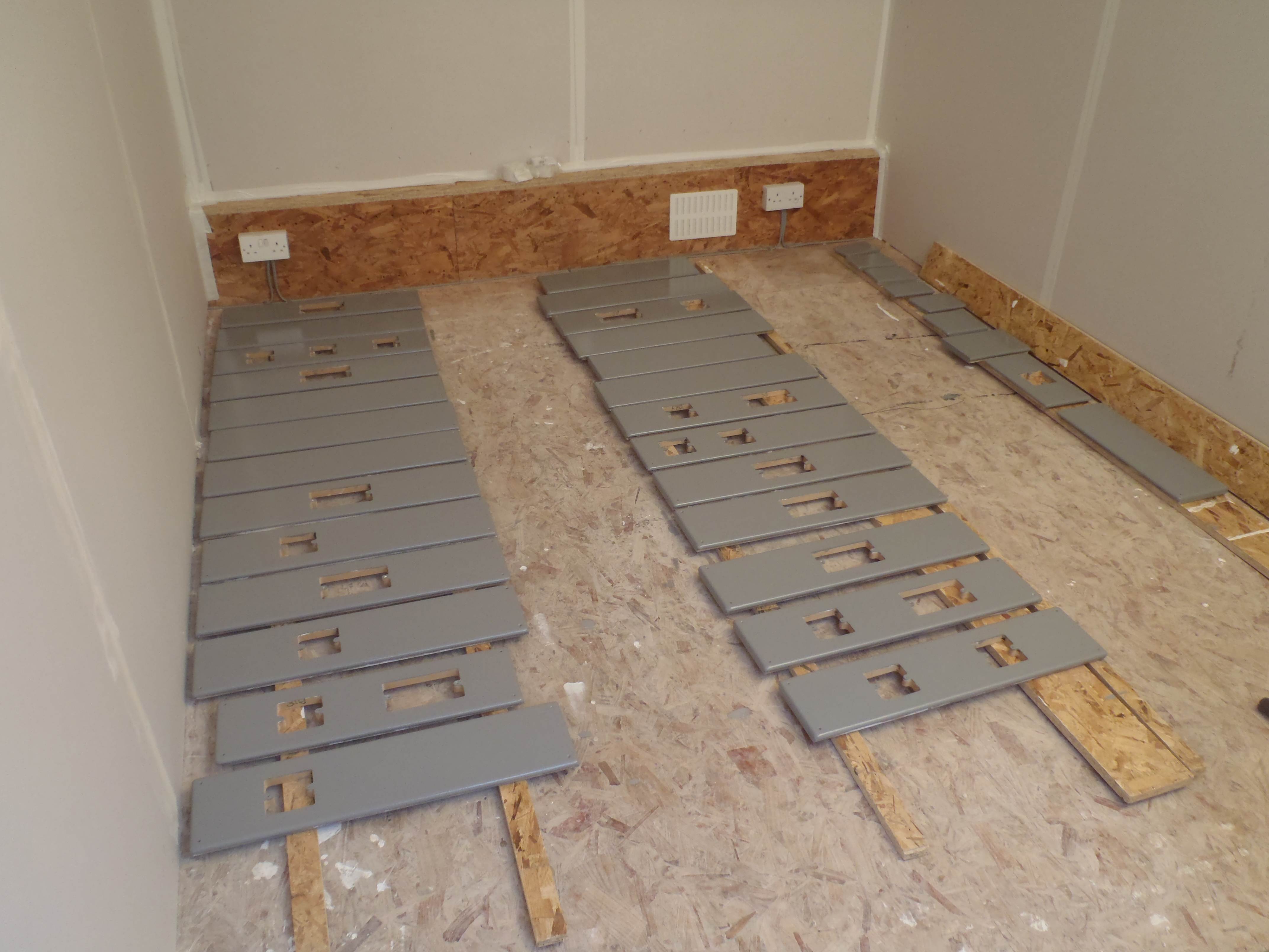
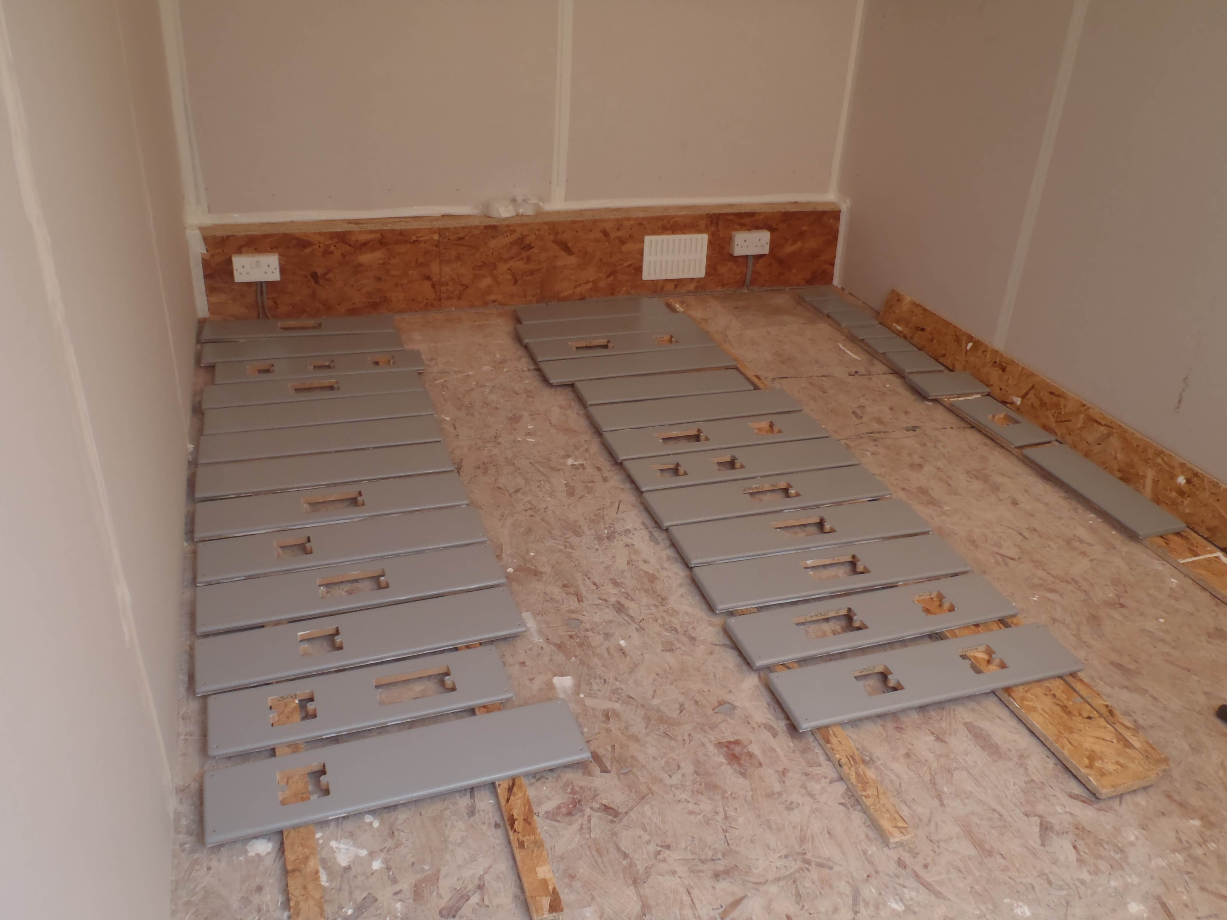
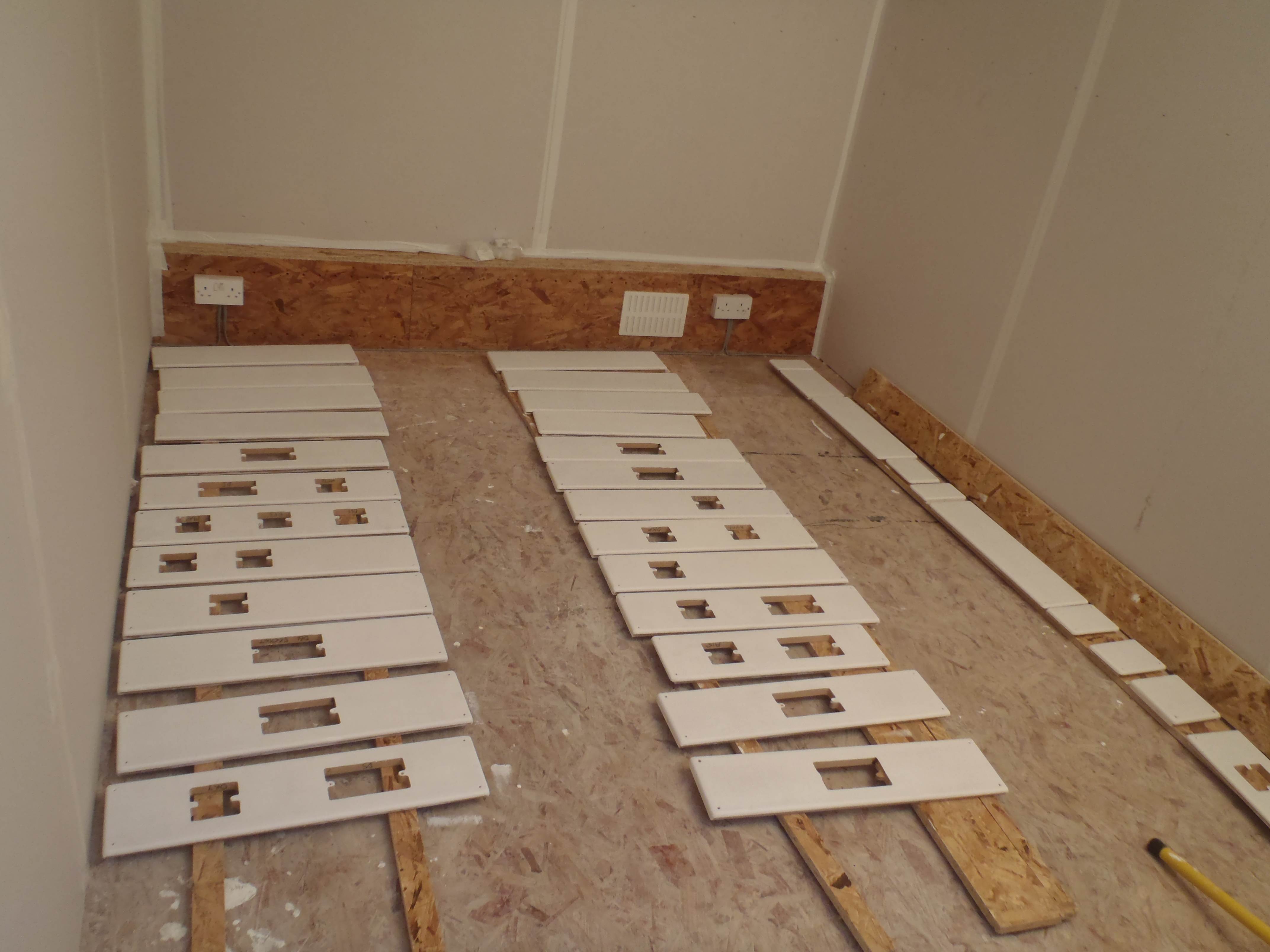
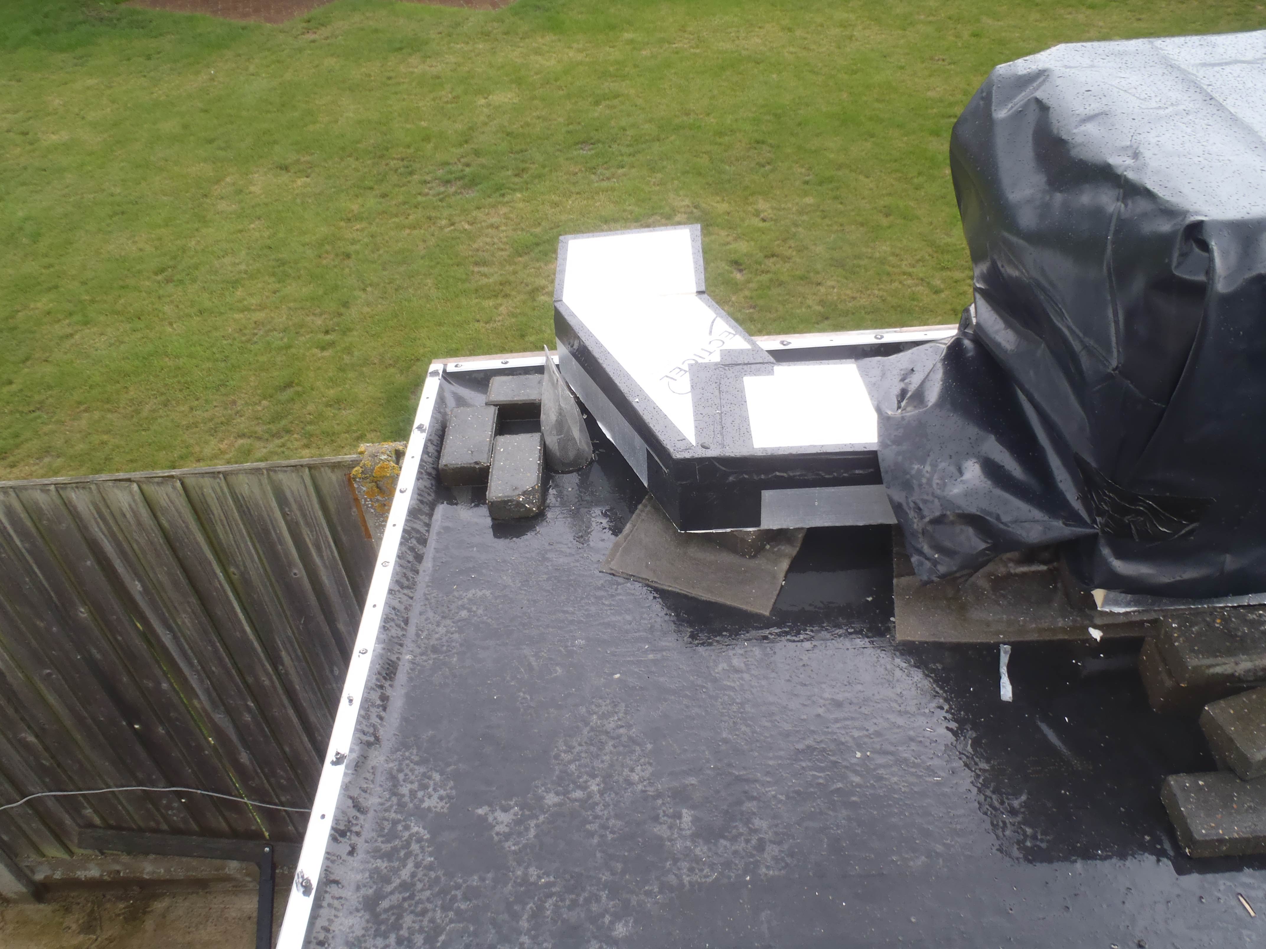
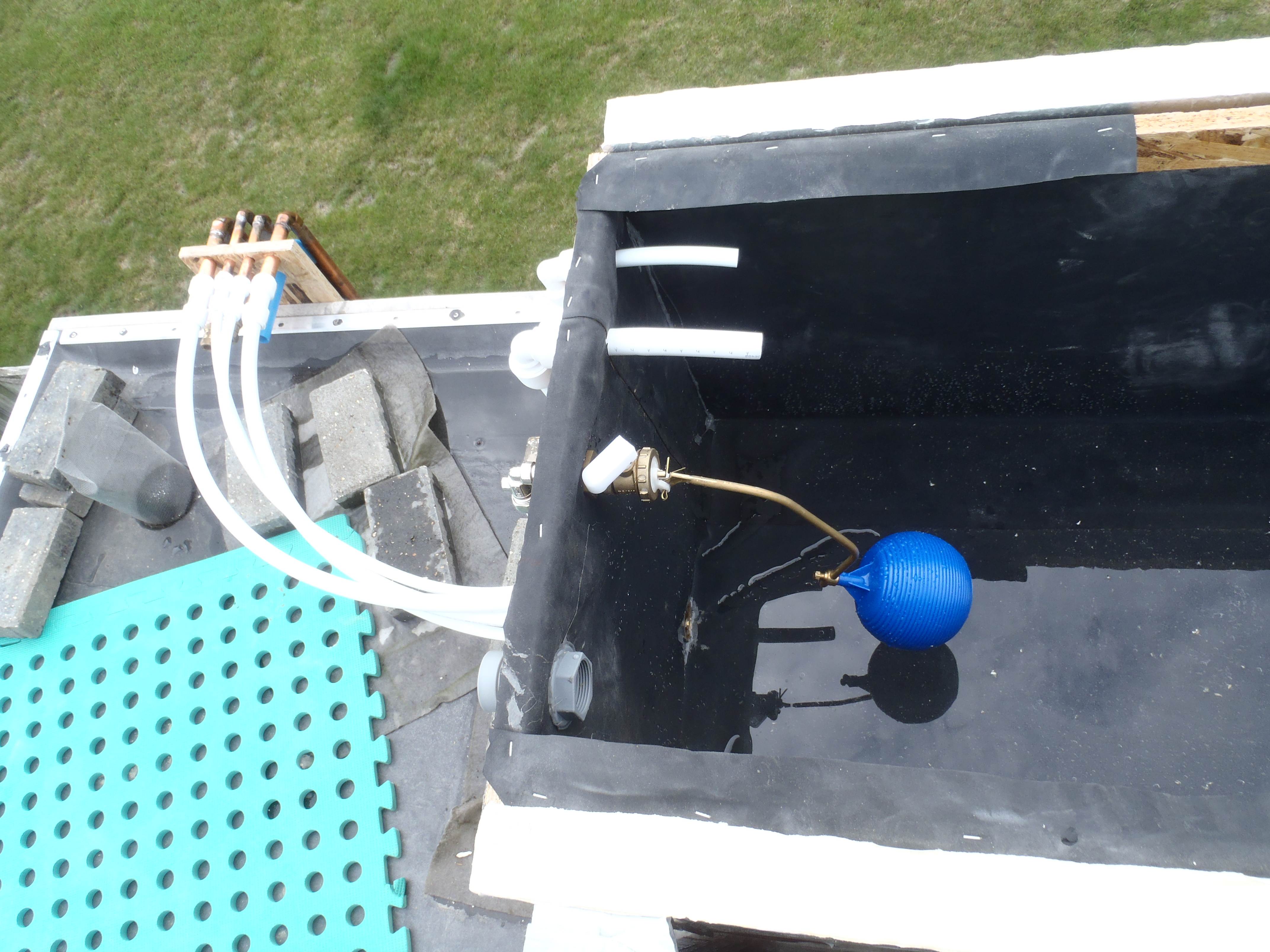
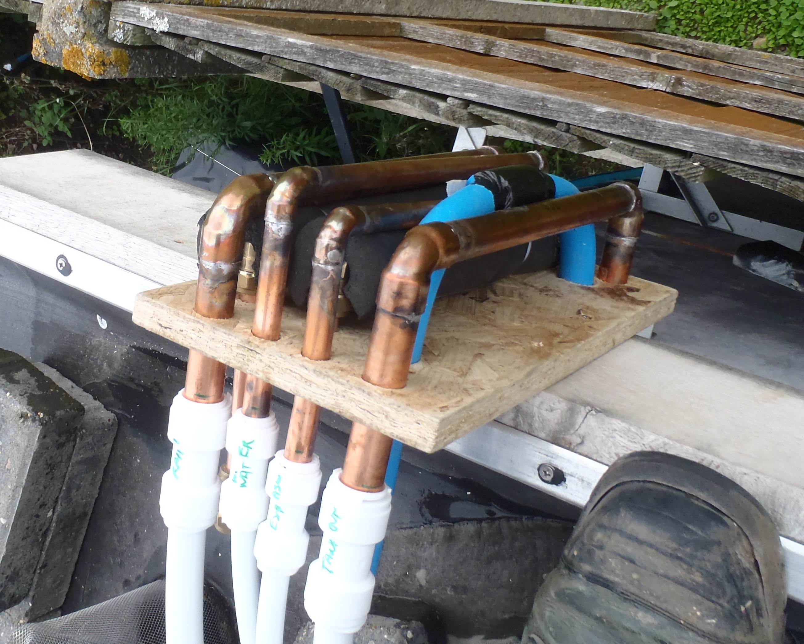
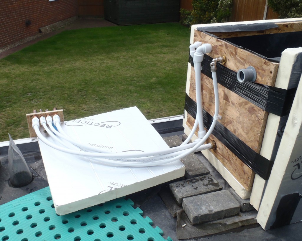
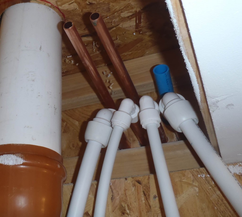
The finished special “U” pipes for the roof was installed today. Then connected the 4 cold water pipes inside above the hot tank, the mains water, the rain tank feed, the hot tank expansion overflow and finally the header tank down feed. Then went up on the roof to connect the other half, the other side of the “U” bends and bring the 4 pipes to the header tank itself.
Apart from one air lock situation, the header tank filled up nicely, the hot tank was filling up, water was coming out of the basin pipes! The air lock occurred in our “U” bends we think and we got rid of it by getting the garden hose up to the header tank and blasting mains pressure down the cold water feed from the header tank! One loud gurgle later and everything resume flowing quite nicely thank you! It is very interesting in how the slightest angle off a pipe might end up that would cause an air lock. Amazing!
While the header tank was filling up we fitted the basin in the toilet.
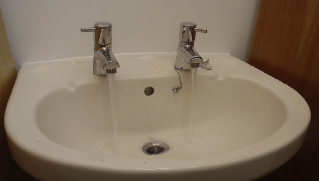
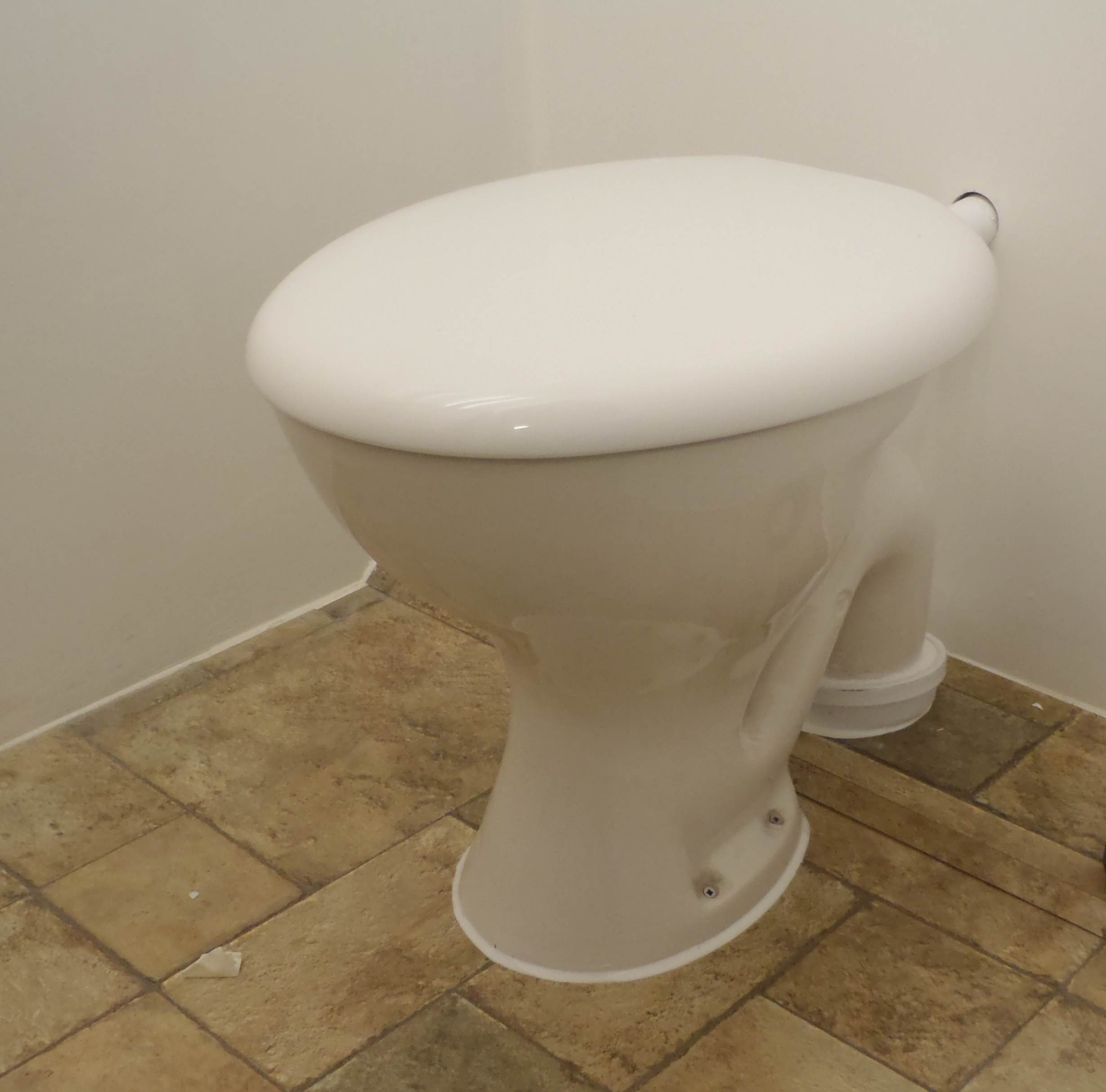
And also we installed the toilet pan too!
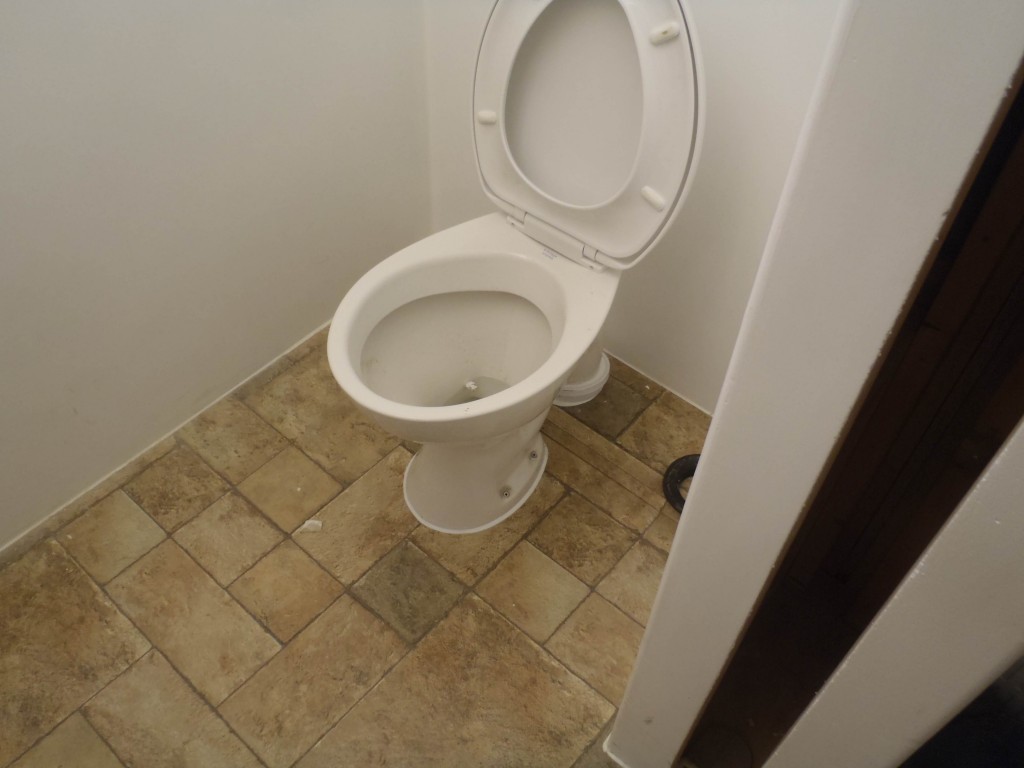
We now have water in our basin, from both taps but both cold! For now! The cistern fills up too but we haven’t pulled the handle or rather in this case push the button! We wanted to make sure the sealant is fully cured around the soil pipe connections before subjecting it to too much water, but tomorrow .. .. we will definitely christen it! Smile!
we carried on making the “U” shaped set of pipes to take the various water pipes up to the roof to the header tank and to our future solar water collectors. A mixture of 15mm copper (4 pipes) and 22mm copper (2 pipes) plus one plastic electric conduit. They go out through 7 holes out of the back wall above the hot water tank, bend upwards to pass the Oak Facia board and bend back onto the roof.
Today we have finished soldering 4 of them and screwing together the other 2 copper pipes (the last 2 pipes has to withstand high pressure and temperatures so soldered joints of the standard lead/tin kind isn’t strong enough). We bent the plastic conduit (25mm) by heating it up using a hot air gun and pushing inside one of those 22mm diameter coiled springs to help keep the walls from crumpling up and bending it on a jig!
Tomorrow we can put it up and start connecting the mains water to the header tank and the see if it works!!