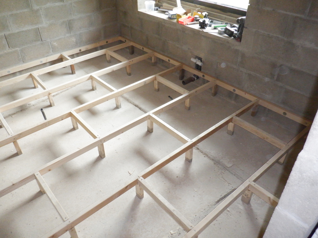
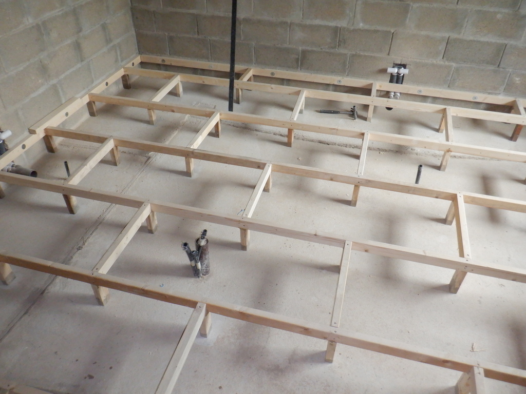
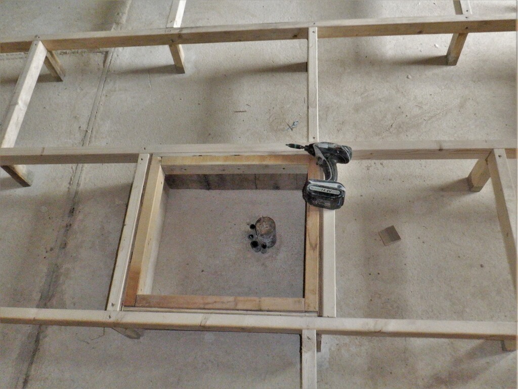
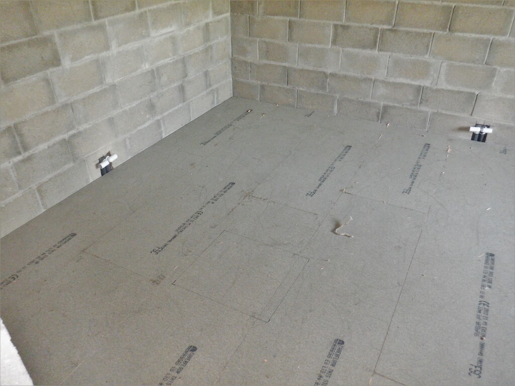
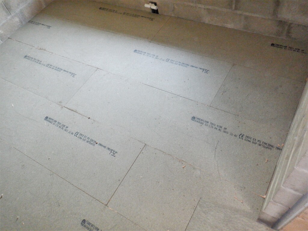
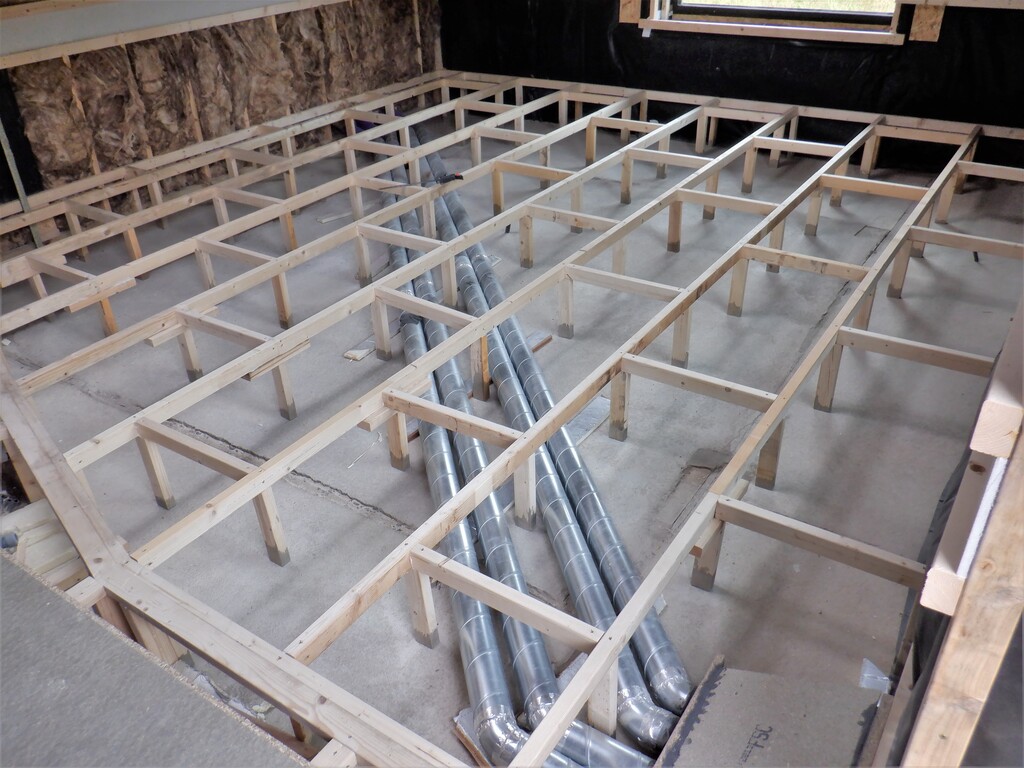
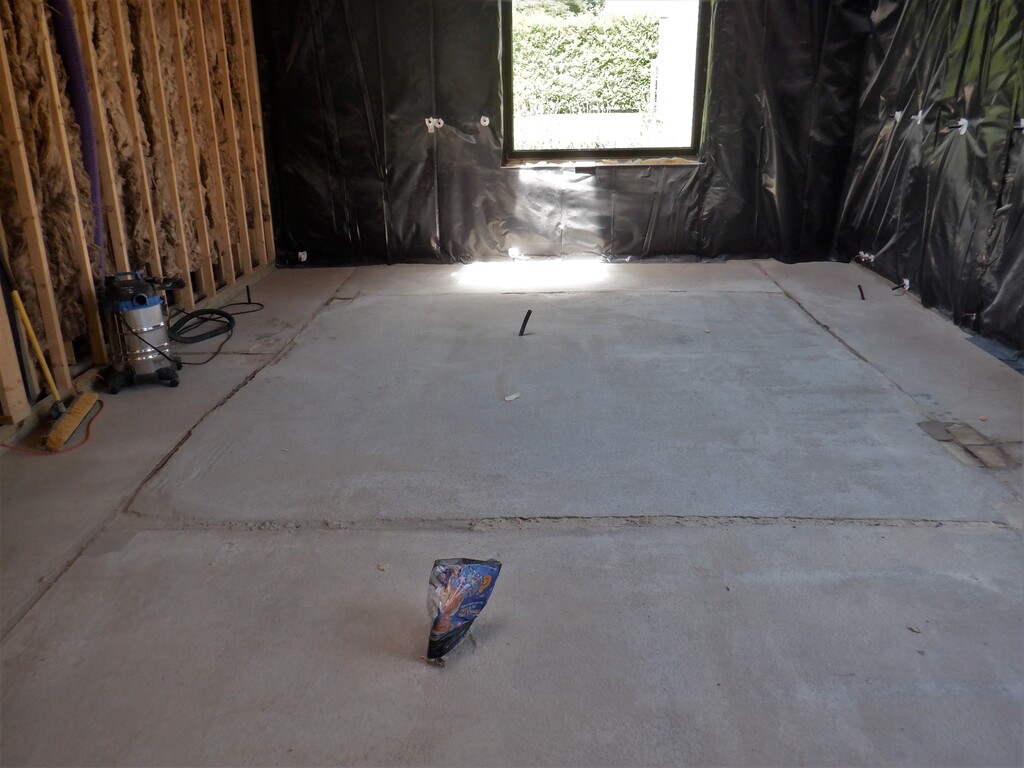
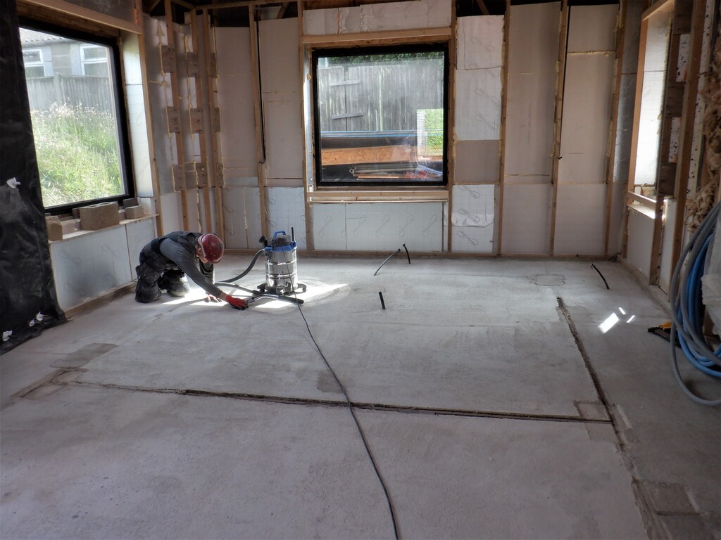
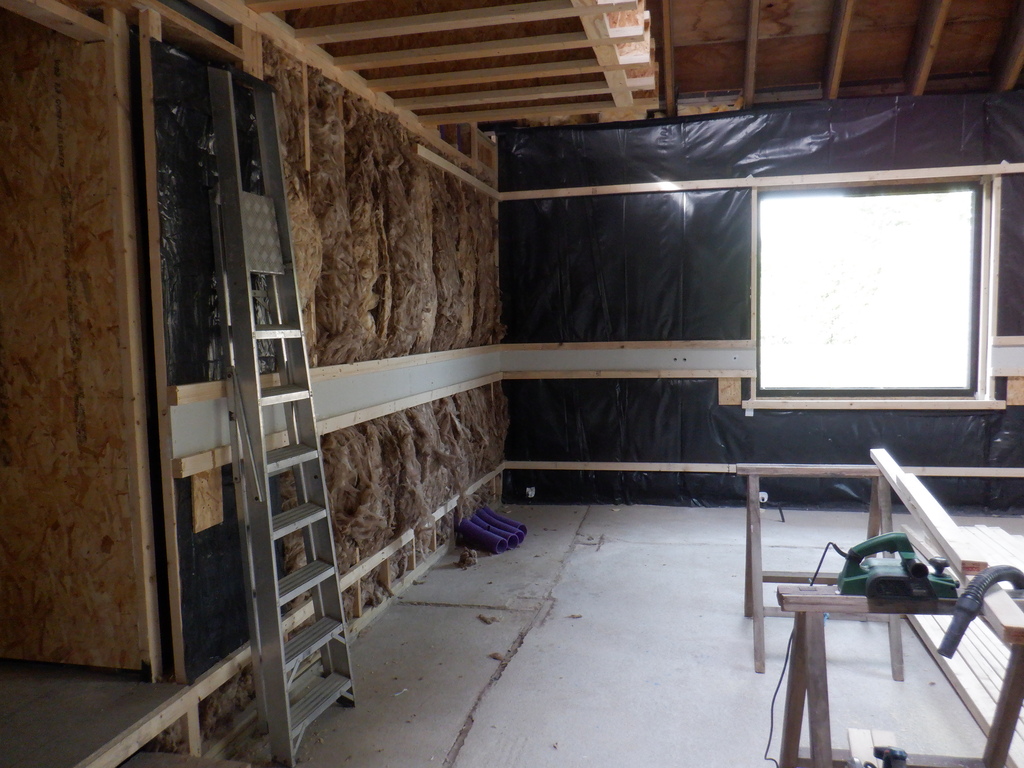
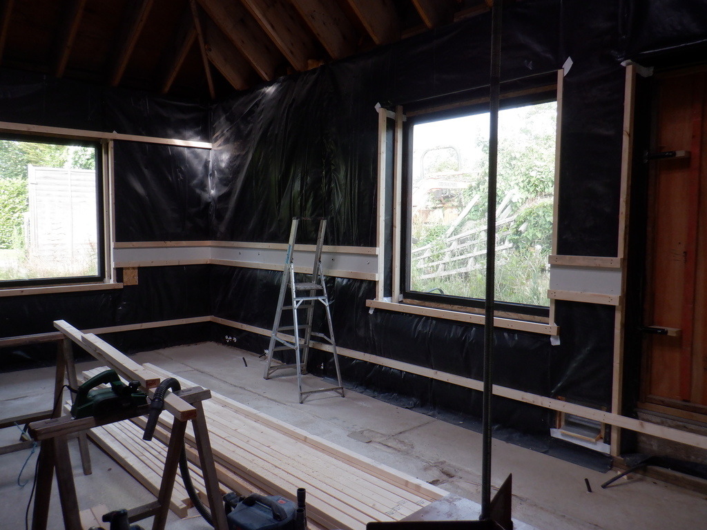
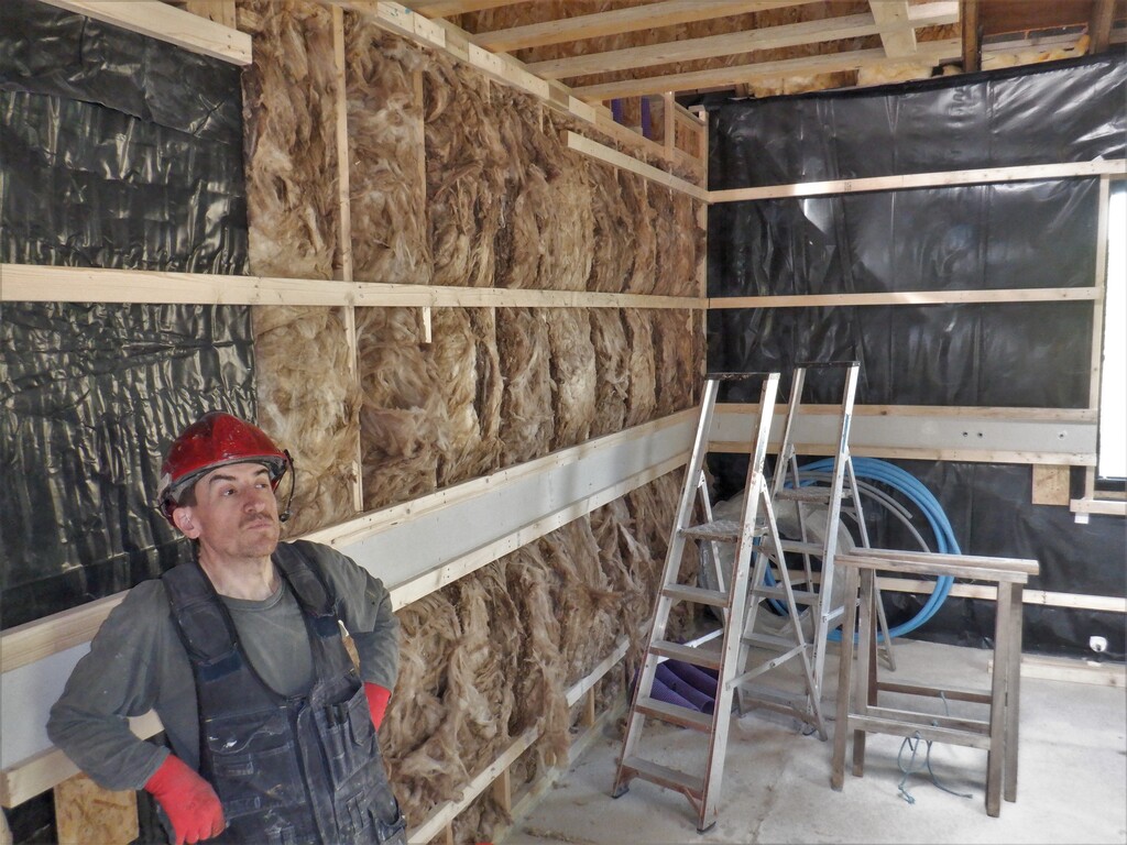
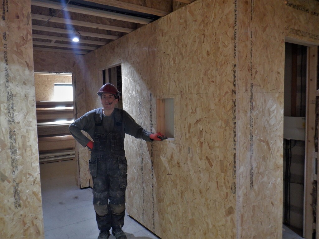
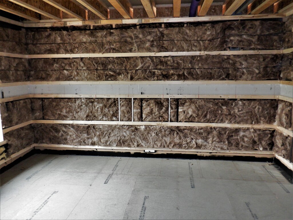
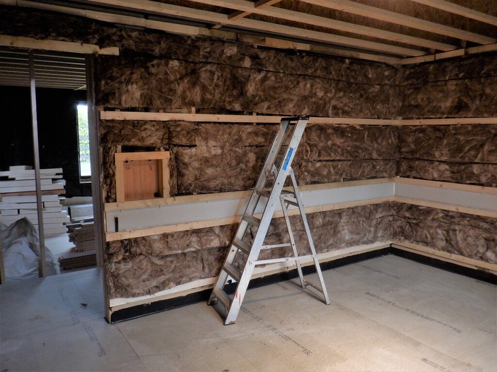
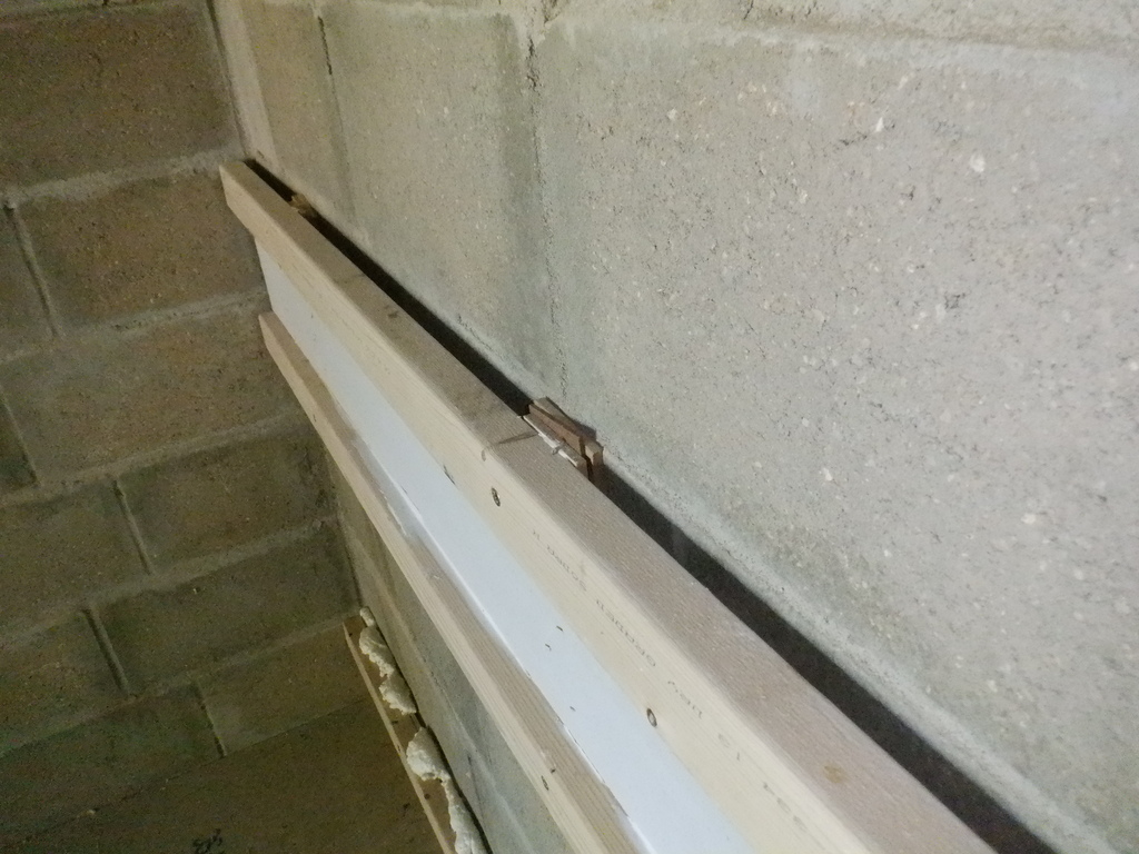
We started working on constructing the Walls inside the Entertainment Room, now that we have done the floor. The concrete block walls are a bit (well actually up to 15mm) wavy so we had to mount our horizontal rails with various thicknesses of wooden shims, to pad out the gap between the CLS rail and the concrete wall, when the rail is made aligned using our green laser line generator. We started on the shorter wall opposite the window so we could learn how things went together before we tackled the long stretch of the wall. We screwed the laser down into the left corner to the floorboards and got the green laser 55mm from the surface in both corners, left and right both. We worked from top down, putting the first rail up near the ceiling, but with enough space to allow a 11mm OSB sheet to fit into the small gap so the ceiling is supported around the edges of the walls.
But before all that, we had to make dozens of different sized wooden shims, using various left-over sheet material we had lying around. We made 18mm OSB ones, 13mm Plywood ones, 6mm MDF ones, 3.6mm hardboard pieces and we found some odd 6.5mm thick MDF ones so they got included too. Plus also, we sliced up some very thin plywood that are 1.5mm thick to help with the final slight adjustments. We bought the other day a new kit of plastic spacers (also known as shims or packers), they come in 1mm, 2mm, 3mm, 4mm, 5mm and 6mm so they will be there if we run out of our wooden spacers.
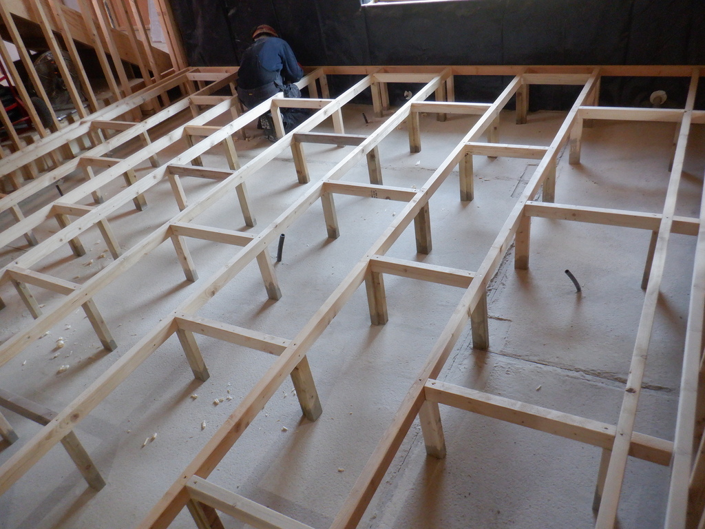
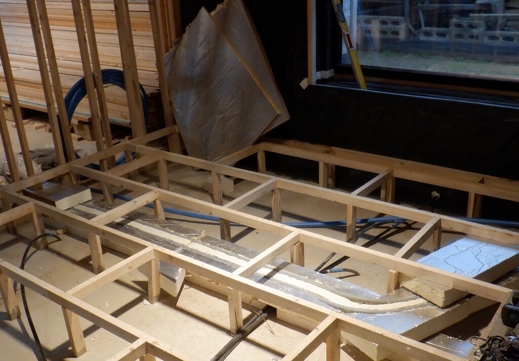
So, we cut a piece of CLS timber to 3.76metres long and drilled 7mm clearance holes every 600mm along the rail, with them all offset by 300mm from one end. To make sure that we maintained a constant gap at the top there, we screwed some 12mm plywood pieces up on the ceiling so it would automatically produce the correct spacing when we pushed the rail up there and drilled the holes into the concrete. We drilled 7mm holes using our trusty SDS battery drill which made short work in drilling 70mm deep holes!
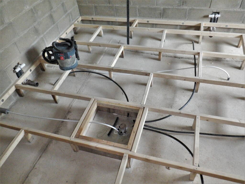
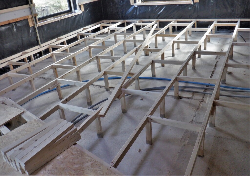
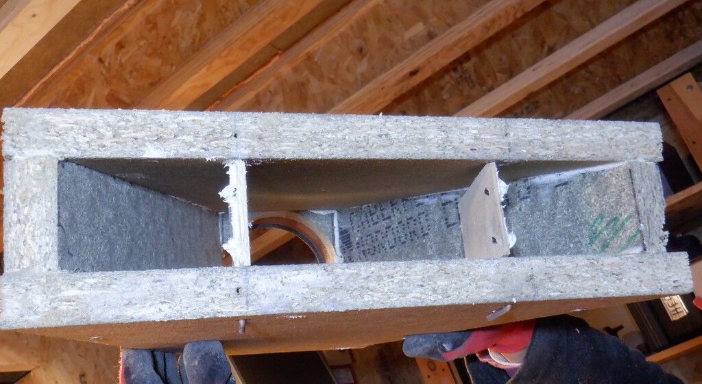
Then, we tightened the wooden rail into place using 100mm 6mm thick screws, putting a variety of different combinations of the wooden shims behind the rail until the green laser line just shimmed across the surface. We repeated this process for the mid rail and then we constructed the Utility Channel completely on the floor before mounting it up on the wall. We made 300mm long pieces of MDF strips which bridged across the two CLS rails that makes up the Utility Channel, gluing and stapling each strip over where the screws will go. Then, we glued and stapled the fermacell board strips in between, and glued to the bridging pieces.
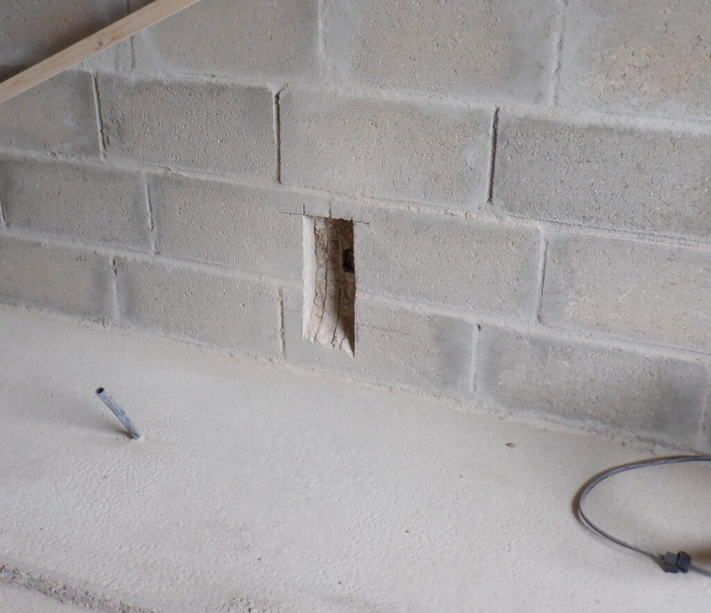
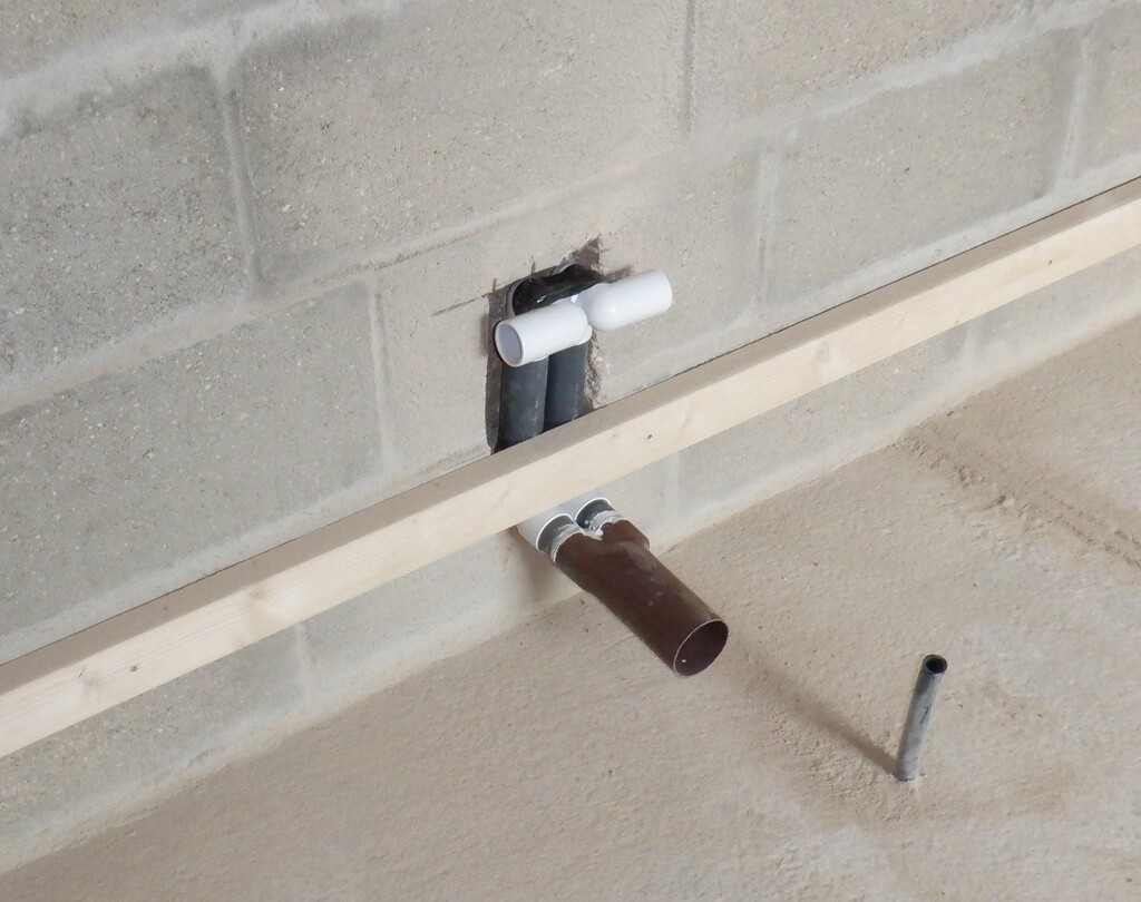
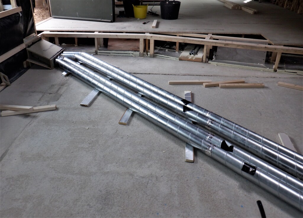
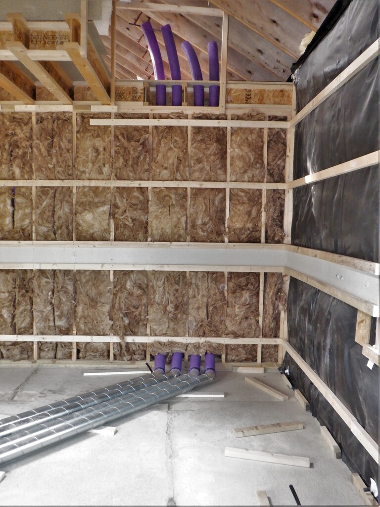
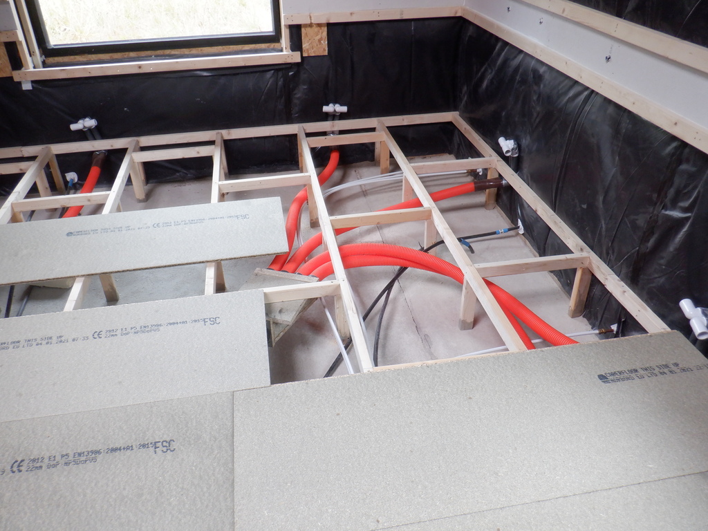
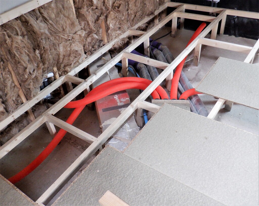
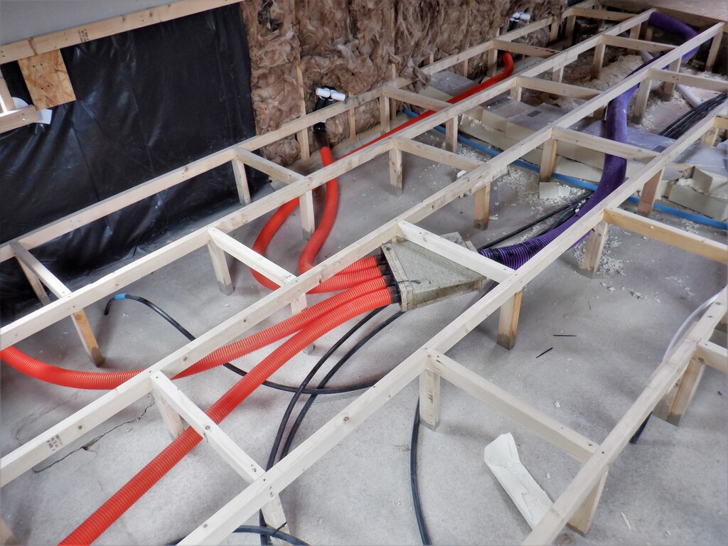
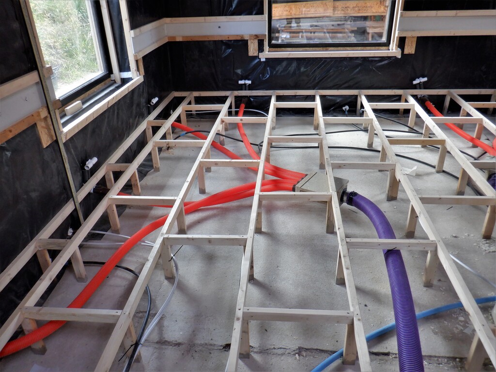
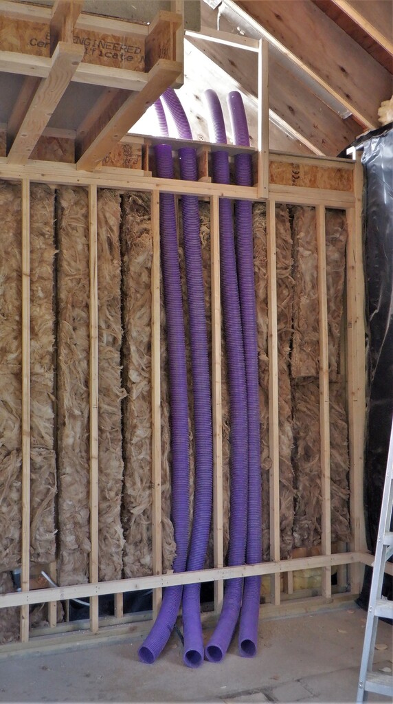
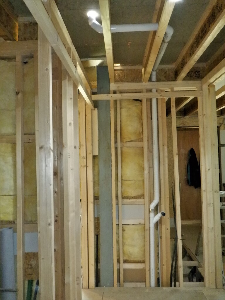
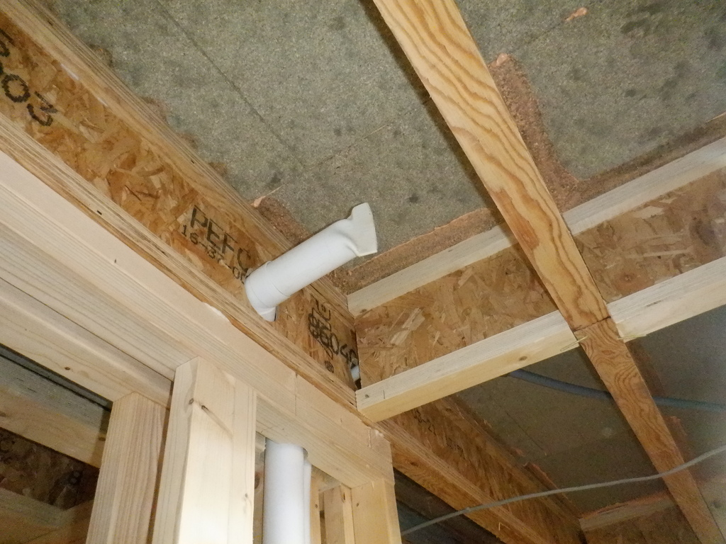
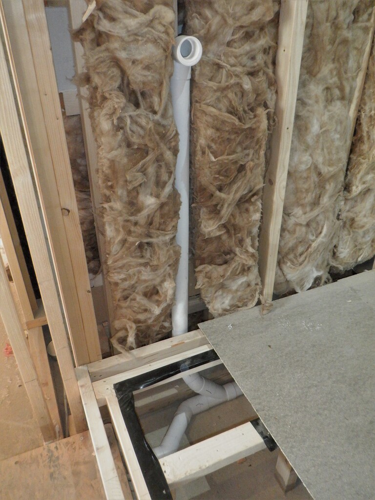
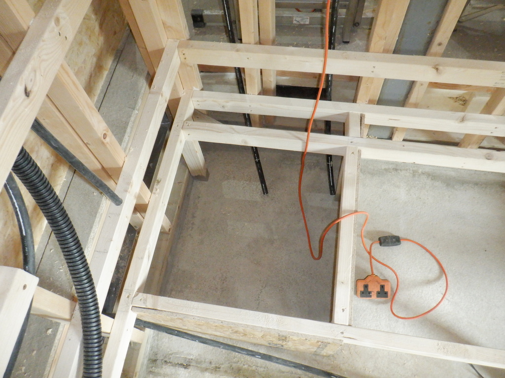
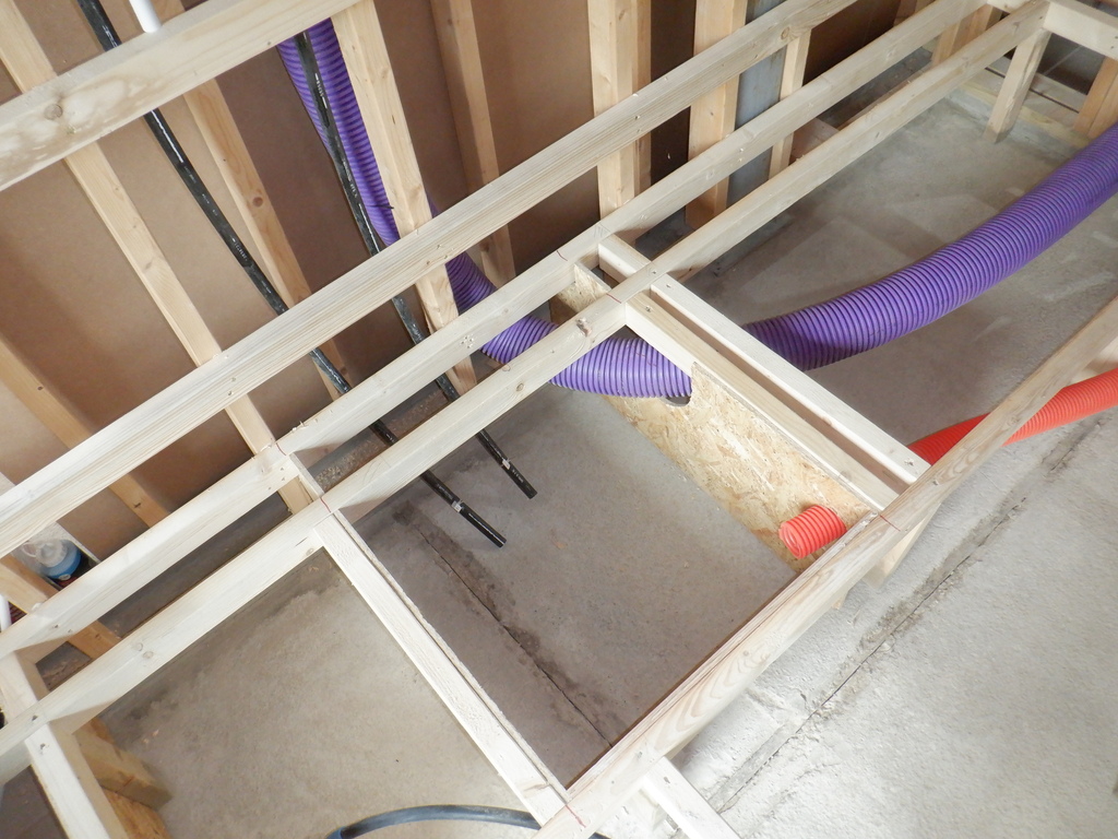
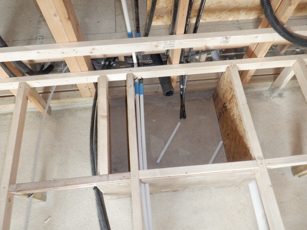
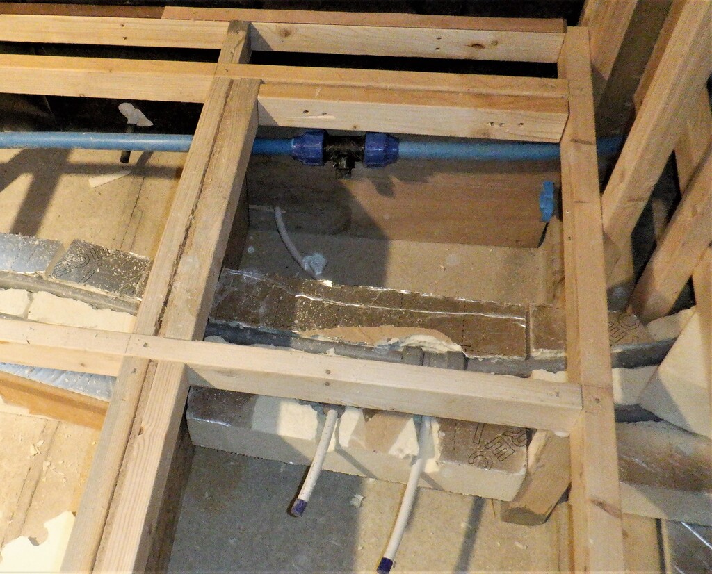
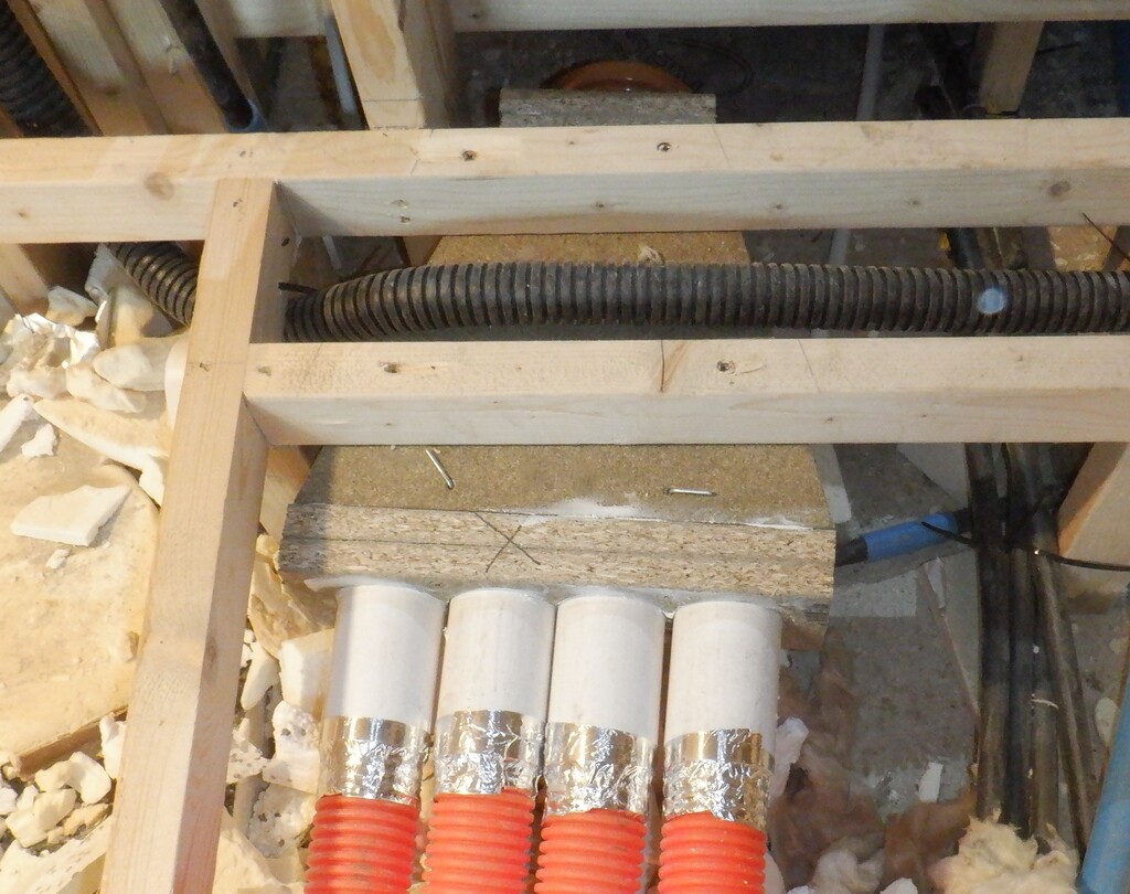
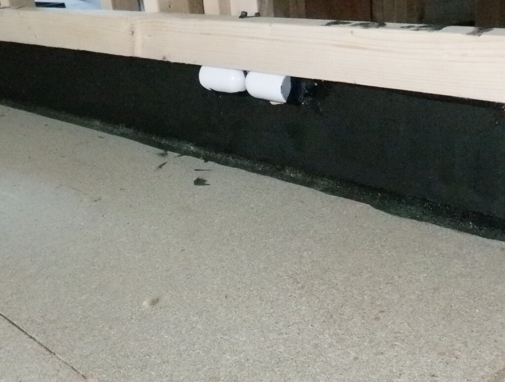
Constructing the Utility Channel like this meant that we didn’t have to mount each rail separately and the whole length could go up on the wall in one go. The final rail to put up is the Air Channel, which was constructed completely separately like we had just done, but this time, using our 150mm MDF strips to form the channel for the air to flow sideways and into our room. The Air Channel just sits on the floor surface so that was relatively easy to mount it to the wall. The final step was to spray lots of PU foam behind the Air Channel and also behind the plastic pipes that comes around from below the floorboards via a deep slot in the concrete wall.
Assorted-spacers-aligning-rails-on-the-wall
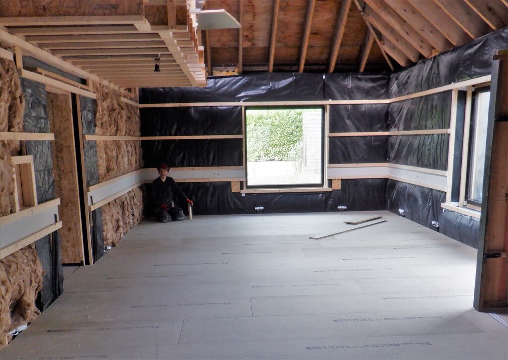
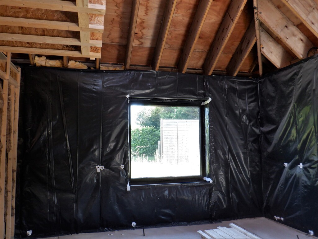
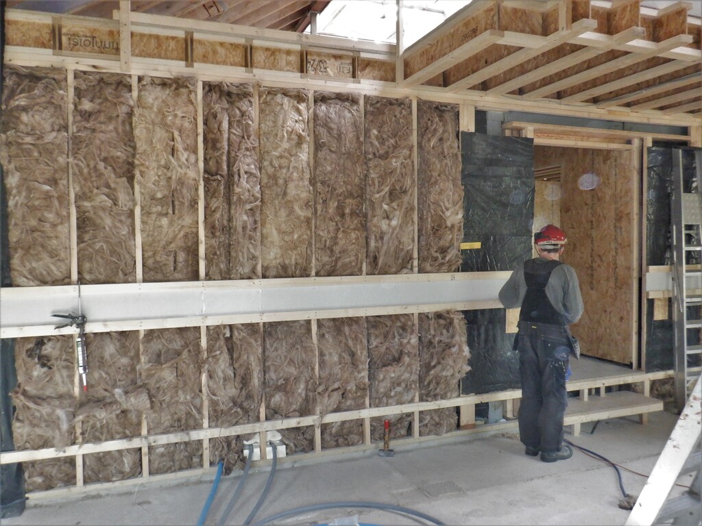
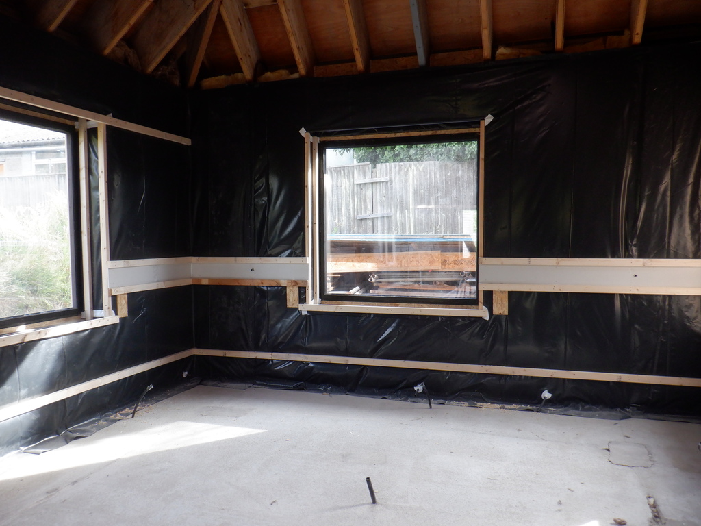
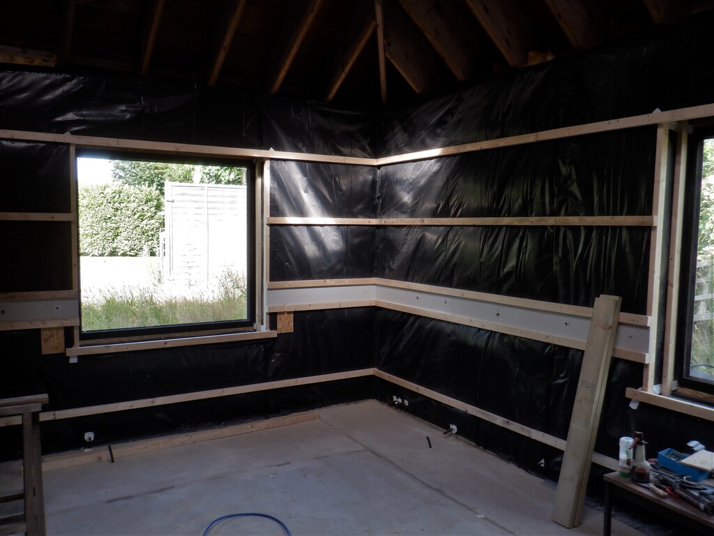
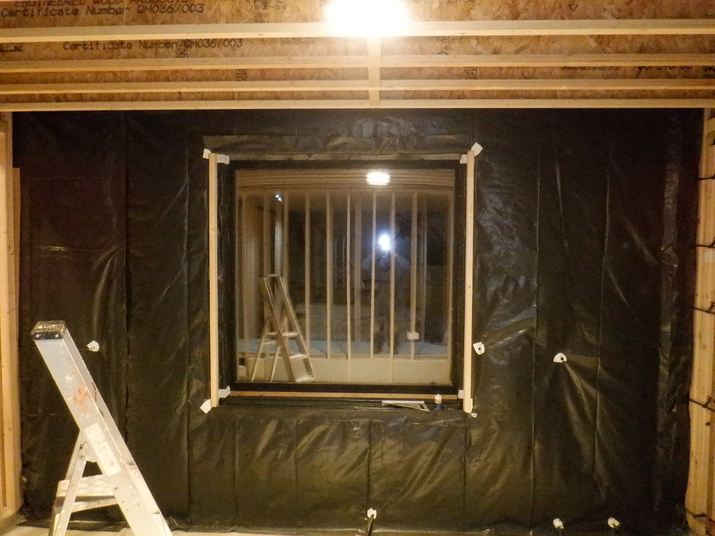
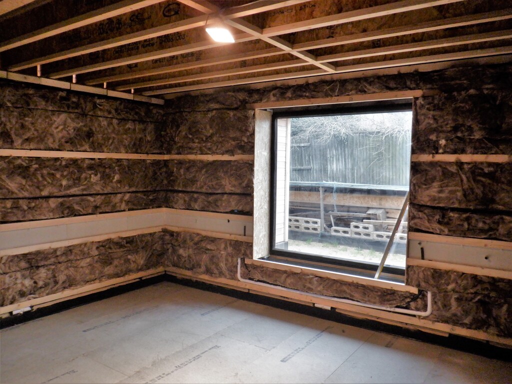
We repeated this process for each of the other walls, including tackling the window wall and putting up enough wooden rail to form a very narrow strip above the window. With the lowered ceiling level, the height of our standard windows, being seven foot high, meant that the resultant ceiling is almost level with the top of the window, the narrow strips will be something in the order of 60 to 70mm wide. Just enough to allow for traditional curtains to be mounted across the window if we wanted too. We had to put up a 50mm square piece of timber, instead of our regular 63mm CLS timber but it worked out very well, especially that we had put up two extra layers of 89mm CLS planks behind this rail, to help reinforce and support it. We glued it using our top quality PU construction glue, and clamping the pieces all together including pushing upwards to stick to the concrete beam that is going over the window like a lintel.
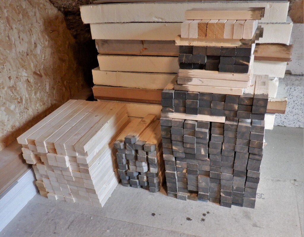
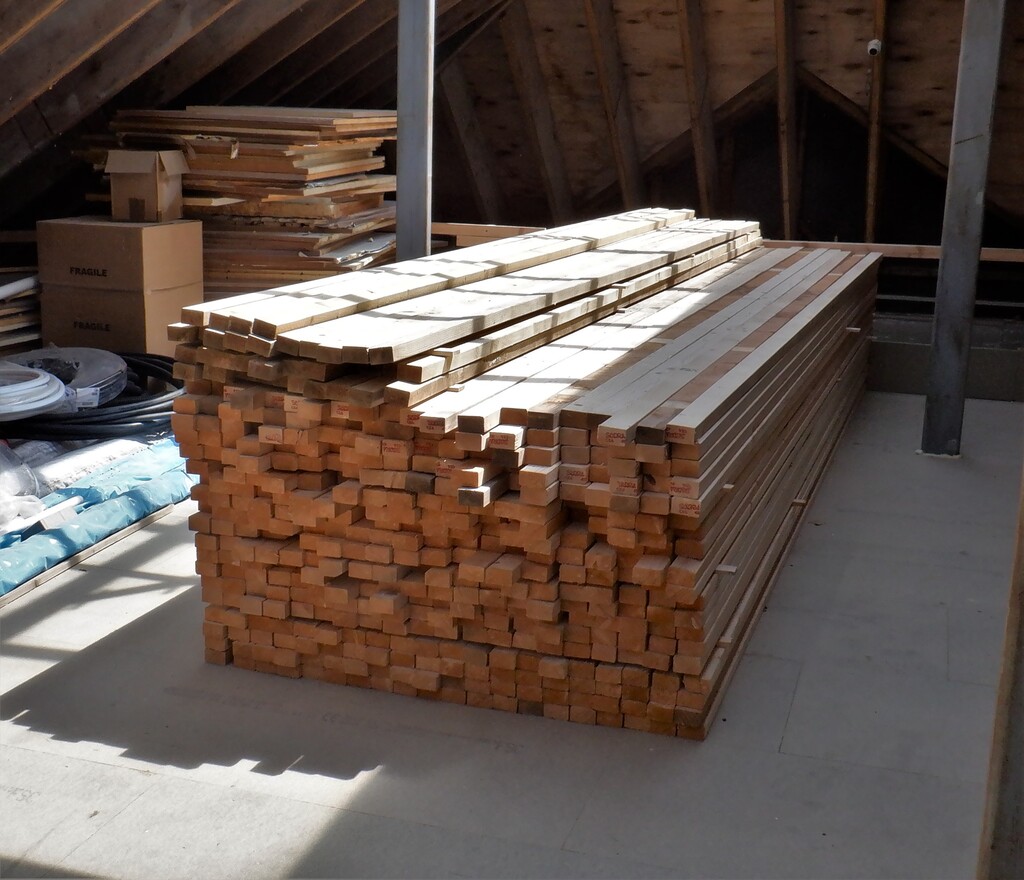
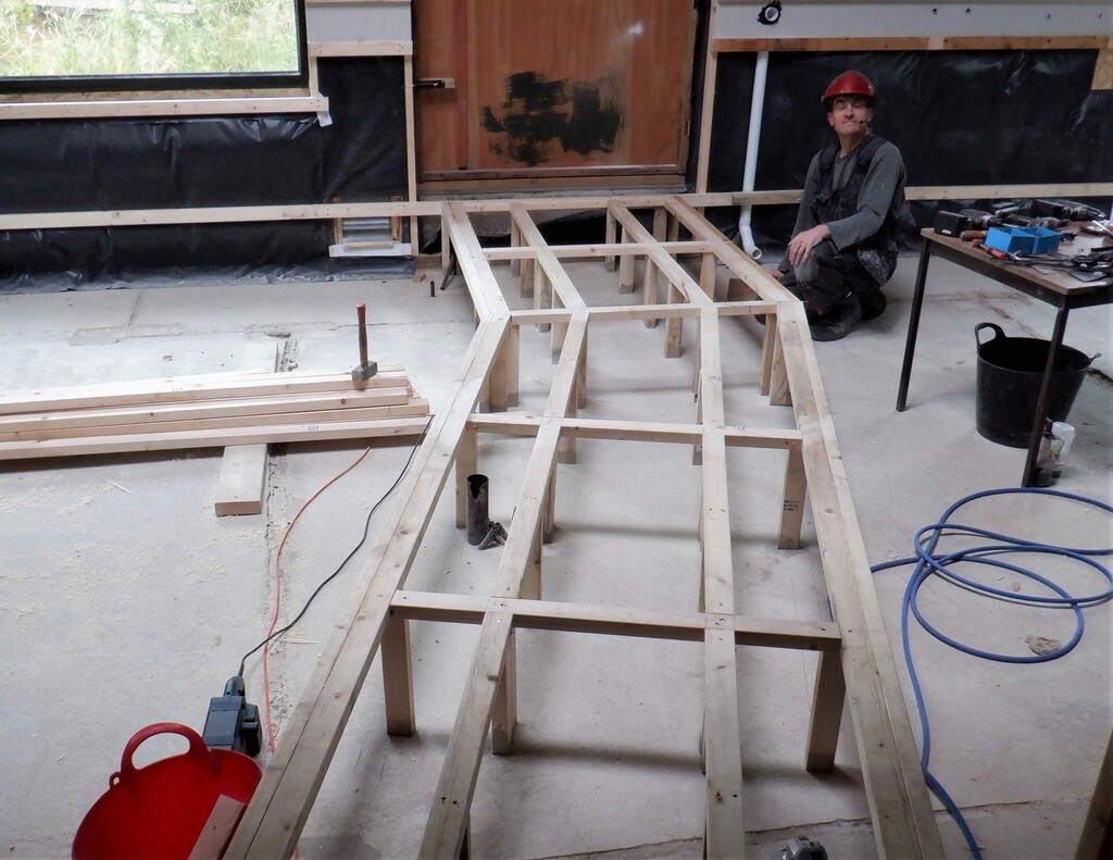
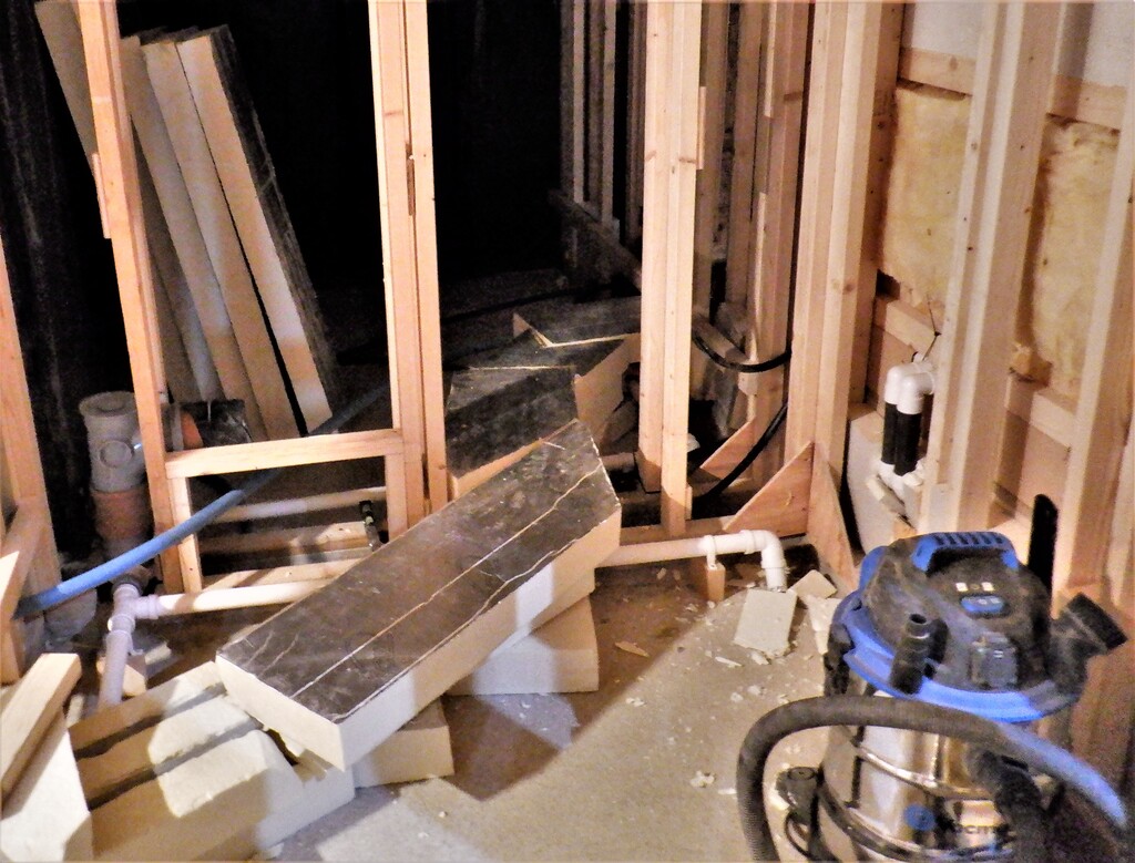
We finished putting up the rails on either side of the doorway, just like the other walls, with a small extra bit sticking into the entrance way. This allows us to set the laser green line to be vertical and aligned to the hall side of the doorway and find out whether the concrete blocks are straight or not. And, of course, they are not quite vertical! They are leaning askew by 5mm or so at the opposite end, depending on whether it is the left or right hand side of the door. In fact, we had already made the hall side of the entrance square and vertical so that gives us something to measure against and make any adjustments. We took one of our very old wooden planks that we had stored on our wood rack, a “2 by 6” rough sawn conifer timber plank, a 4.8metres long. We think we had originally bought these pieces of timber back in the mid 2000’s and we knew that we would reuse them again .. one day!
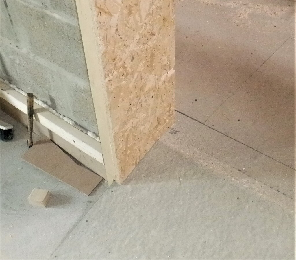
We are using these 150mm wide planks to help reinforce the door frames, so that we can mount a heavy weight door to help block the sounds from escaping the Entertainment Room. So, after slicing off the excess bits off each of the horizontal rails, we then discovered that the gap between the ramp and the concrete blocks wasn’t quite big enough to fit the 50mm thick plank so we had to trim slivers of wood off the timber until we could insert the plank down pass the ramp and with a notch to avoid the floorboards, to rest on the concrete blocks that is running underneath the doorway. After making careful adjustments, using the laser level and our digital spirit level as well, we then drill five holes in each vertical planks and then drilled nice deep 80mm holes into the concrete blocks too, just like what we have been doing to fix up all our wall rails too. We put in various shims behind each screw and ensured that they were nice and vertical, on both sides of the doorway. Once we were happy, we unscrewed everything and applied loads of PU construction glue all over behind the plank and all over the concrete blocks and redid the screws and got the planks fixed down nice and tight, all smooth and level to the front of the wall rails.
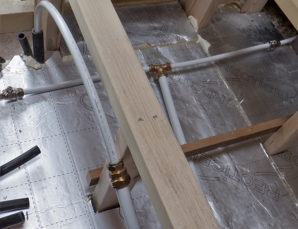
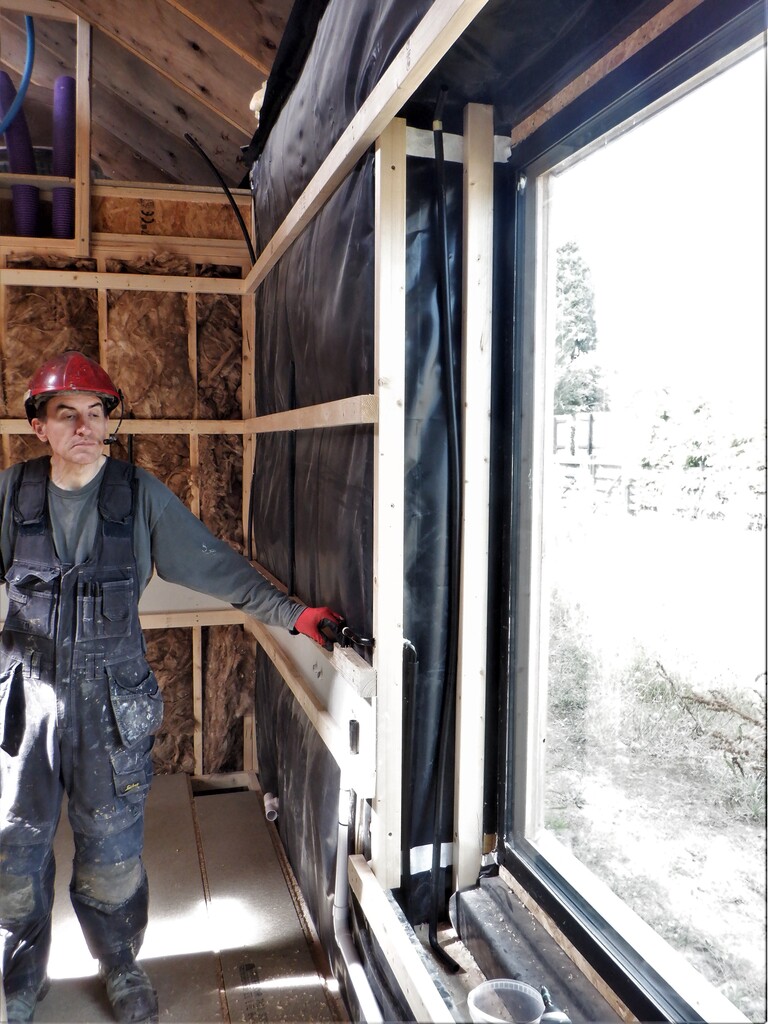
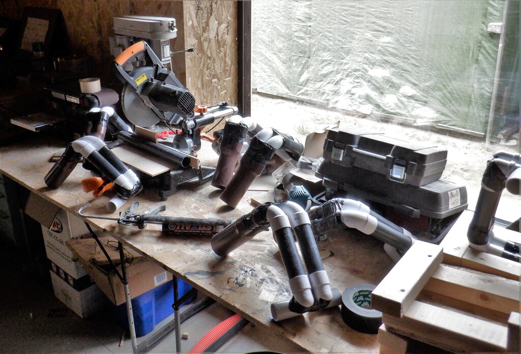
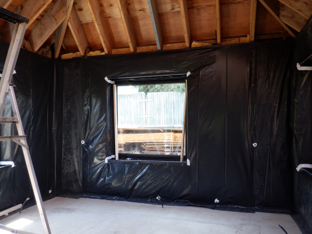
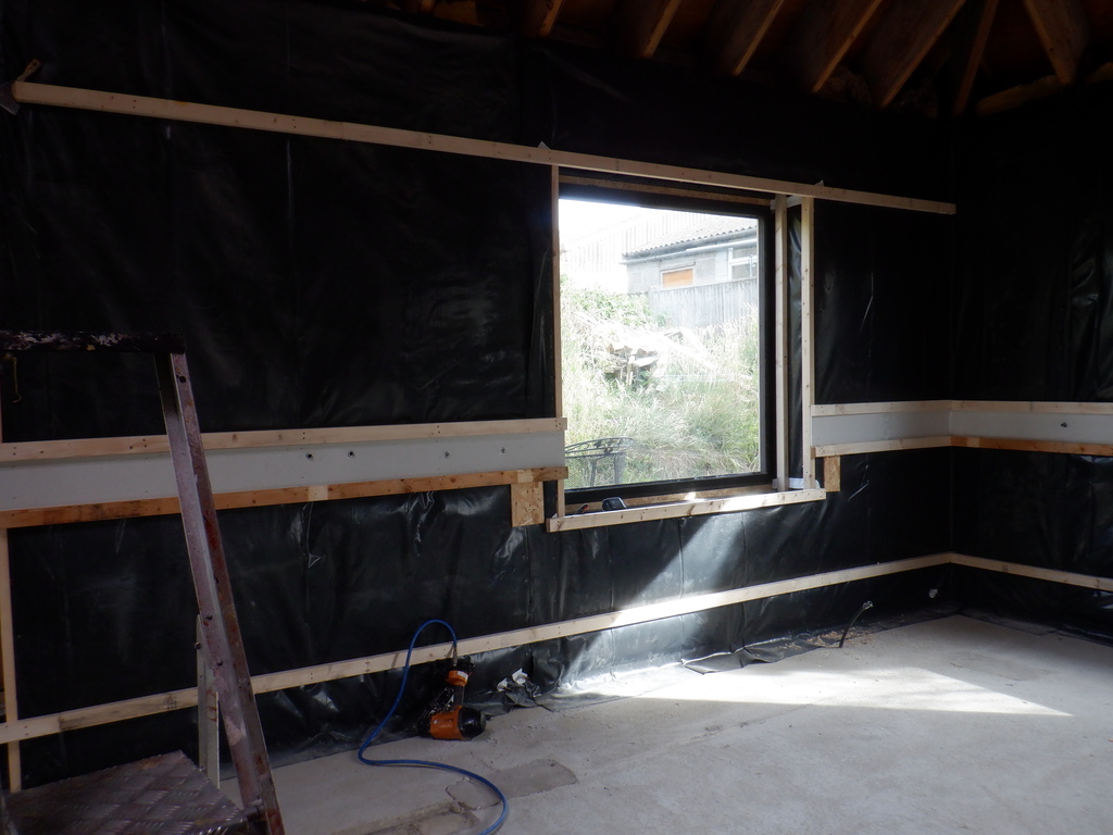
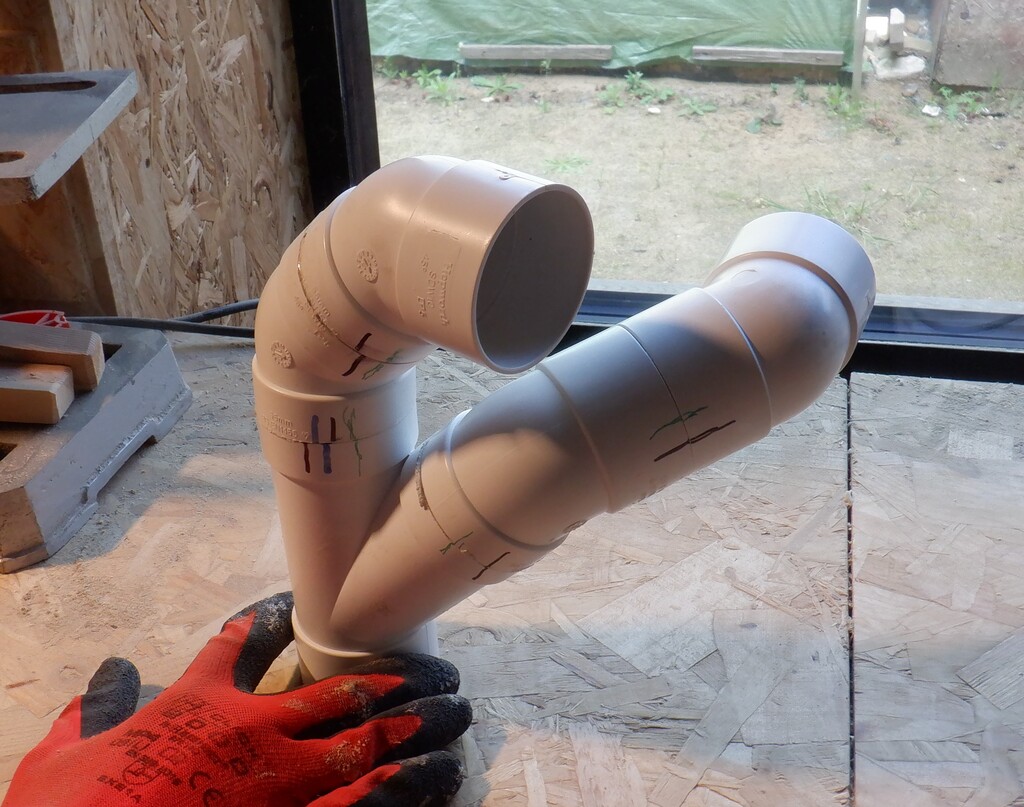
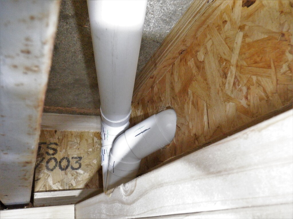
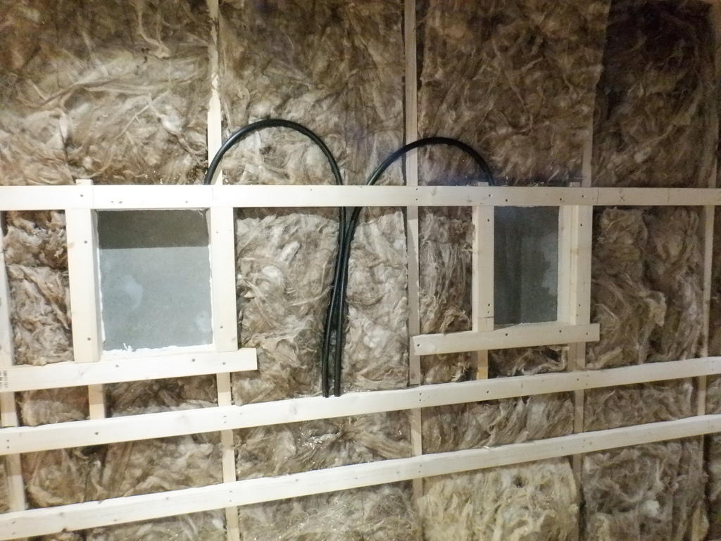
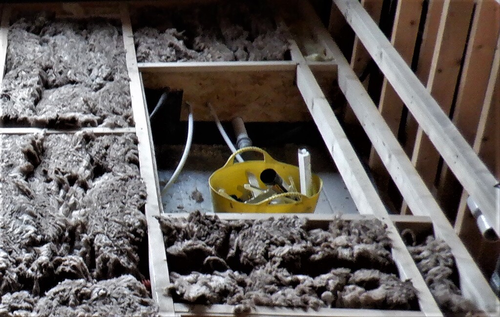
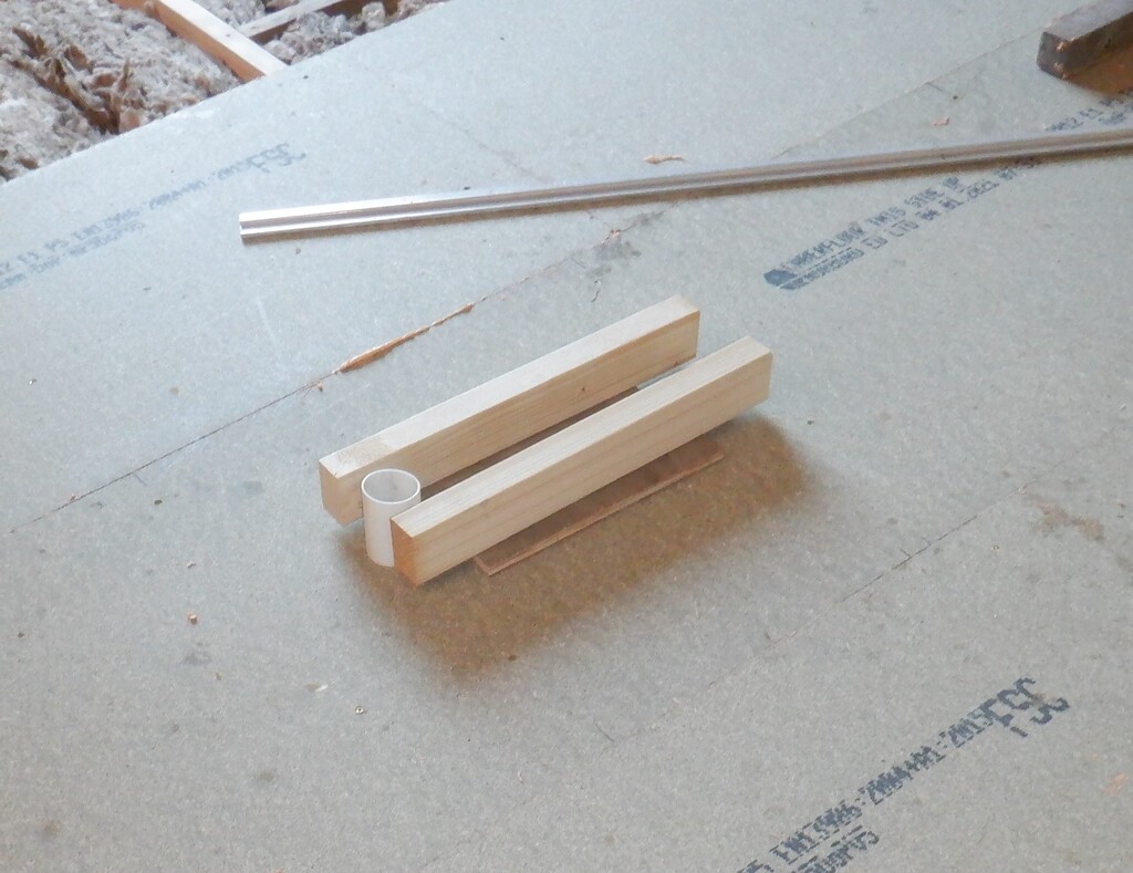
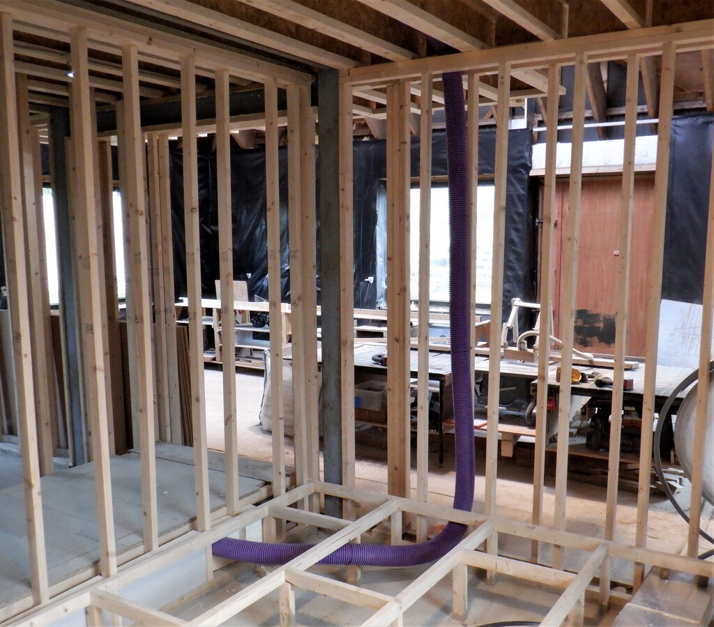
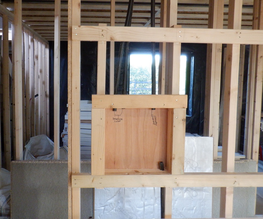
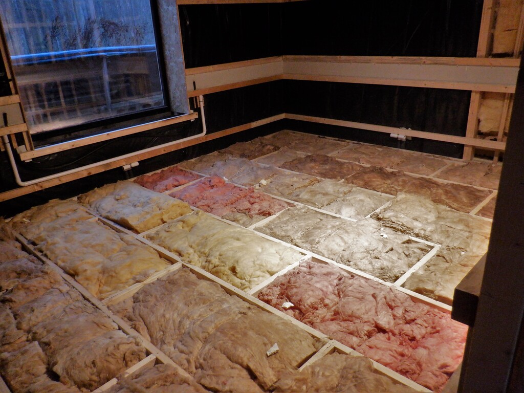
We had also done something quite similar to our window, putting in a CLS piece of timber so it was square to the glass, anchoring it with screws from the front through our wall rails and then trimming off the additional extra bits of the rails that were sticking into the window space. Next, we took a length of 20mm plastic conduit pipe and bent it at four measured locations which enabled us to feed some wires from the Utility Channels and down into the space underneath the window sill, to power and control the window blinds.
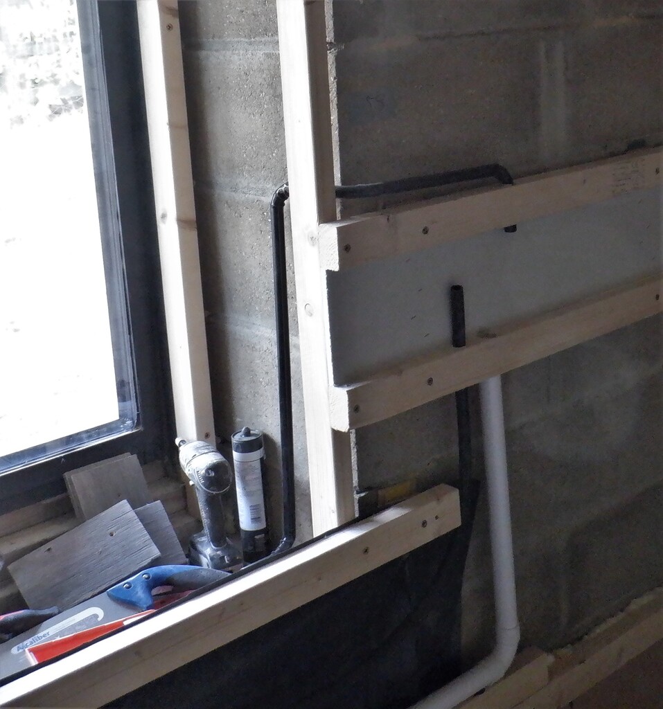
Entertainment-Room-Window conduit
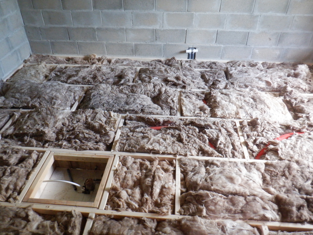
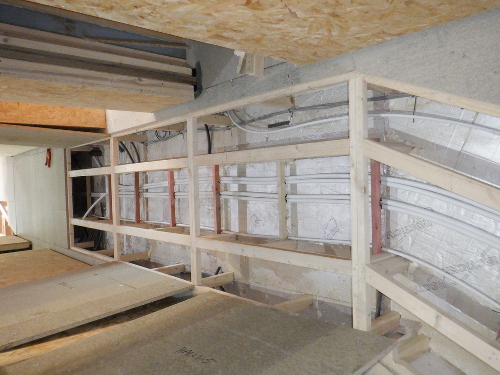
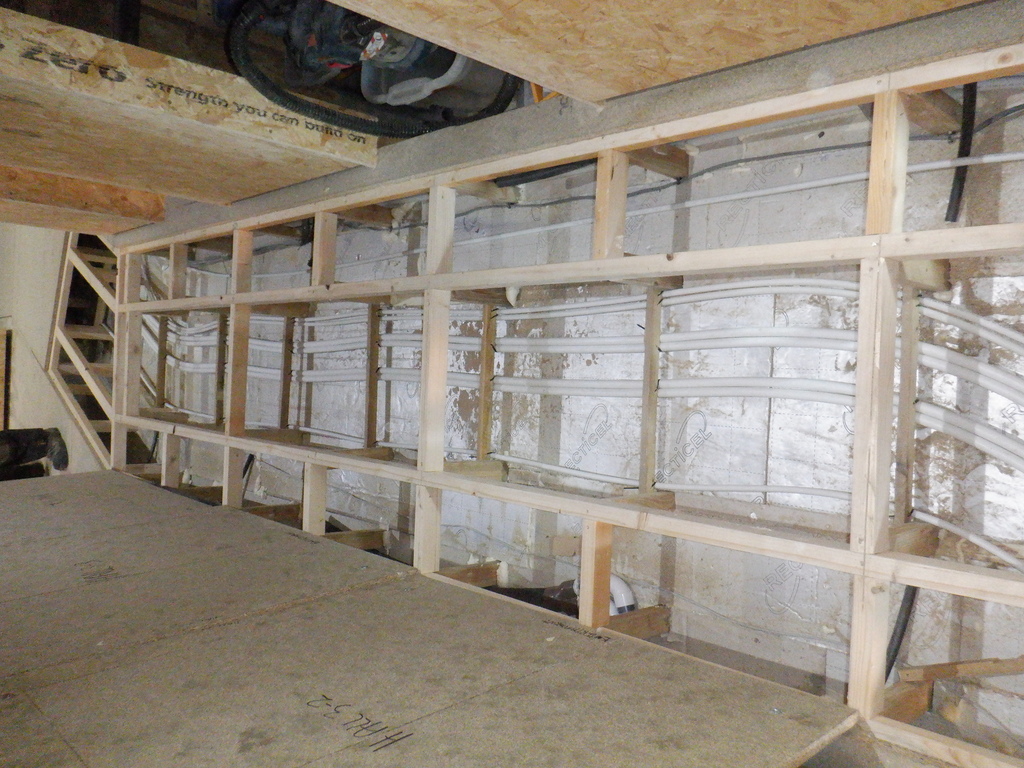
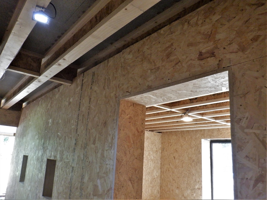
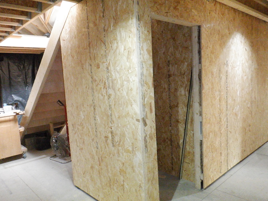
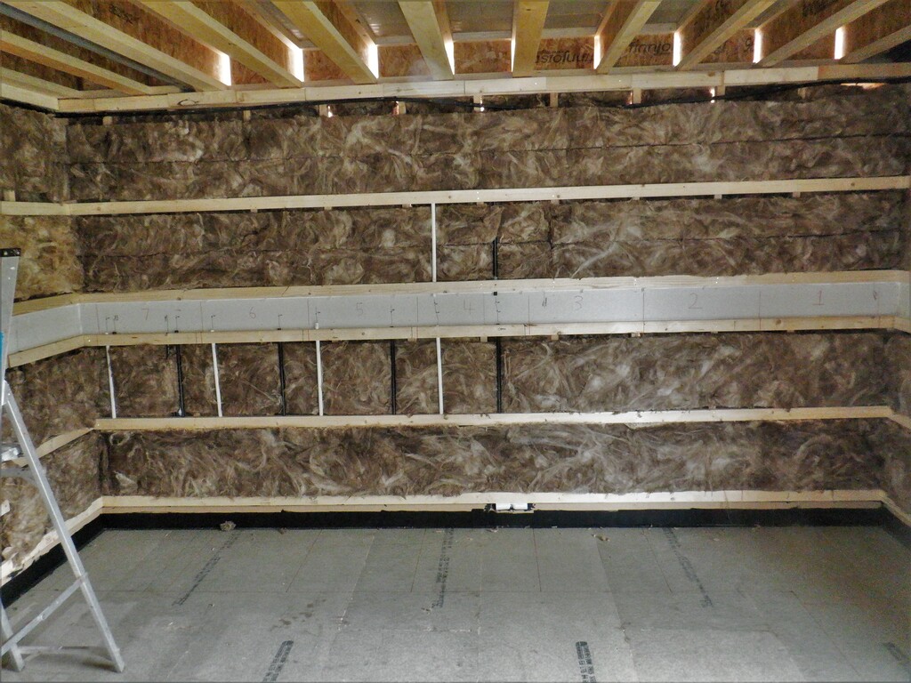
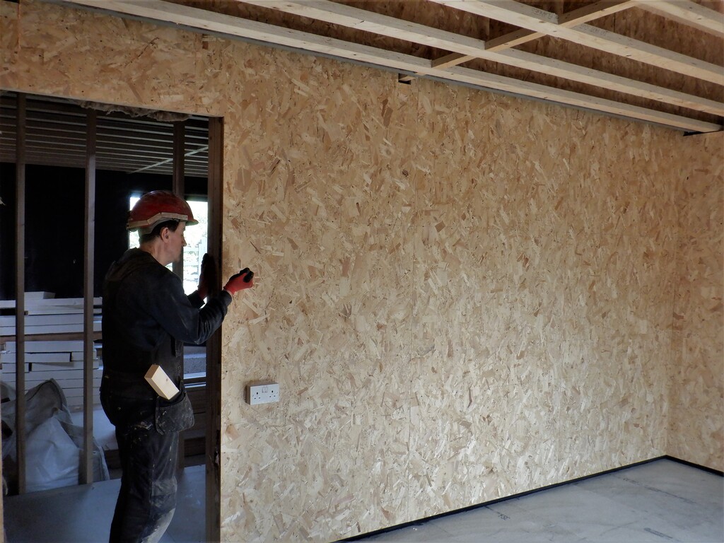
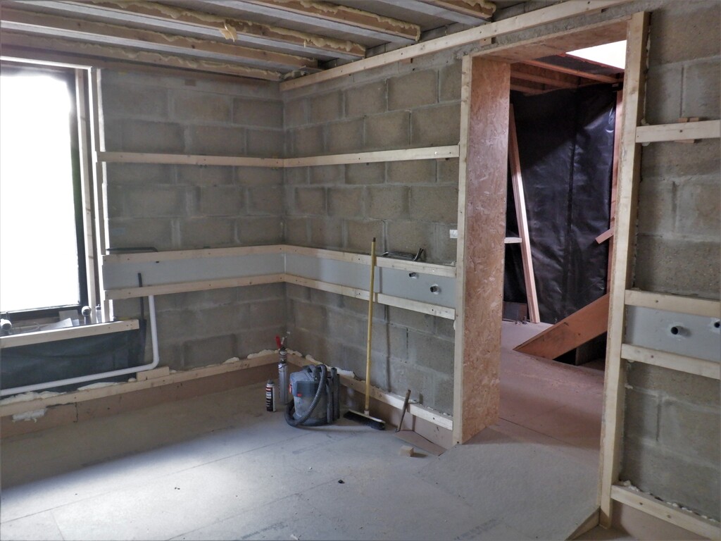
We finally, finishing off this period of work, we encapsulated the doorway in with OSB 18mm pieces of boards, on all three sides, the left and right and also above. We put in the above one in first and glued that piece in up against the concrete lintel and the wooden frame out in the hall, and then measured the two vertical sides. We had to mirror the shape of the floor and ramp so we took a piece of 6mm MDF board and drew a line on it by using a block of wood and a pen to duplicate the slope and flat regions. We did one for each side but it turned out to be identical which was nice to know! We sliced up some OSB sheets into a piece that measures 320mm wide by 2140mm tall and then trimmed the bottom using our template. With some minor slicing a bit off the height, we got them fitted. Next, we put in six pieces of CLS timber pieces into the gap between the wall boards out in the hall and the door frame. This is to make sure that the wall is solid enough to hang our doors on the walls without causing any distortions or warping. The three CLS fillers were glued and screwed into place at the same time when we glued and screwed each of the vertical OSB side pieces.
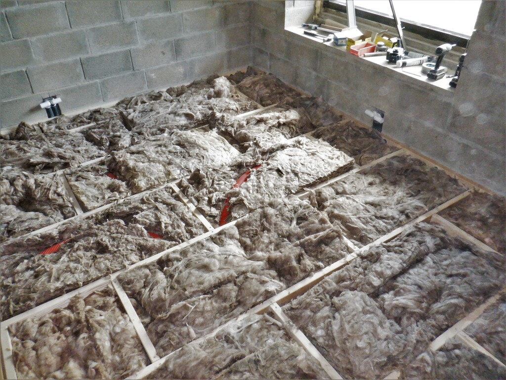
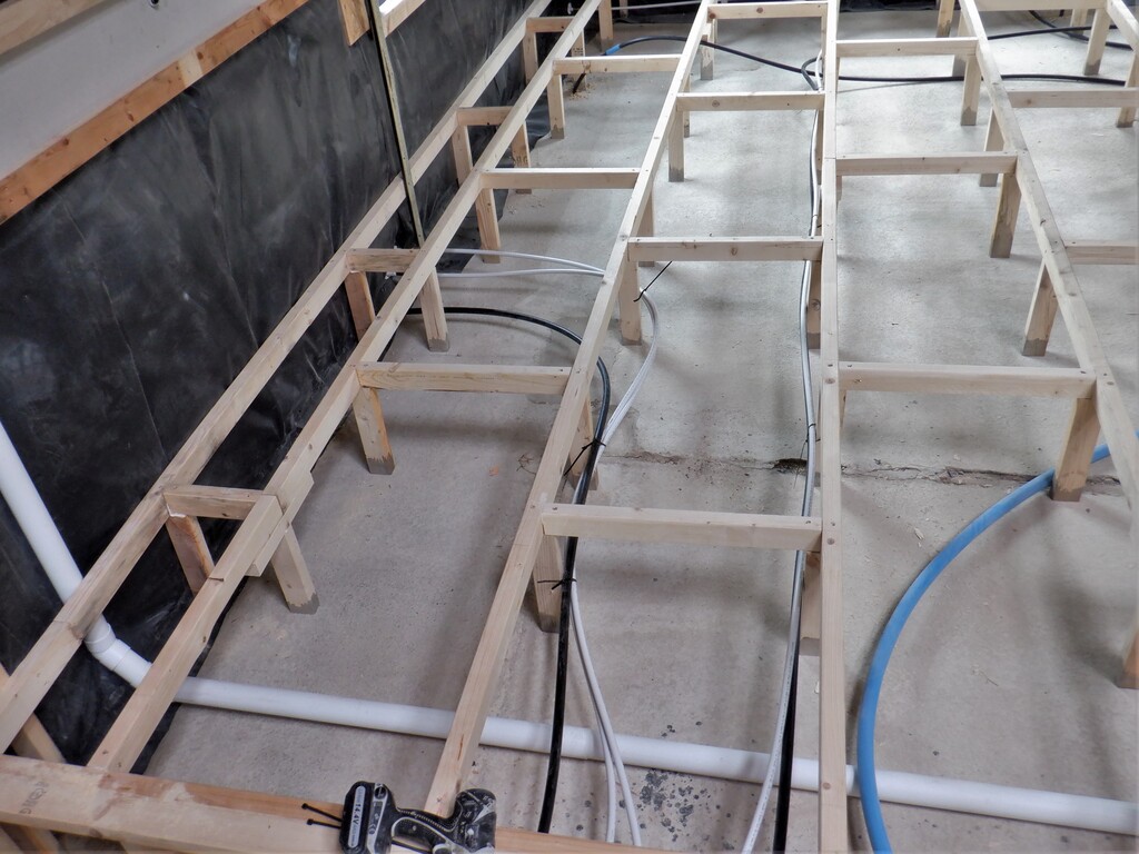
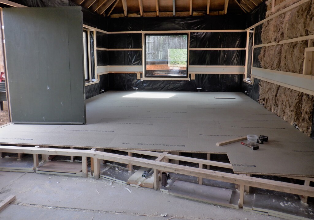
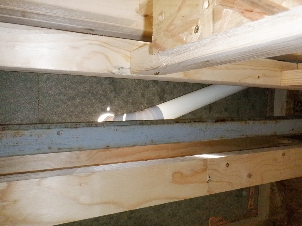
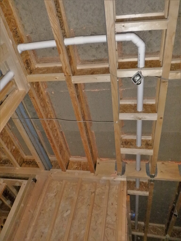
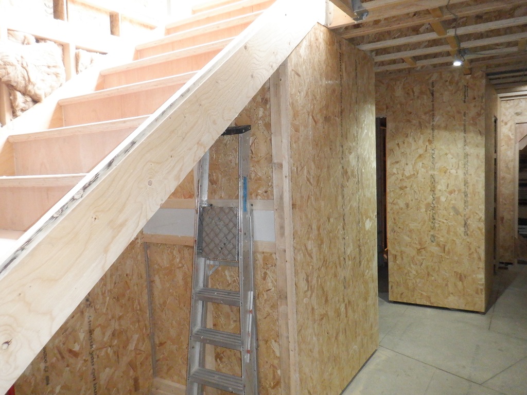
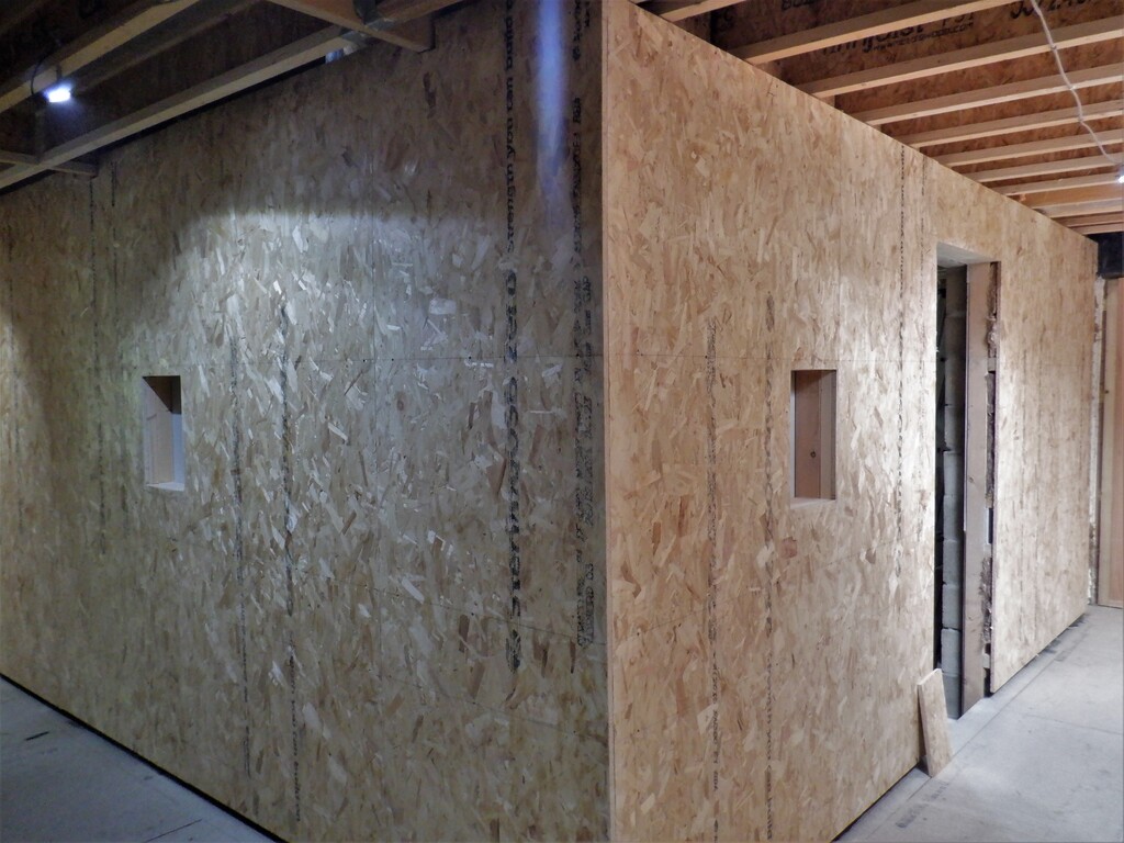
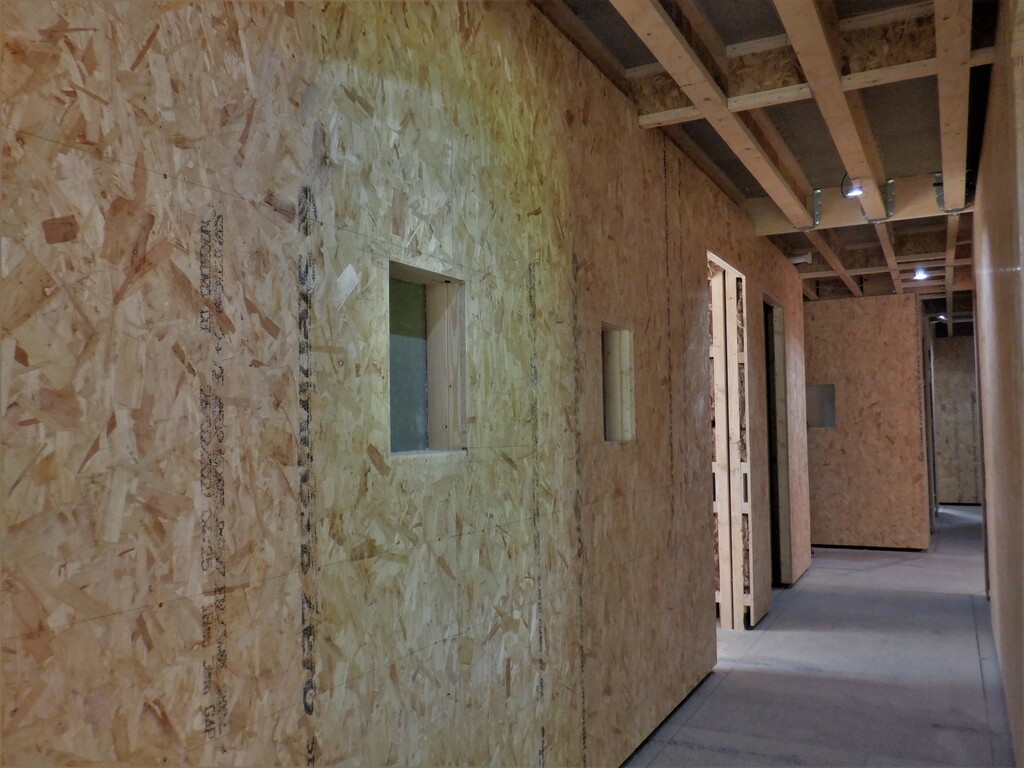
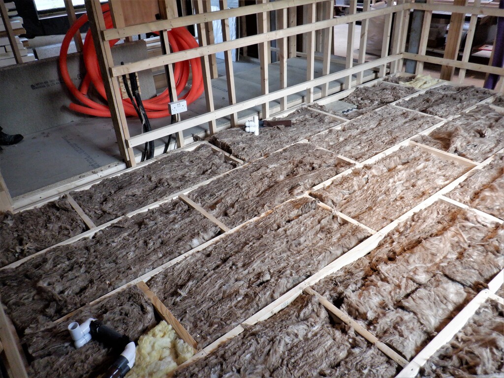
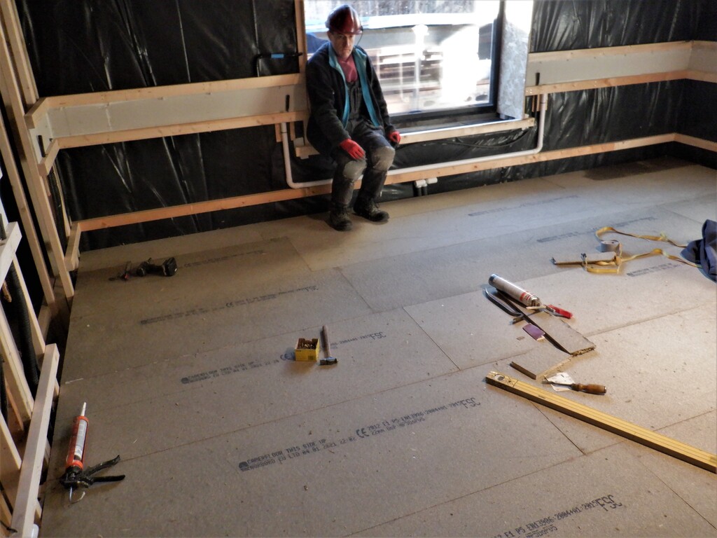
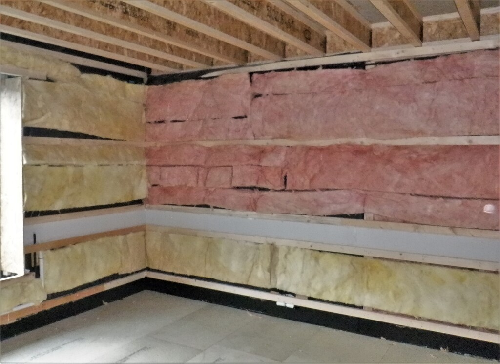
Entertainment-Room-Rails-finished-1
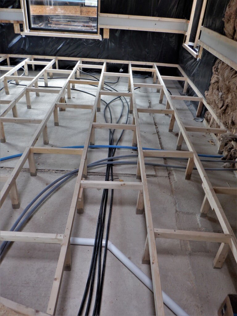
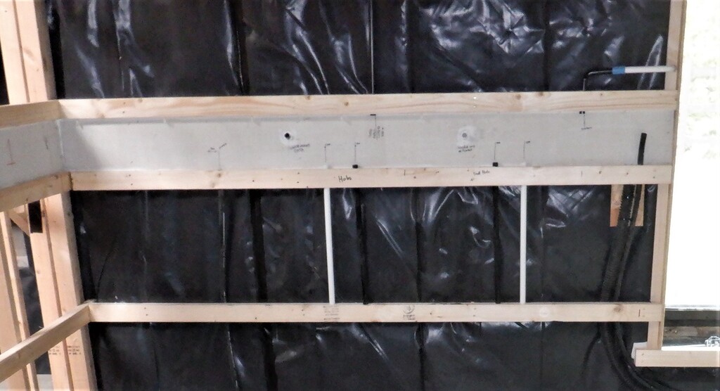
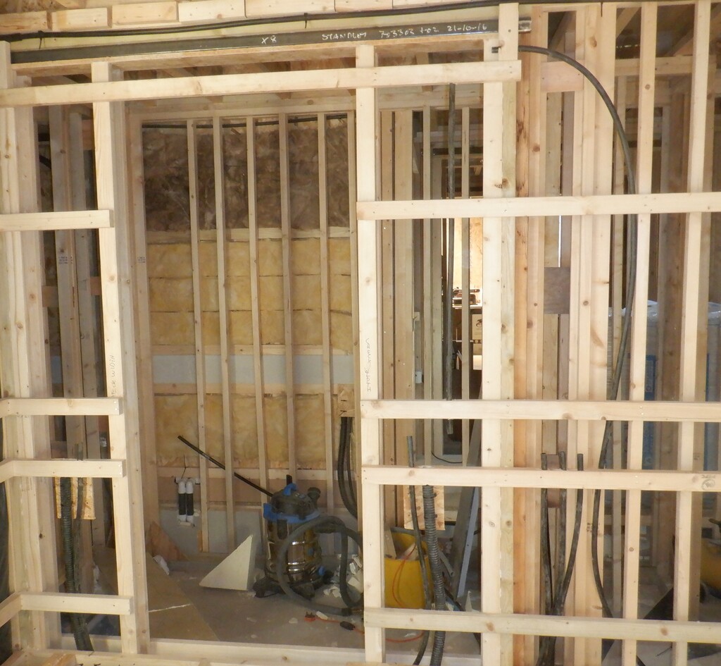
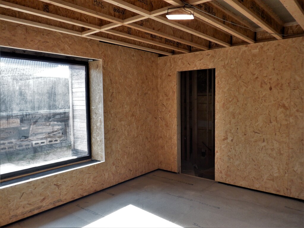
Entertainment-Room-Rails-finished-2
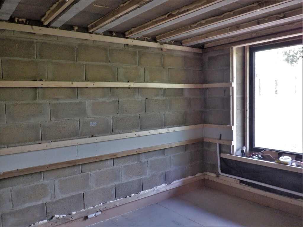
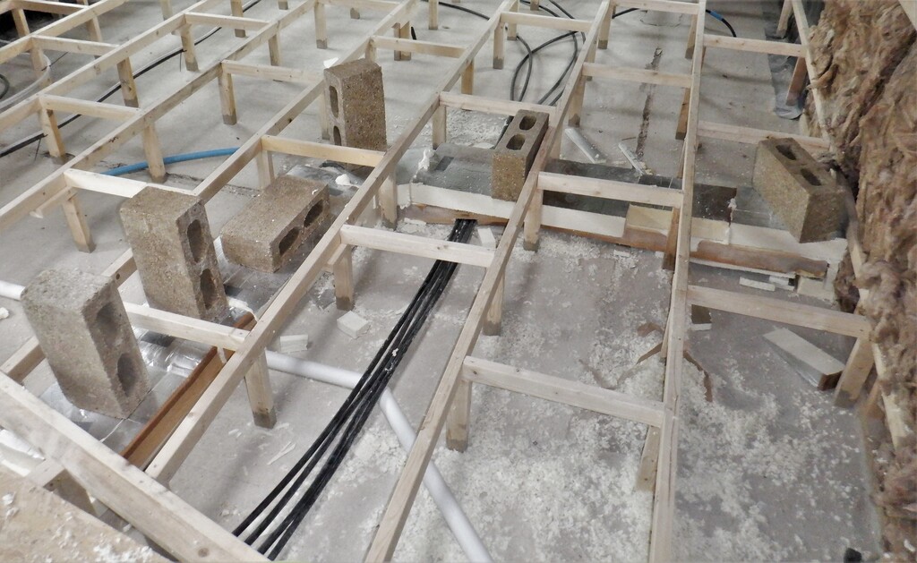
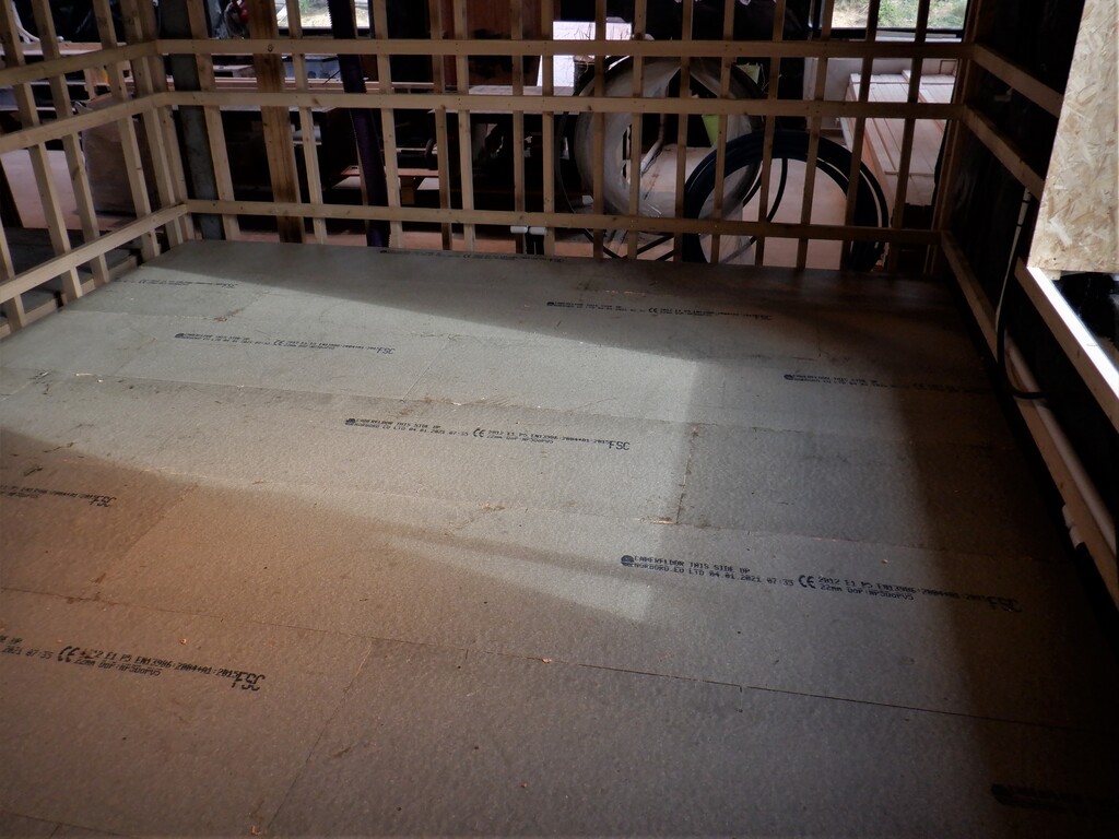
Entertainment-Room-Rails-finished-3
That concludes this period of work on our Entertainment Room, we are not finish of course, but we are moving on to another project next week, something completely different, we are installing our Solar Panels on our roof! All the metal framework and brackets has arrived so we can get that done.