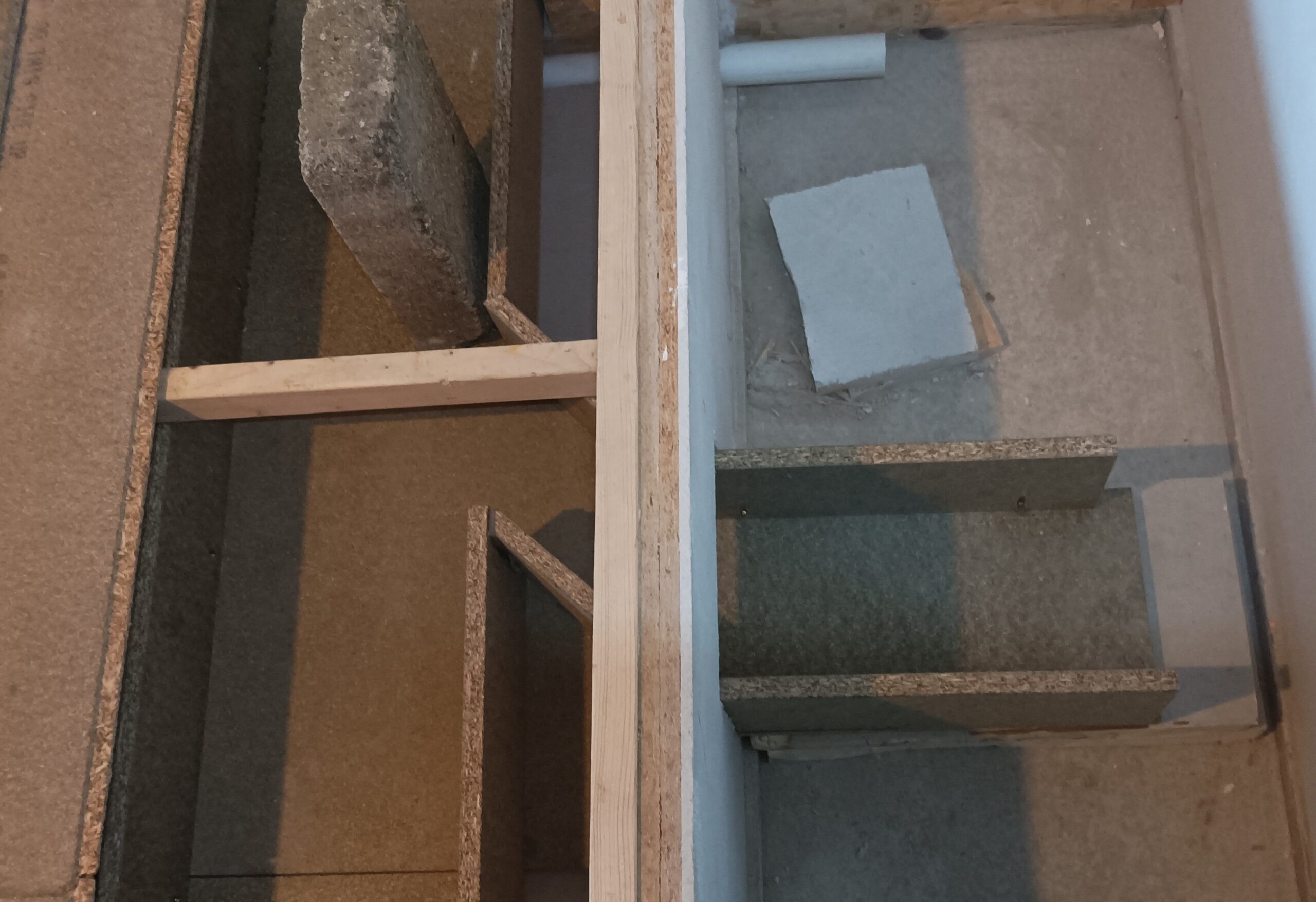
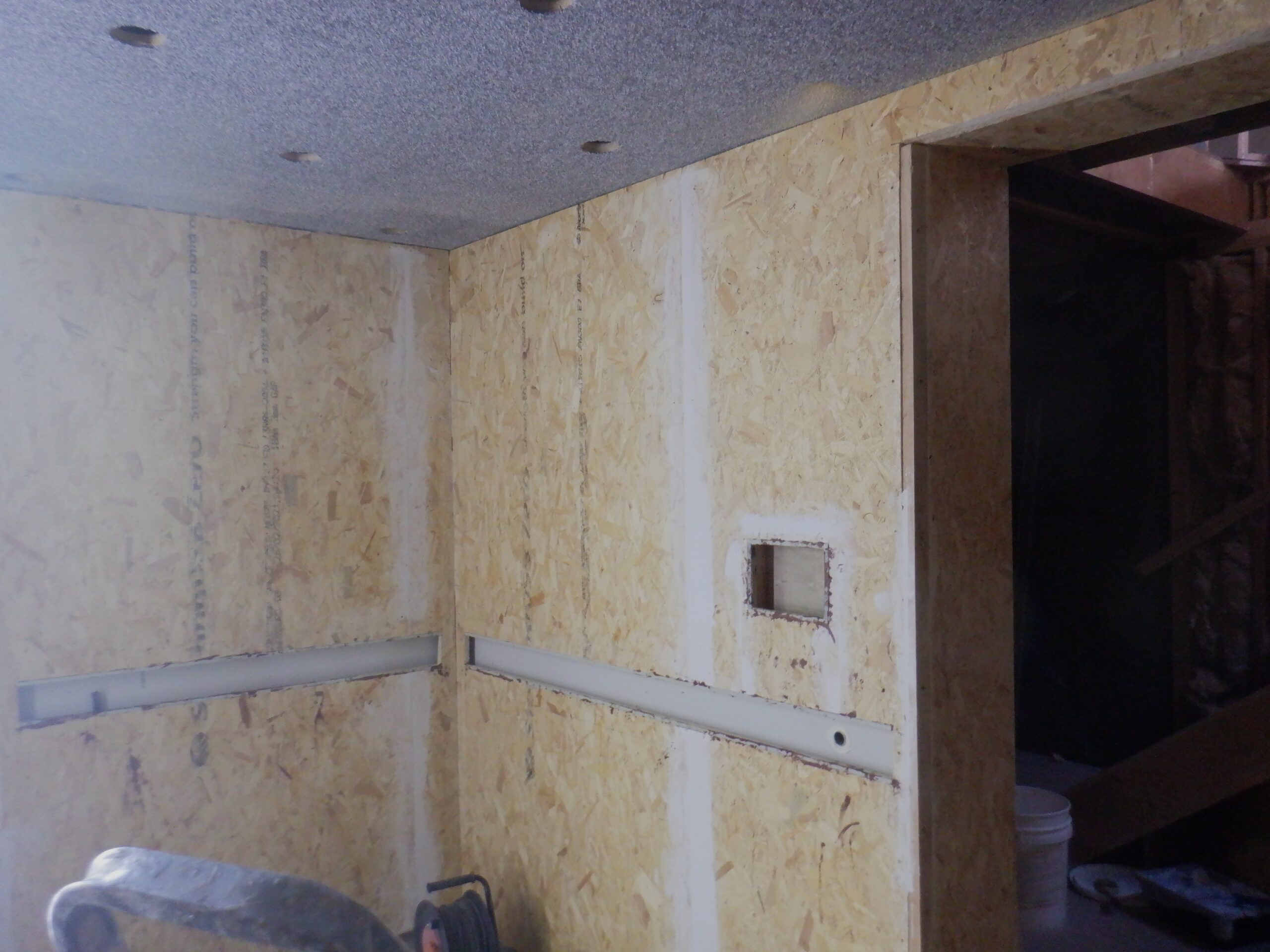
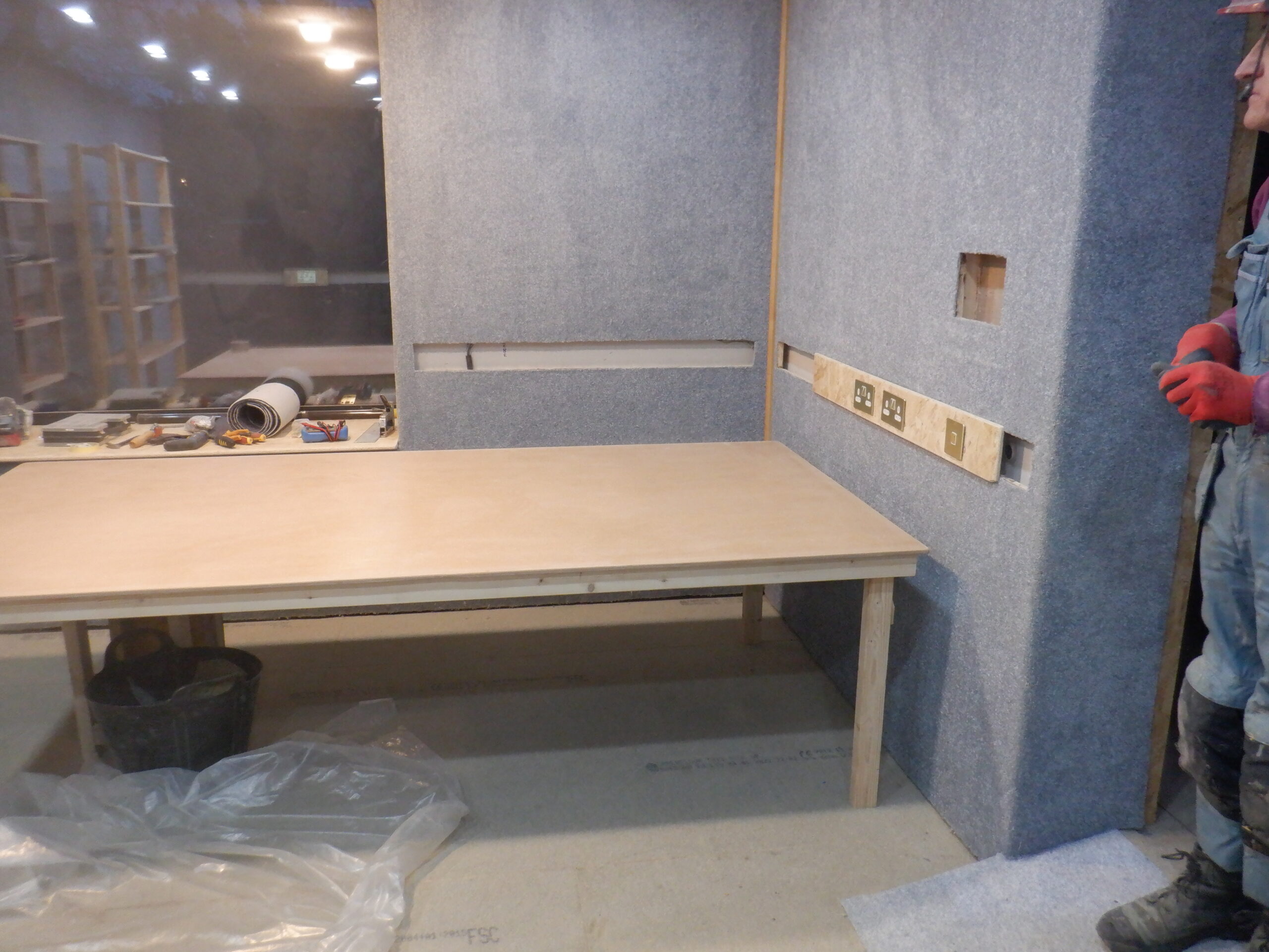
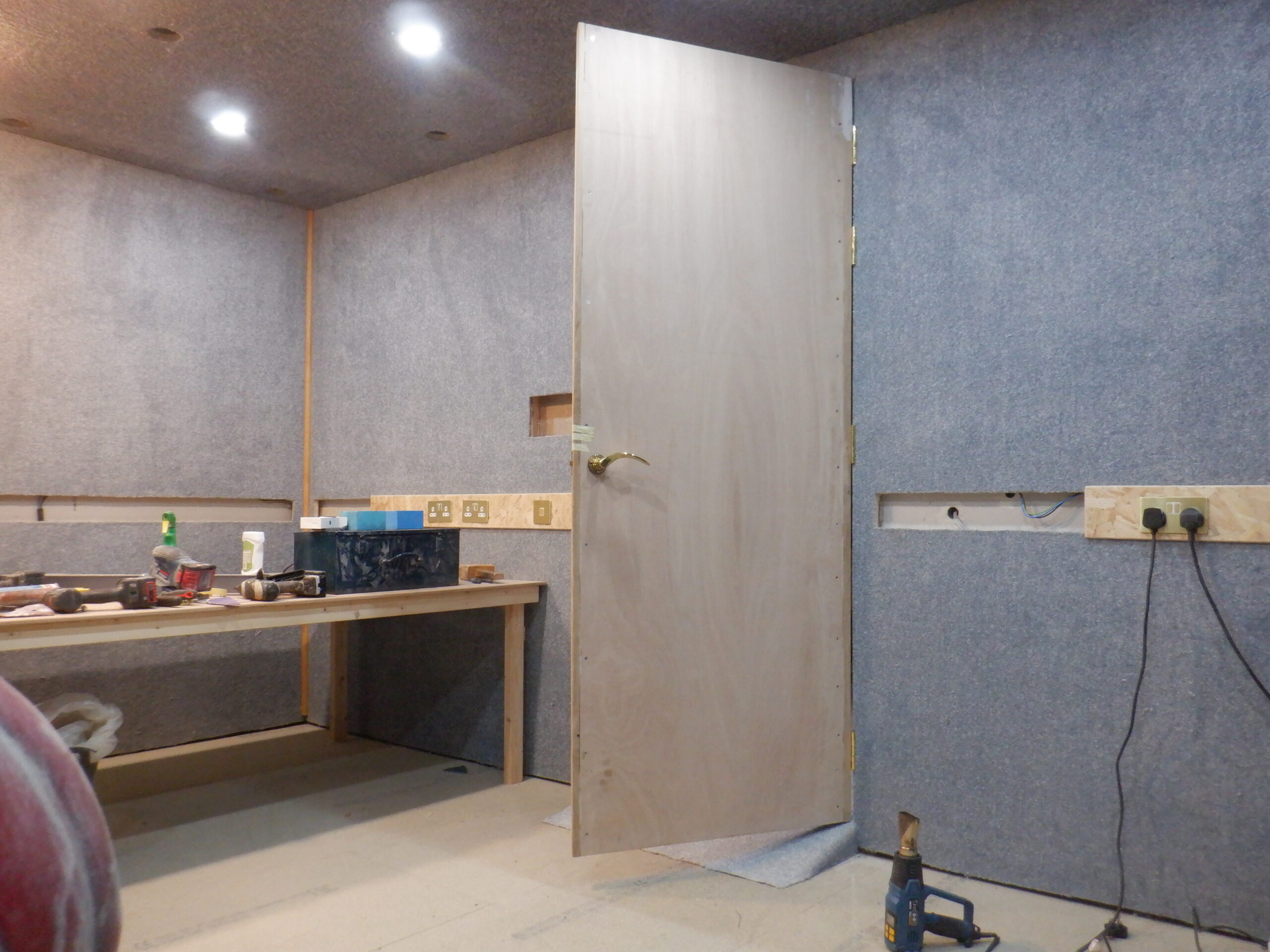
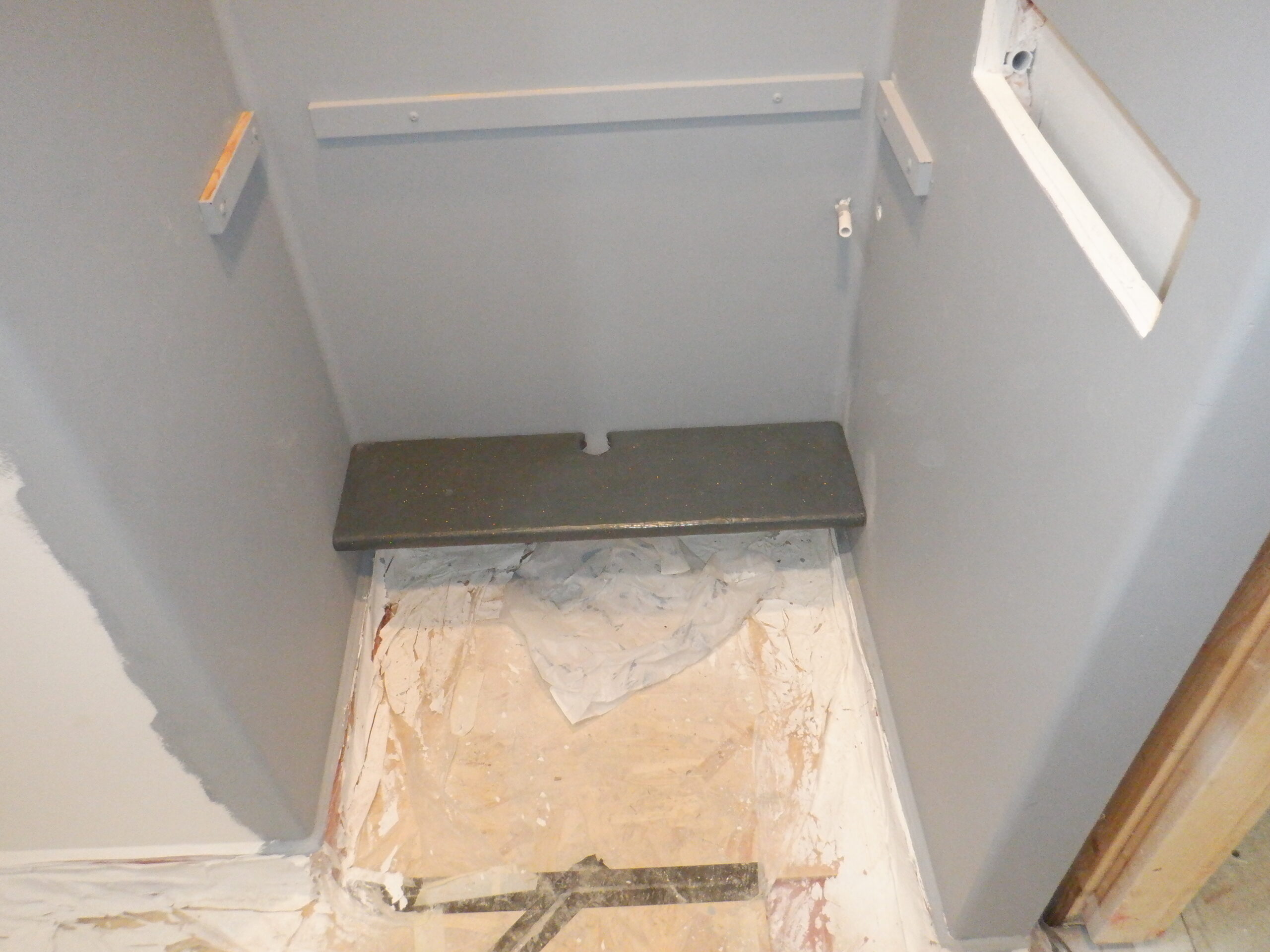
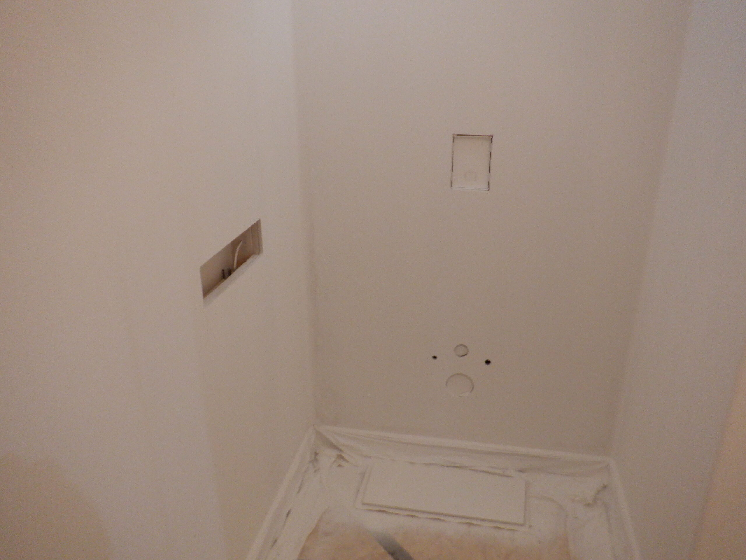
Now that we have finished installing the air ducting and water pipework that are travelling underneath the Cloakroom, we are now tackling the task of building up the inner surfaces of the walls inside the Cloakroom. One of the first jobs, is to put on horizontal utility rails on the door wall, so that we can have a small “control” panel beside the Vanity Unit and the entrance of the door, to provide knobs and buttons, to control the water coming out of the spout in terms of temperature and flow rate. Also, we would have a display to show the temperature when the water is flowing, and default back to showing the time otherwise. There would be a loudspeaker built in so we could have gentle music, or play gentle tones like the hourly chimes etc. finally, there would be a button to make the doors open!! We set this Utility Channel a little bit higher than our normal height, adding another 100mm. We wanted to keep clear of the Vanity Unit so that it is easier to keep the area clean and dry, and keep any water from splashing up to the Oak “control” panel.
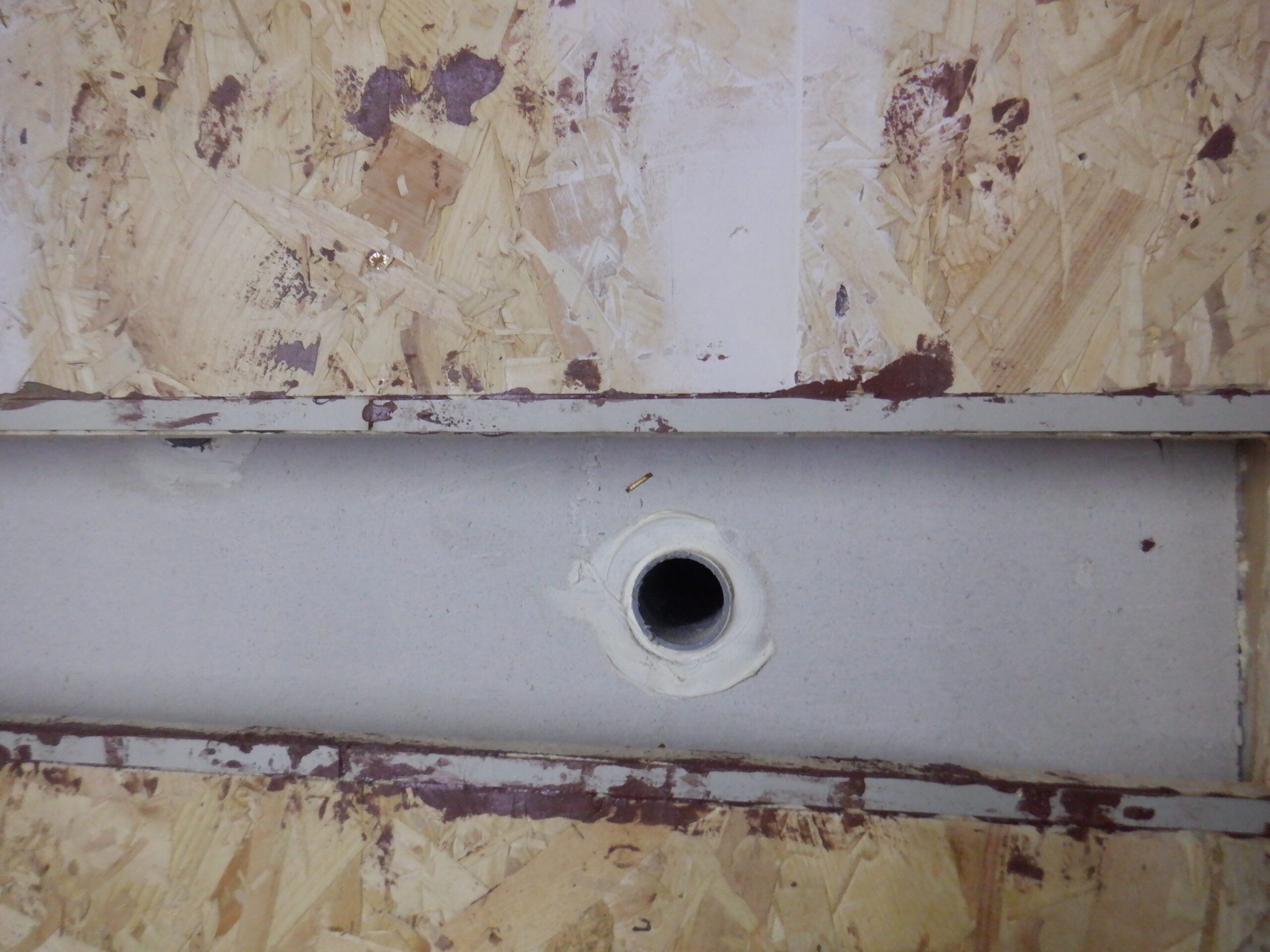
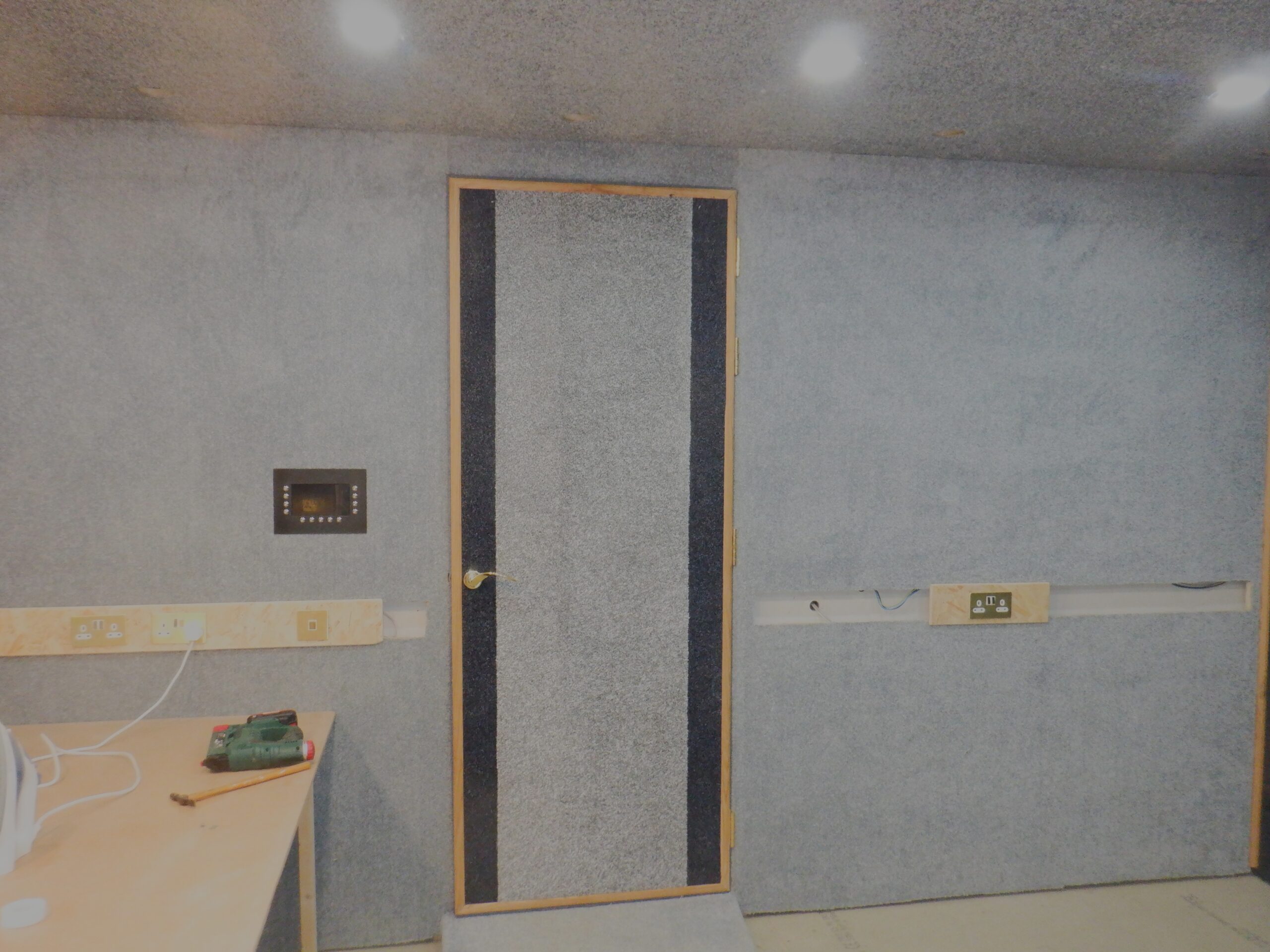
We also put another “control” panel over near where the toilet is situated. We created a niche in between two vertical legs, measuring 350mm wide. The niche is based on the same size and position as the Utility Channel, lifted up that extra 100mm higher. This niche will provide a place where we can put in controls for flushing the toilet, controlling the lighting levels etc. We drilled a hole in the bottom rail for a 20mm pipe, to go down inside the wall, underneath the floor and then back up inside the wall beside the doorway, to the other control box. Then we put in a short pipe connecting this control box to the Hall’s Utility Channel, so we can bring in data and power cables from the outside.
The second control box also have a 20mm pipe put in the side and that travels down the wall and this time, goes across to the toilet and terminates inside the toilet internal framework. This will provide the means of adding extra features to the toilet, like having a heated seat, or perhaps have sensors to detect when the seat has been lifted up. A third hole was also drilled in the side of that control box, a smaller hole, to take a small 6mm plastic pipe, which also goes down the wall and across to the toilet as well, which will join with the existing bellows that causes the flush action to occur.
We have measured exactly where these control boxes are, so when the wall boards have been installed, we can cut out the small segment of the wall, to to replace it with a piece of oak which will have the buttons and bits and pieces on them.
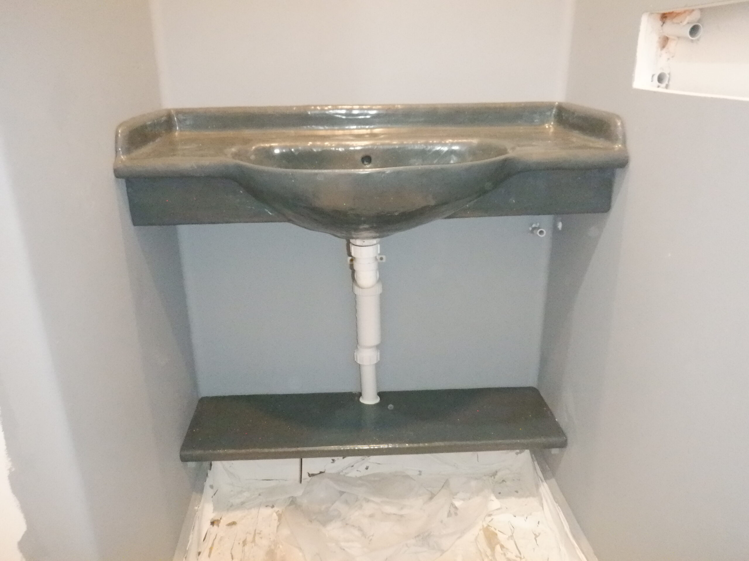
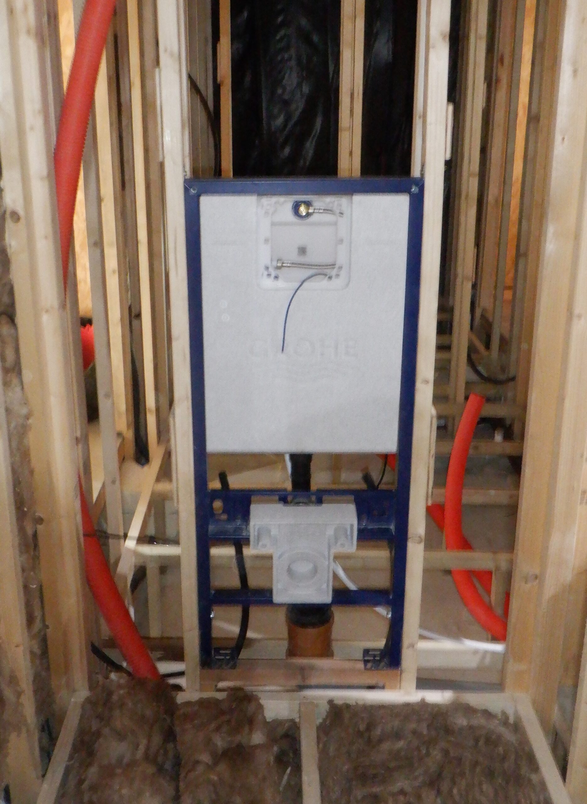
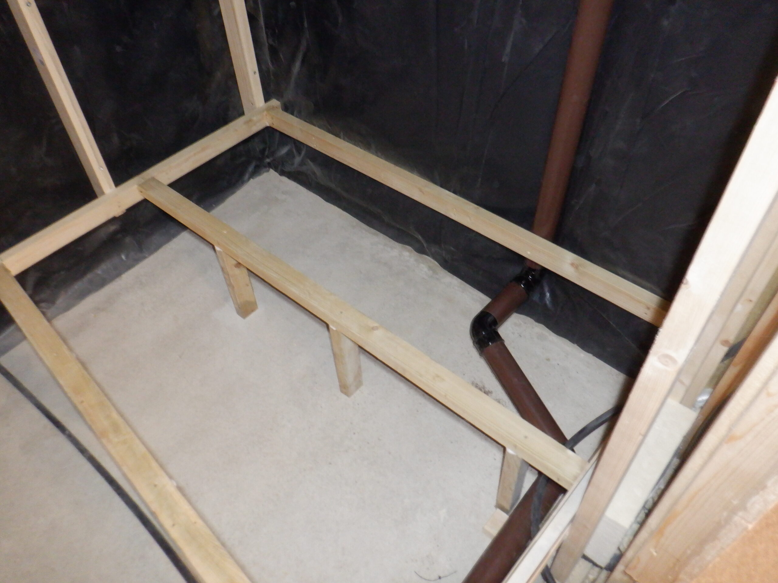
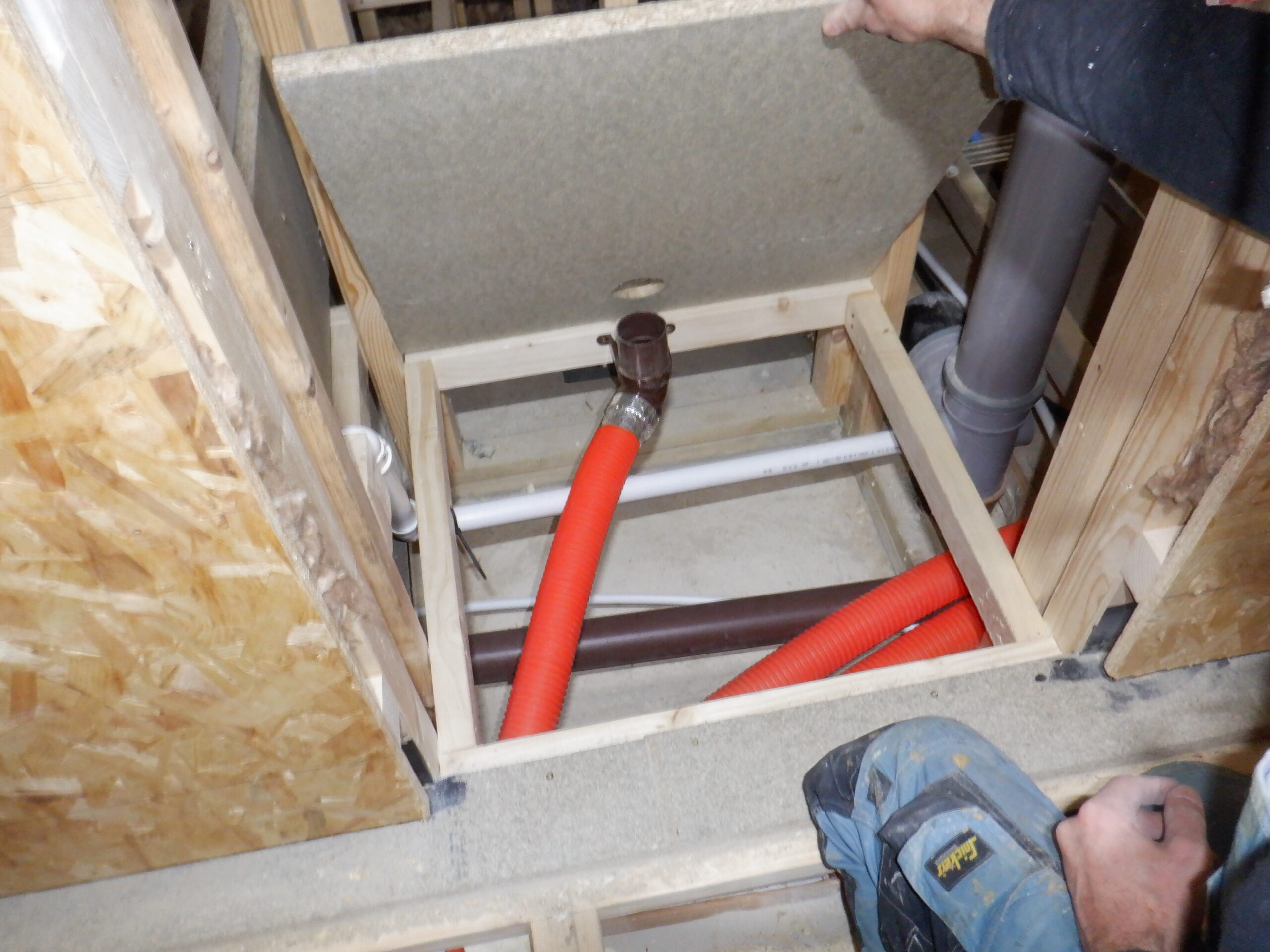
We then turned to the task of installing the toilet framework and cistern into the body of the wall. We have gone for wall mounted toilets so it makes it much easier to keep the floor nice and clean, but also, hides away the cistern itself too. There will be just a small square access removable panel, so one could service the cistern, or even replace the filling mechanism etc. Everything is hidden inside the wall itself and will only show a small push button to flush the loo. We decided to take the opportunity to raise the toilet up higher than typical toilet bowls are, because it is sensible as we are all getting older. This metal framework provides a method of sliding up and down, to control the overall height of the ceramic bowl and we went for an additional 100mm higher, to make it come up to around 500mm off the floor, instead of the usual 400mm. Having done that, we then could measured the position of the large waste soil pipe and cut a piece to go horizontally from the stack, which then turns 90degrees upwards to join onto the elbow connecting pipe that comes from the ceramic bowl itself. Now, that we got this major pipework in place, we then could secure the framework into place using four coach hex-headed screws, two at the top and a further two at the bottom. That is it!

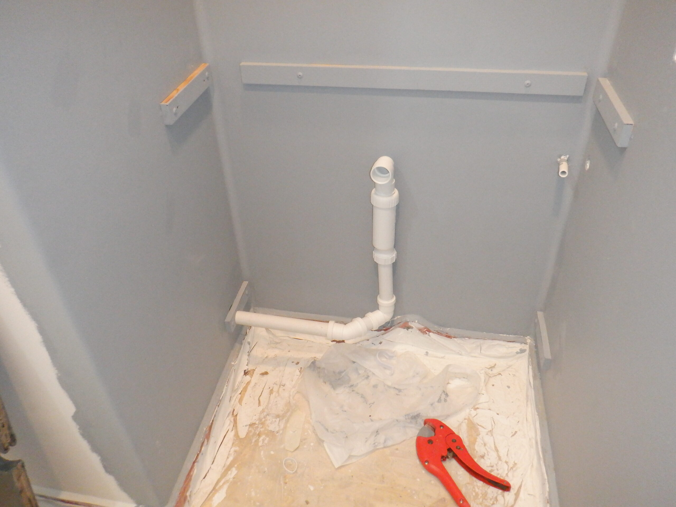
Cloakroom WC Frame
We then connected the cold water 15mm pipe to the back of the unit, using a tank connector fitting to a copper pipe, which we soldered on a short piece of copper pipe and then bolted on a right angle bend which then had the plastic 15mm pipe inserted in and tightened down.
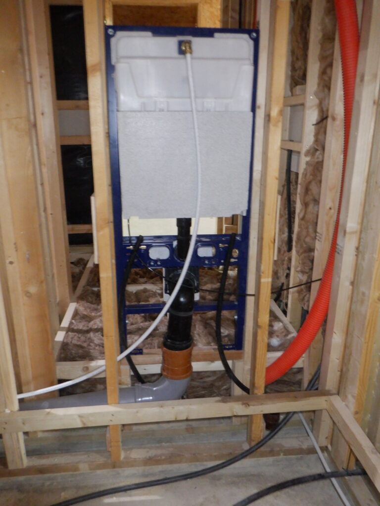
Back of Cloakroom WC Frame 2
We put in a couple of 20mm pipes, one of them coming from Bedroom One’s Utility Channel, to provide mains electricity if we ever needed that and the second pipe, coming across from the small control box already mentioned above.
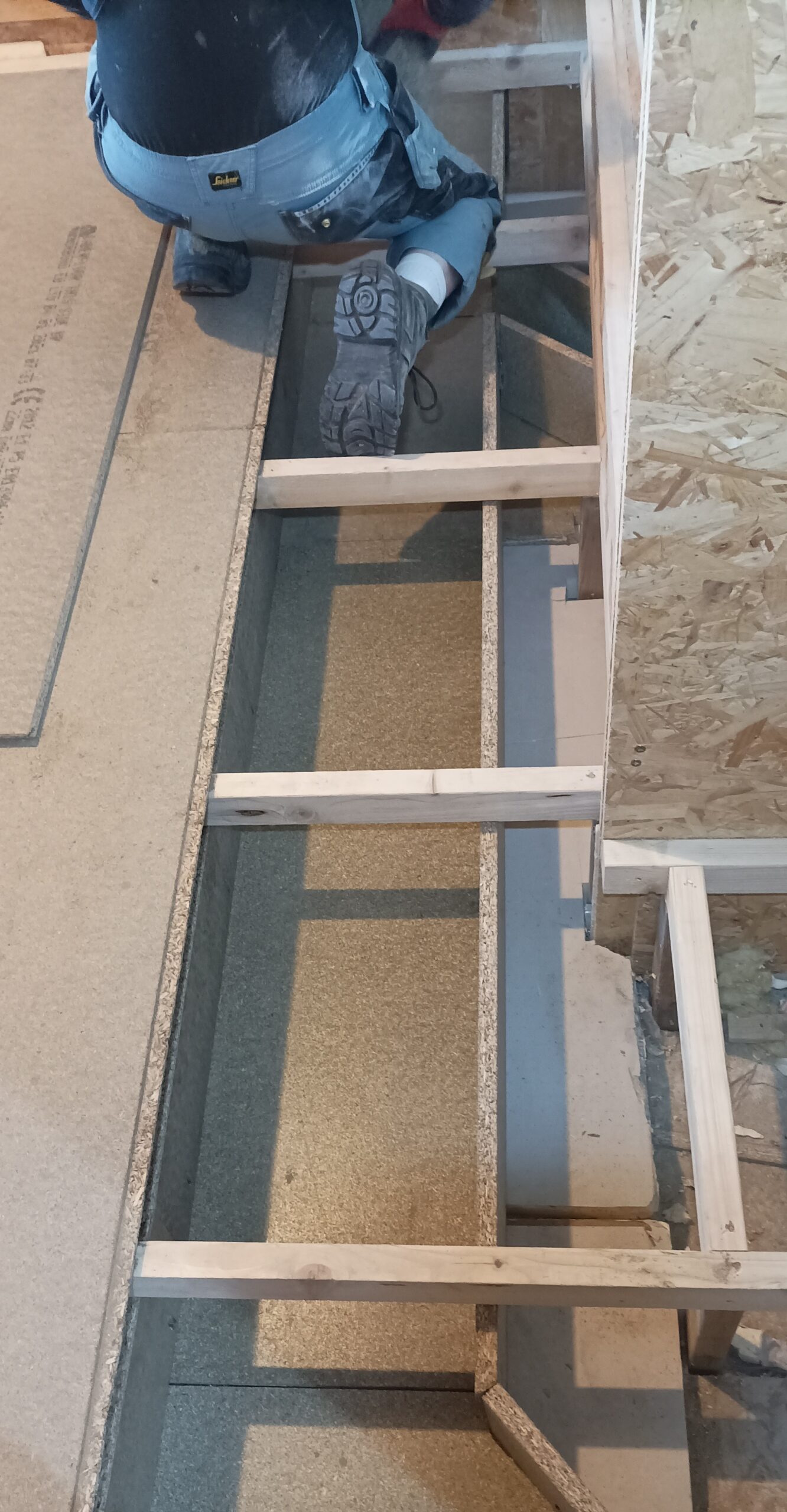
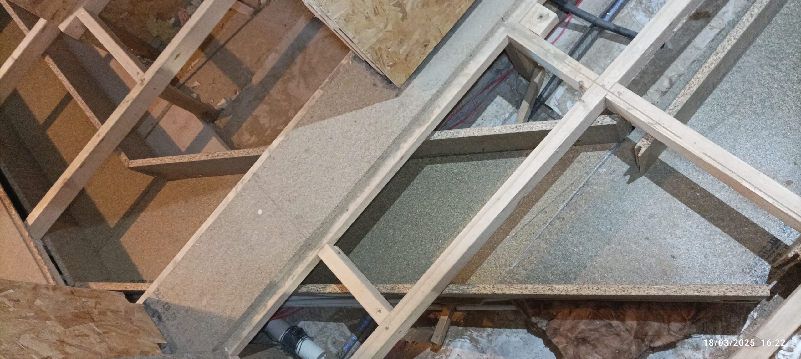
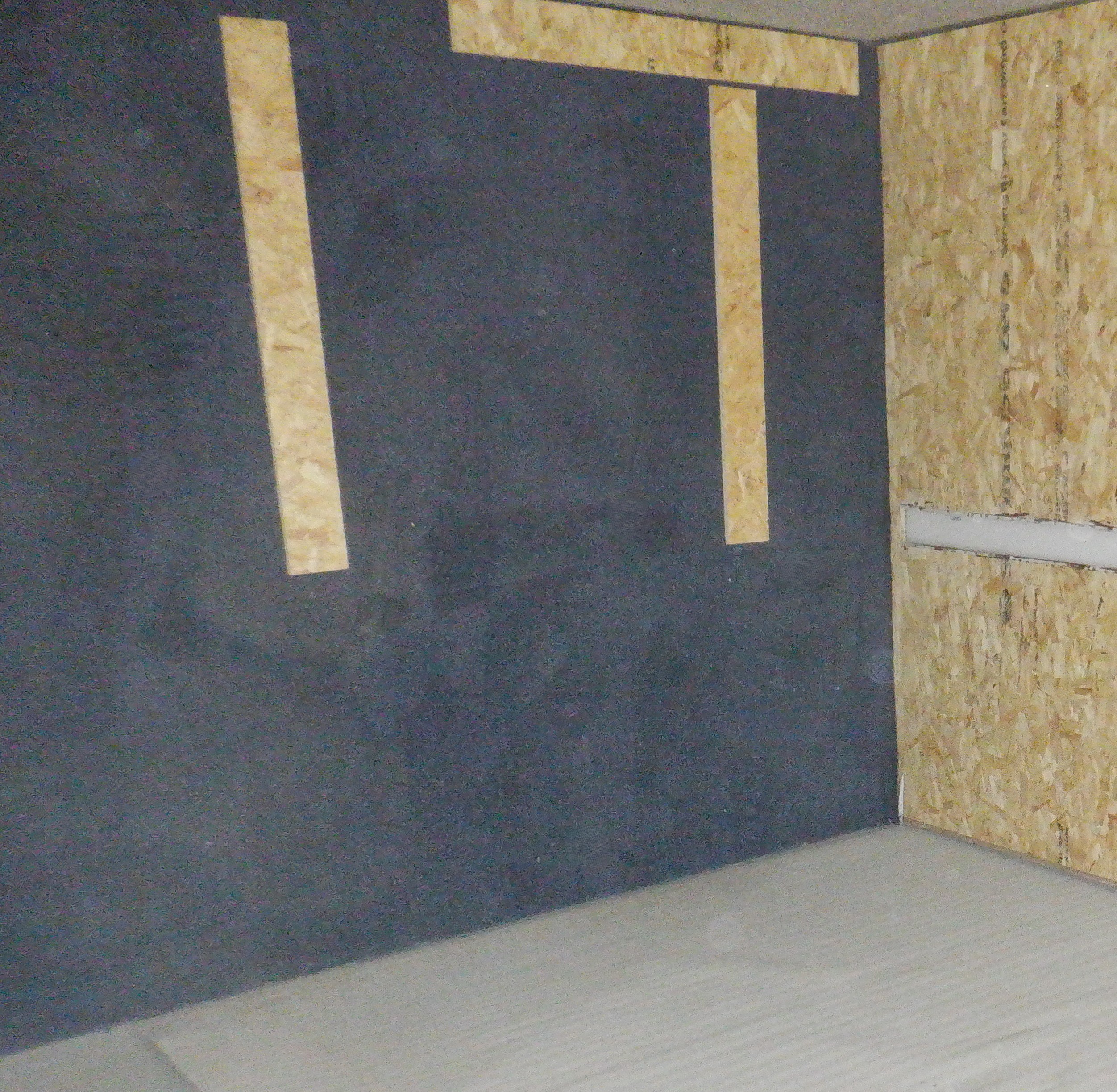
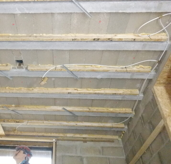
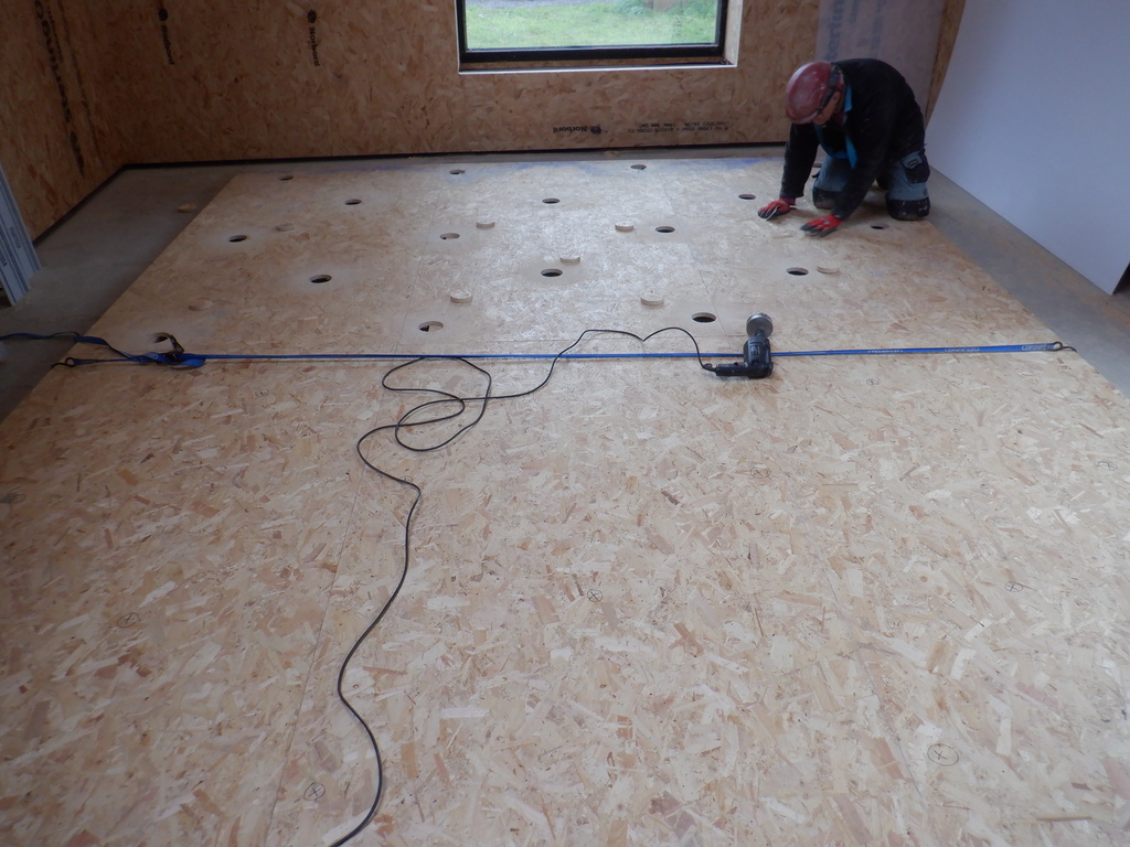
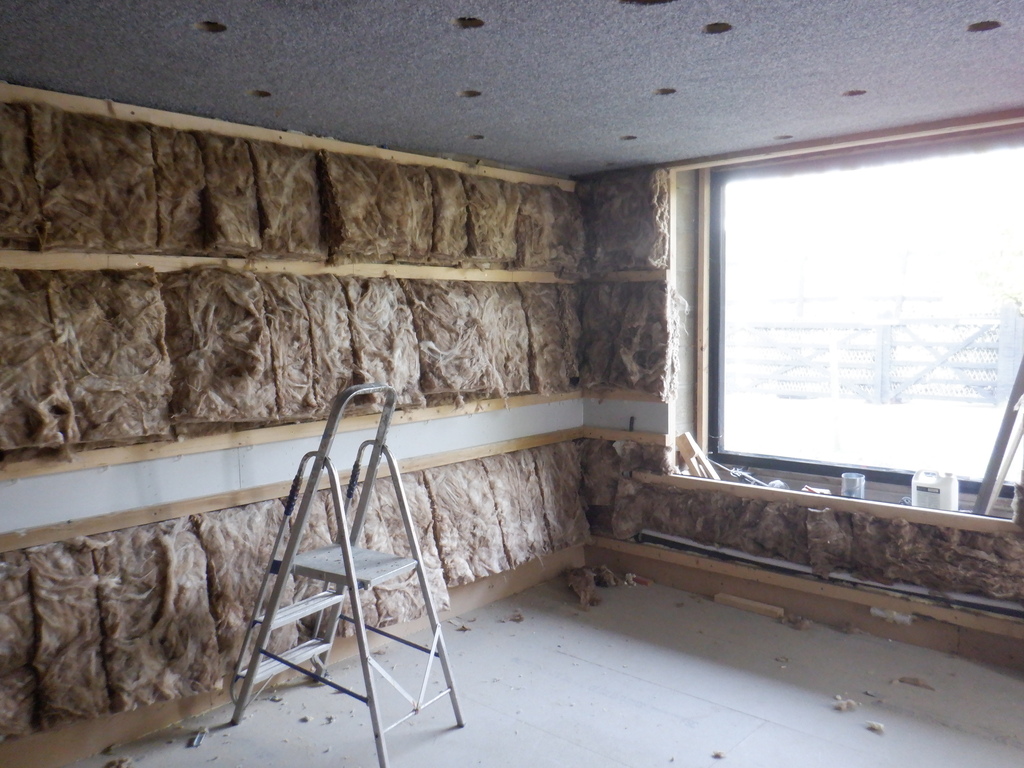
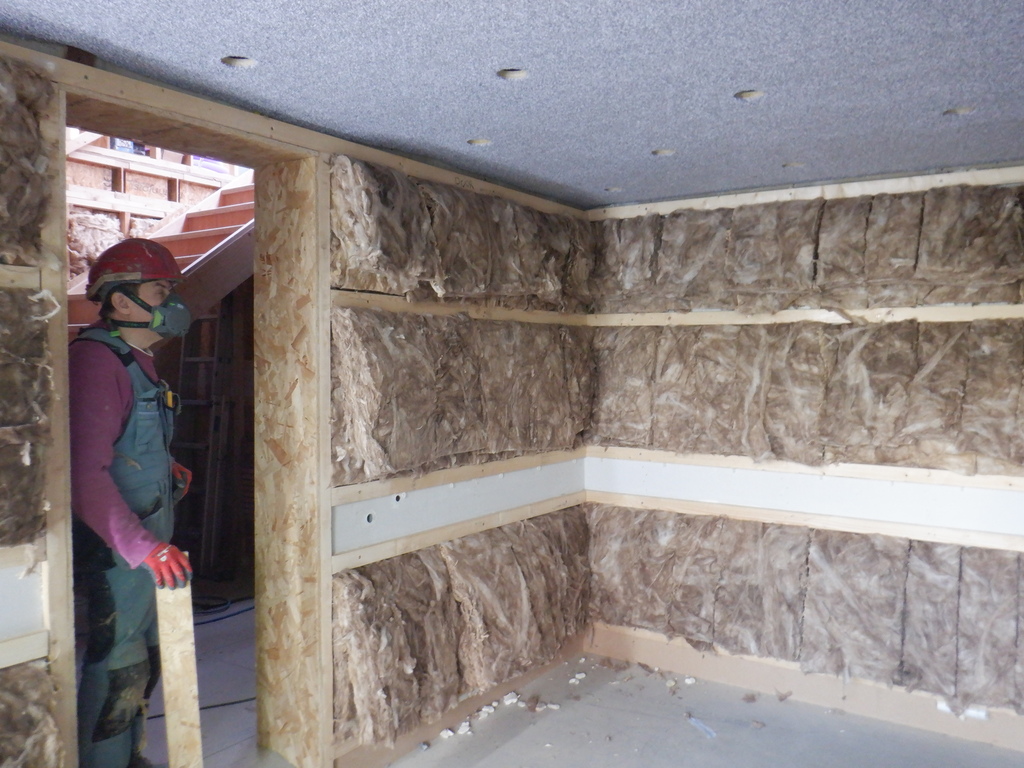
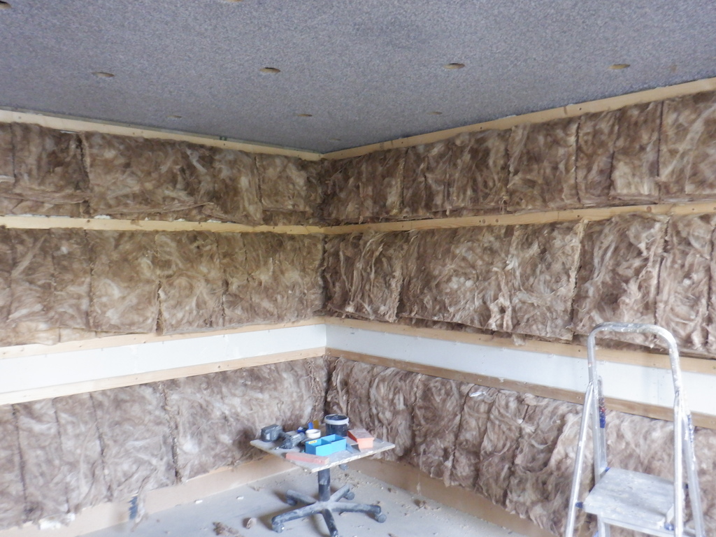
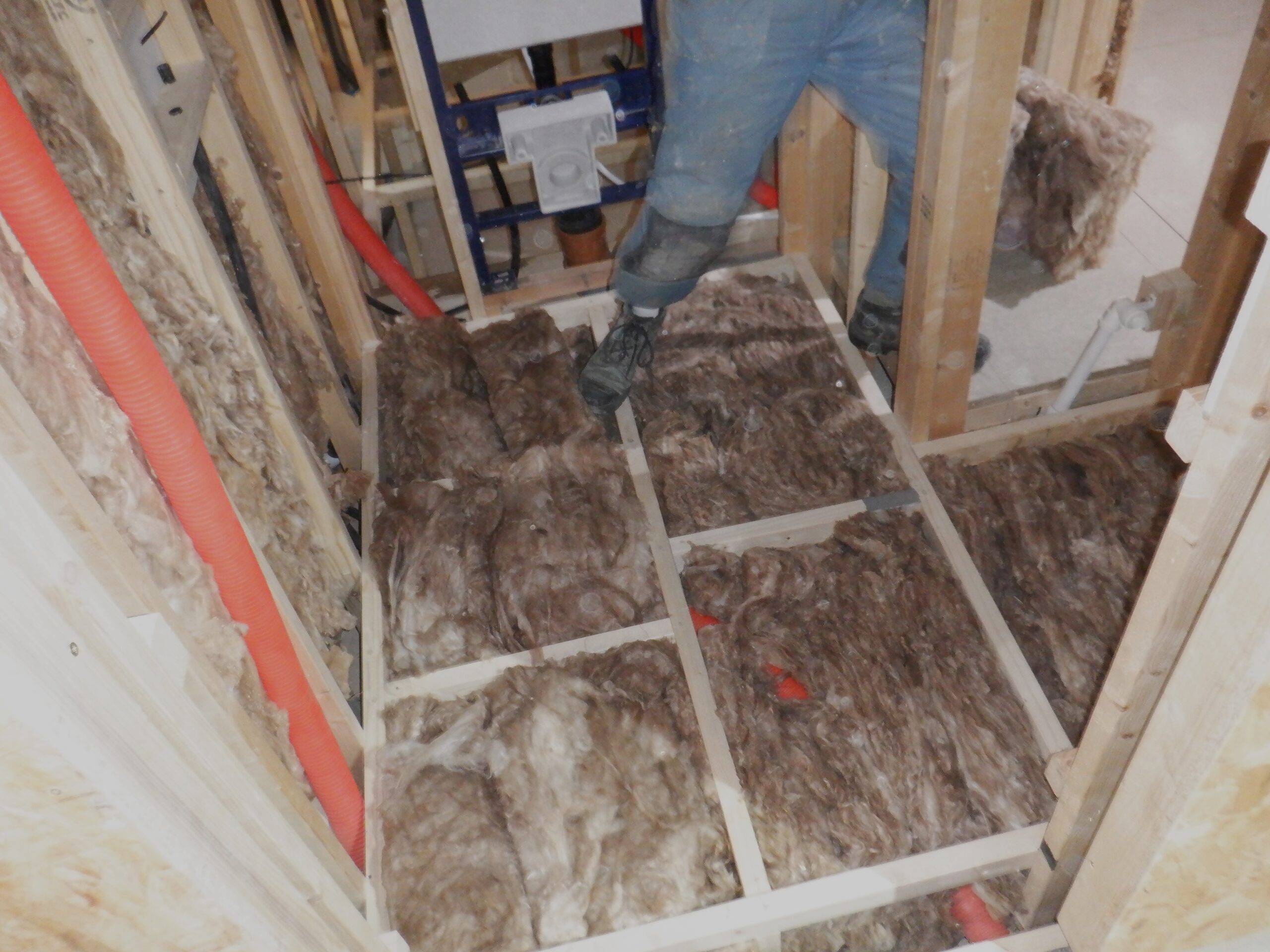
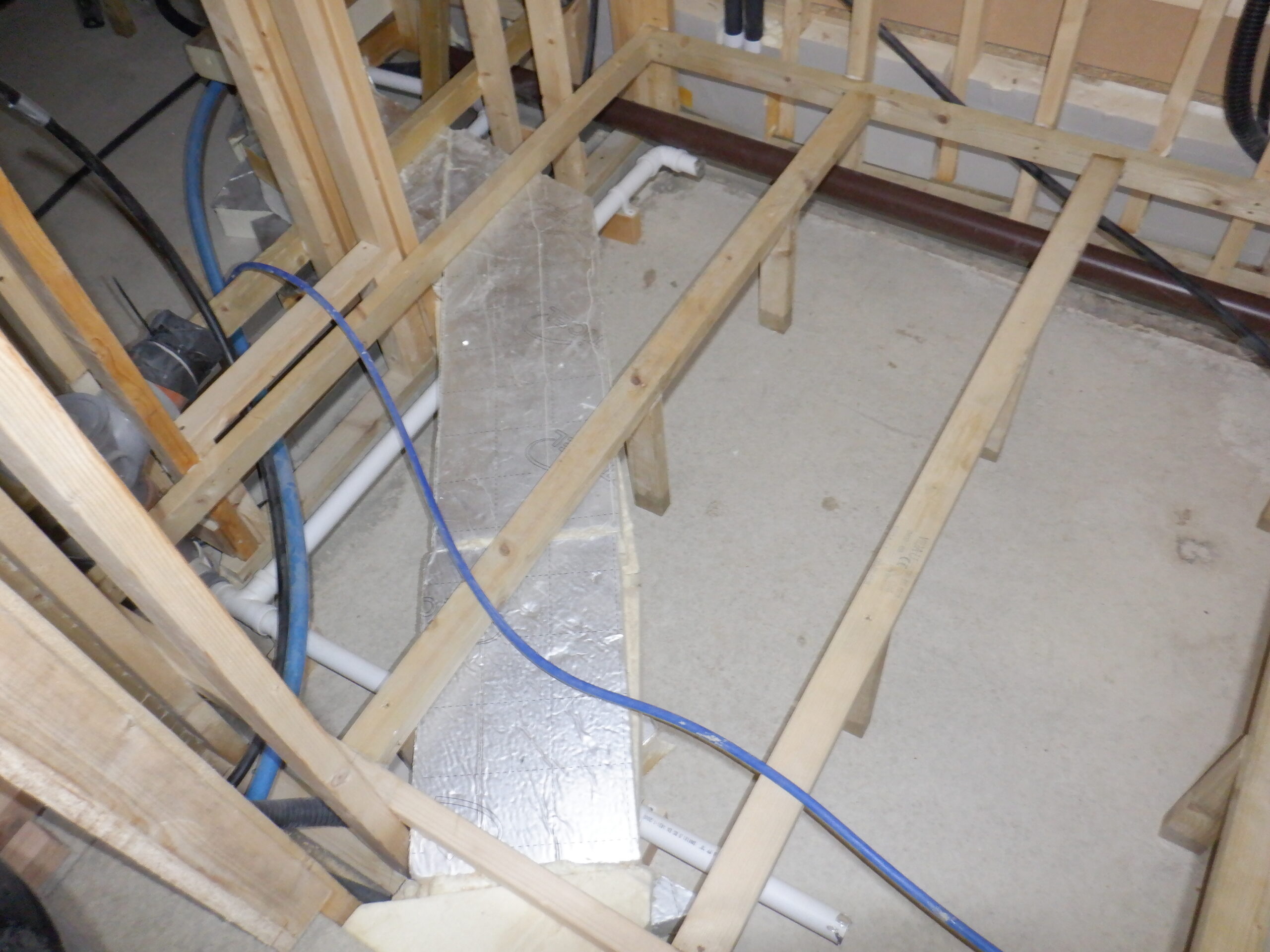
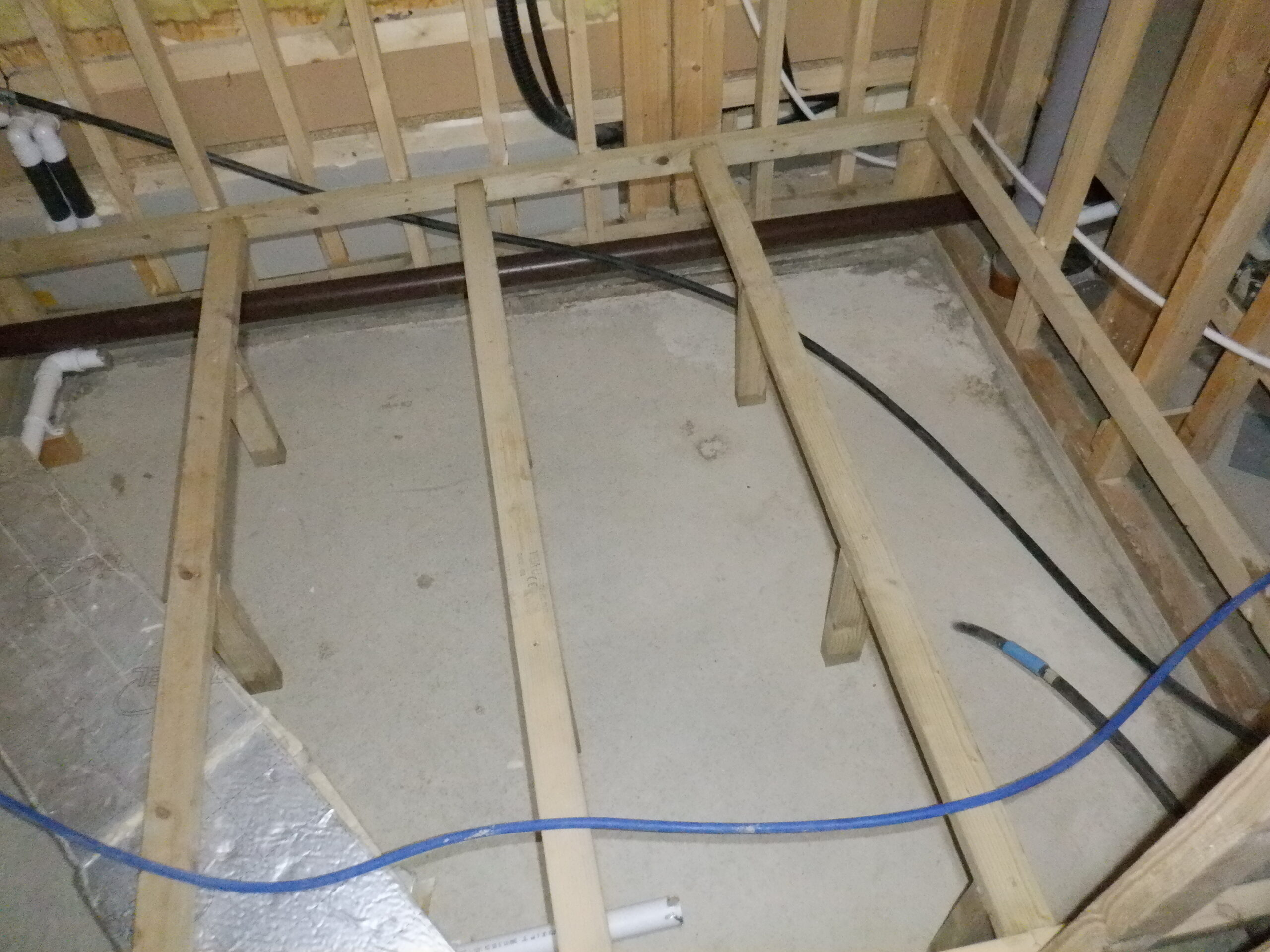
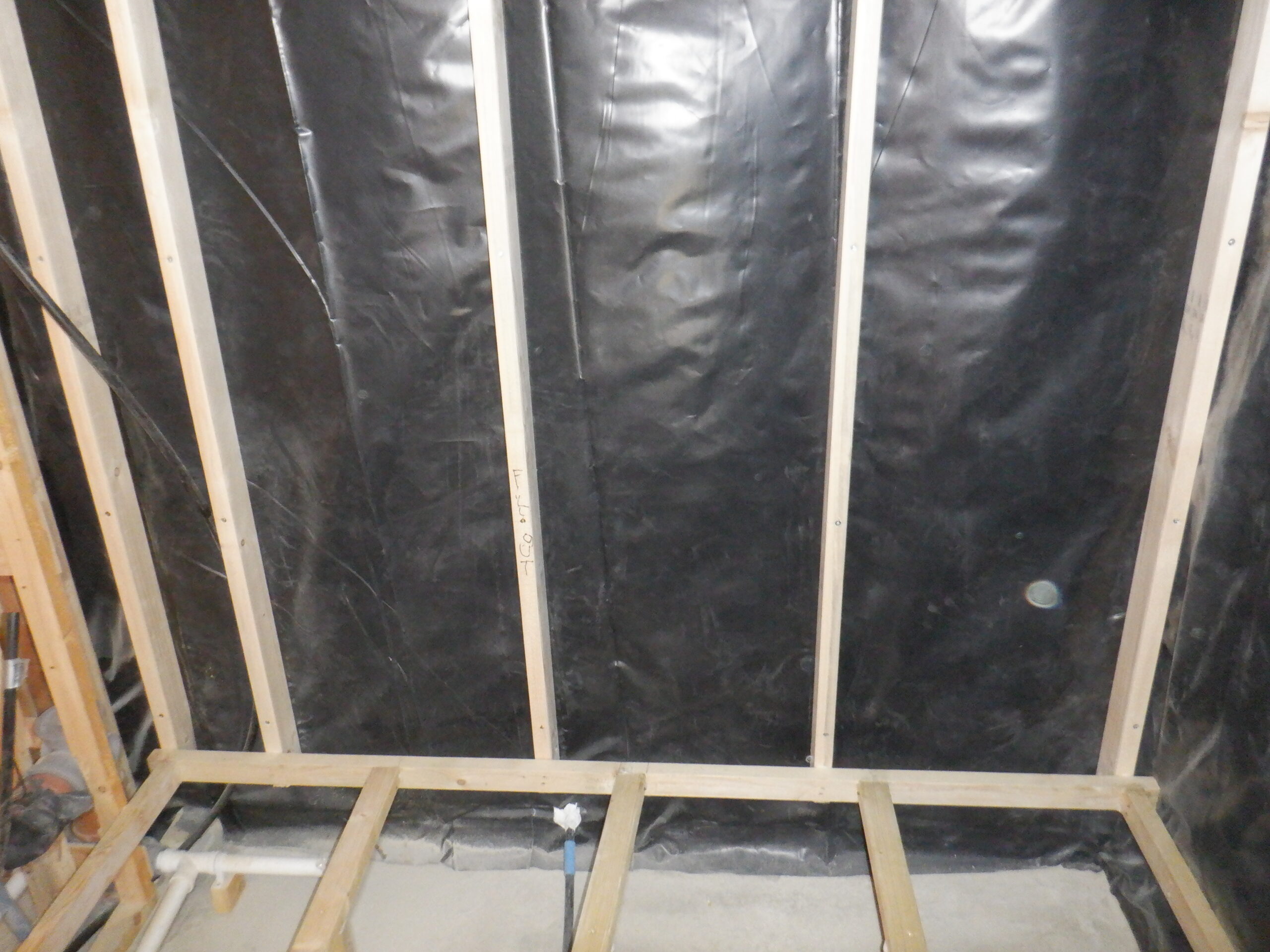
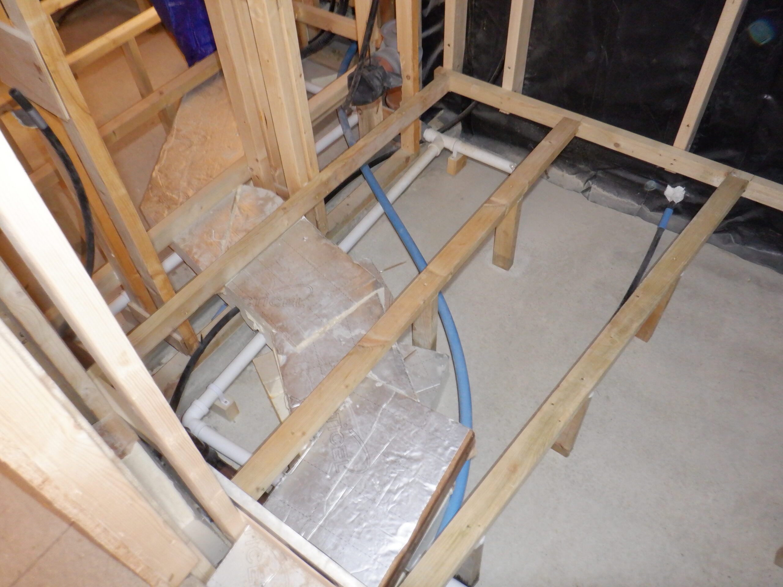
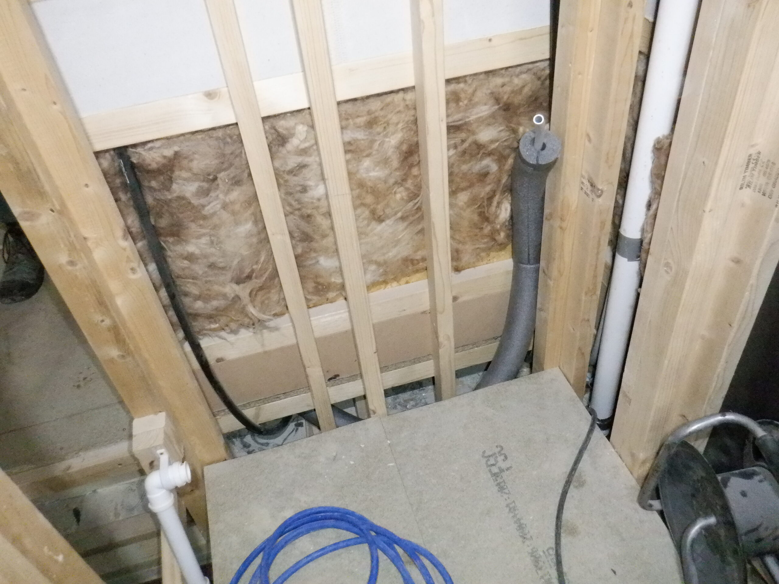
That concludes all the conduits and pipes going from here to there, including going under the floor as well, so we could get on with the next task. This is where we put in lots of glass wool pieces in that large space under the flooring, like we have been doing in all the other rooms, to insulate against the cold (or perhaps hot!) concrete slab.
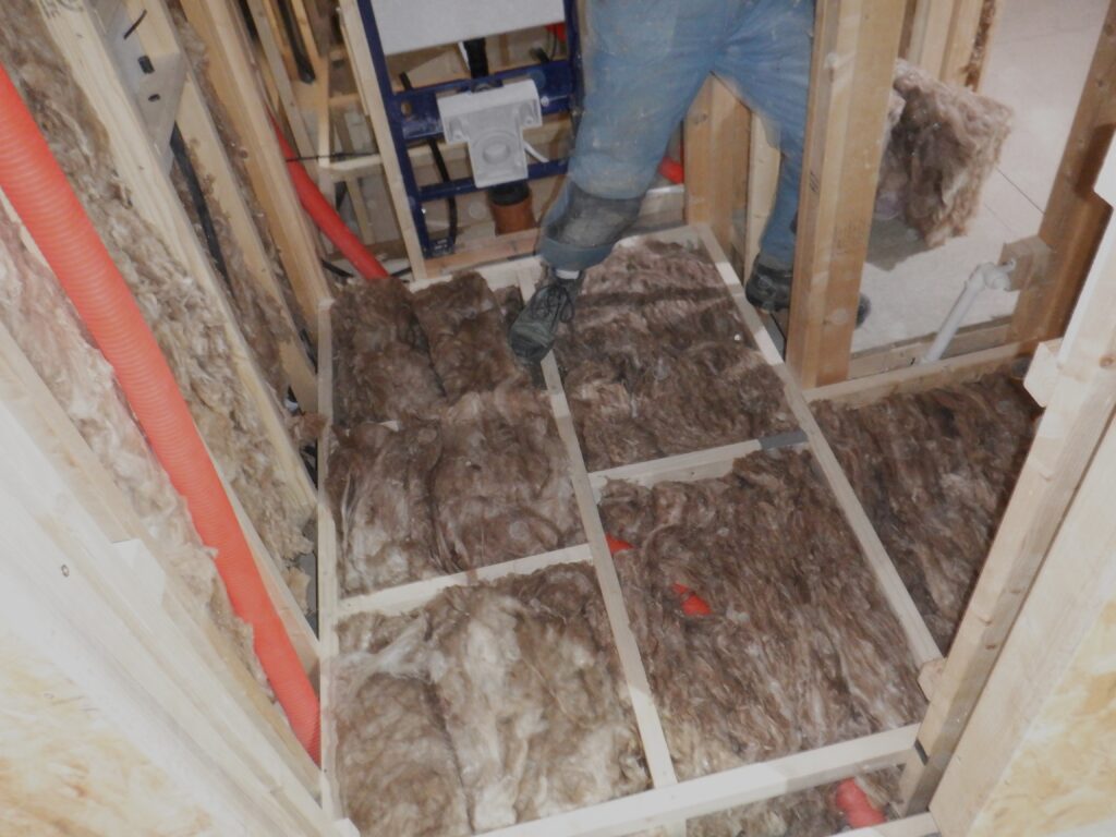
Cloakroom floor insulated
Then we glued and screwed the floorboard pieces that were already done (years ago!).
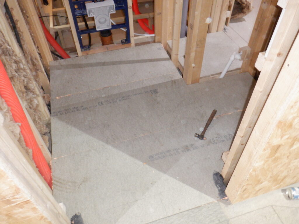
Cloakroom floor down
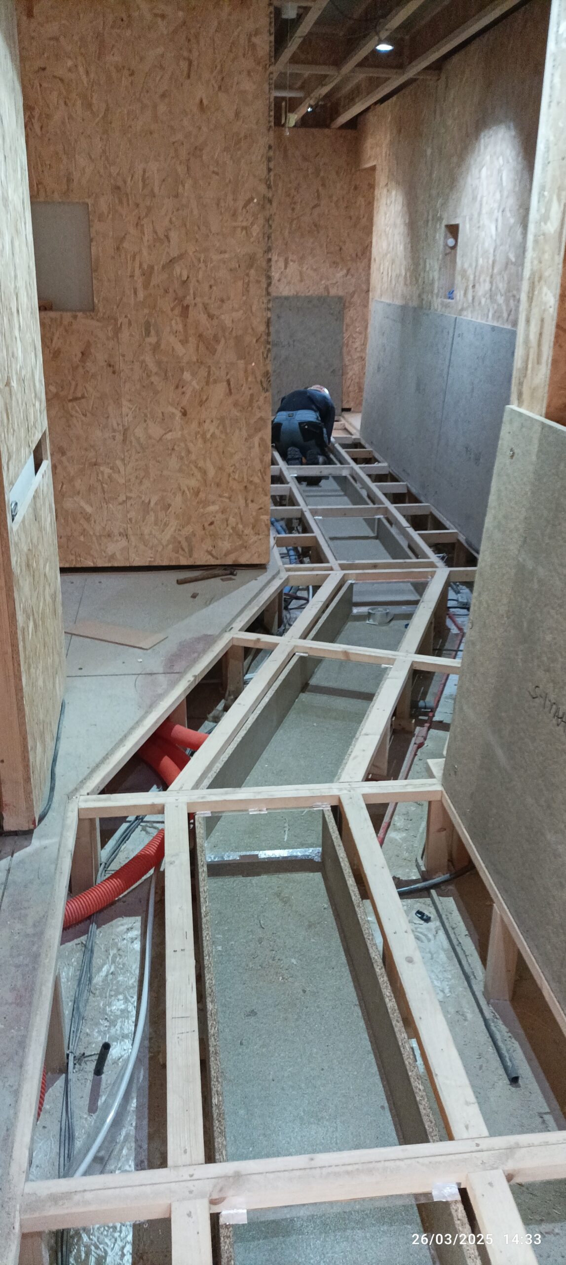
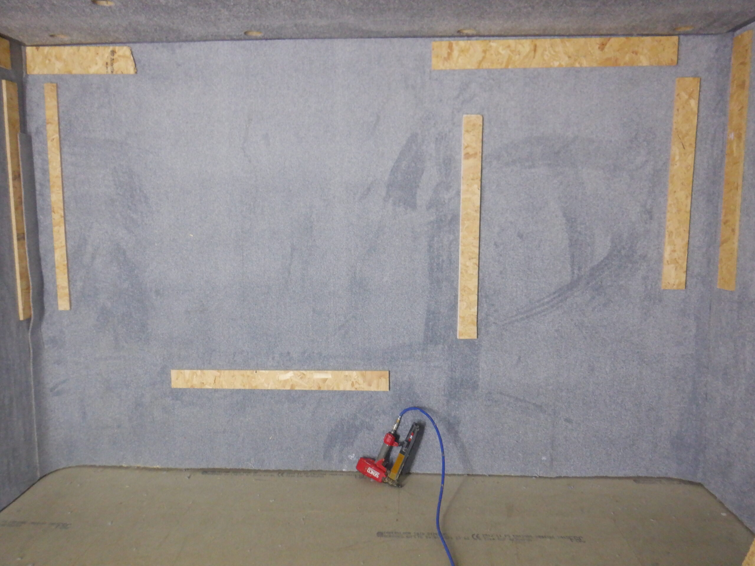
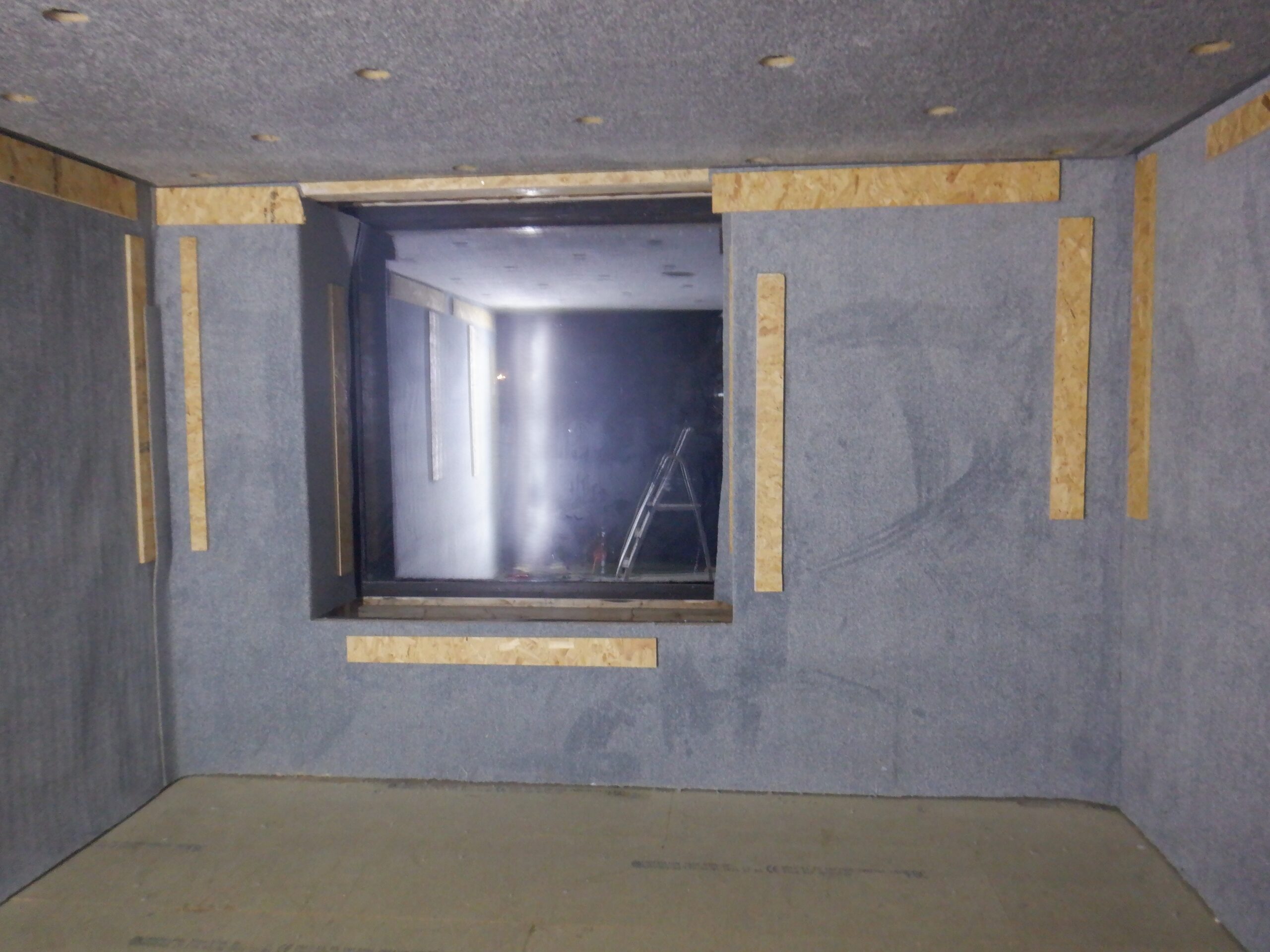
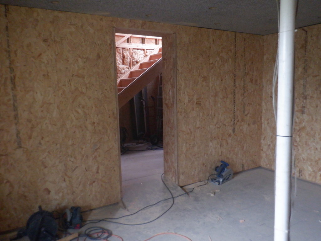
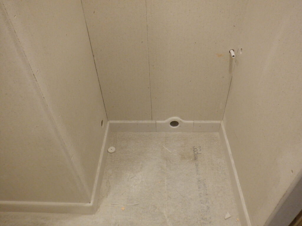
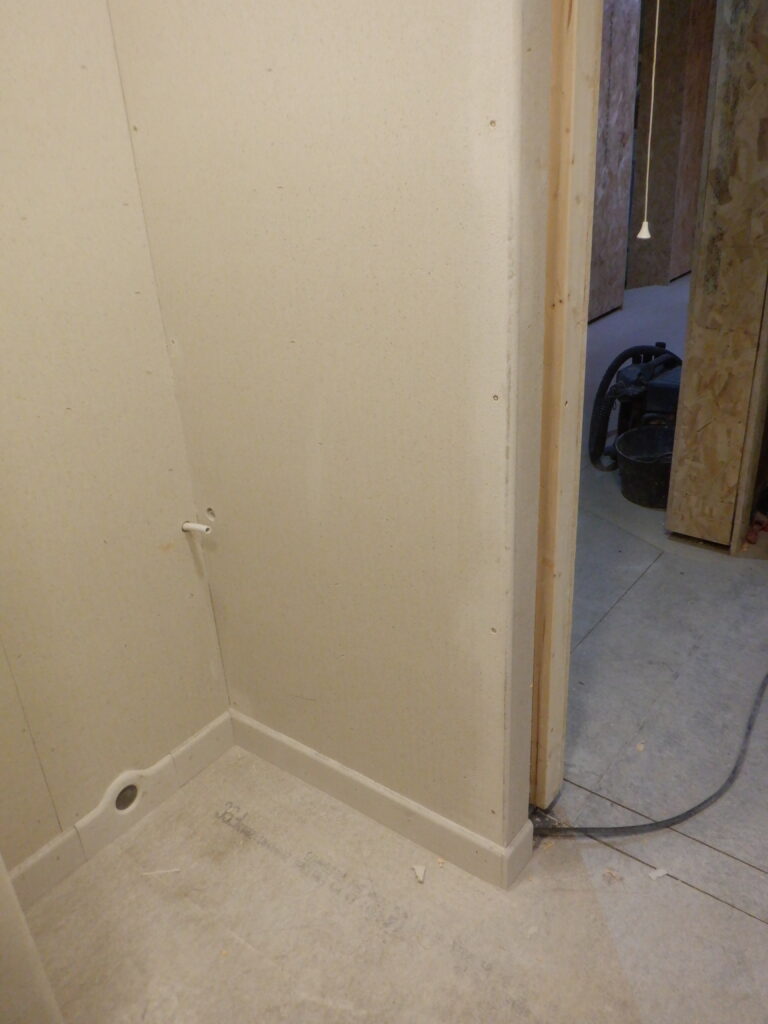
This meant that we can now, and did, install the first layers of wall boards. The first layer is the usual 18mm OSB sheets and we worked our way around the room, doing each wall segment. Some of the pieces had pipes sticking through, like the 32mm waste pipe socket, waiting for the pipe to come from the basin, the bigger 68mm air ducting and the 15mm hot water pipe, to connect to the spout sitting on the Vanity unit. The tricky bit was the toilet wall, because it had two round holes to put in, plus also the “access” panel to the cistern, but also, a future rectangle access panel just above the ceramic bowl itself.
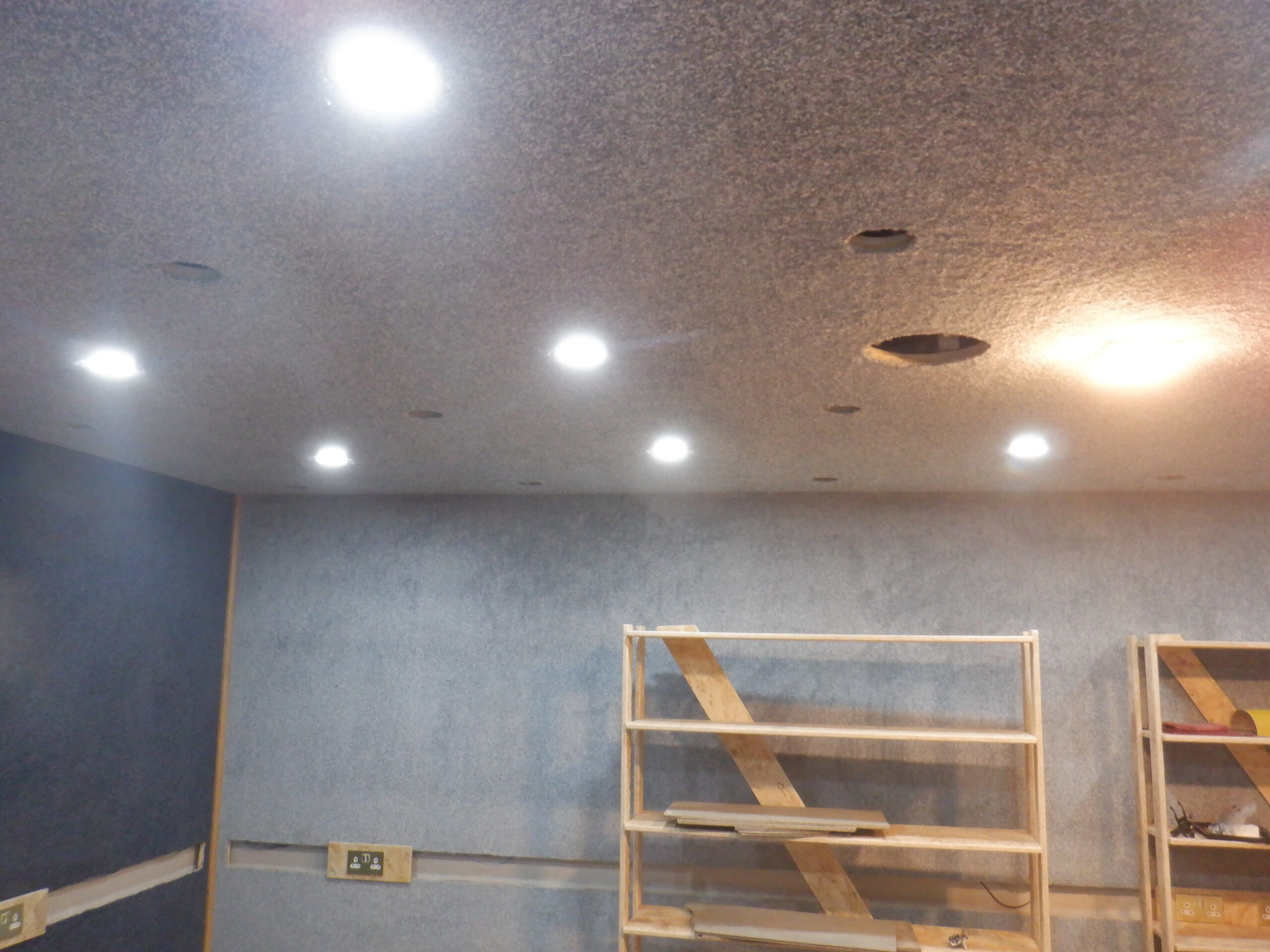
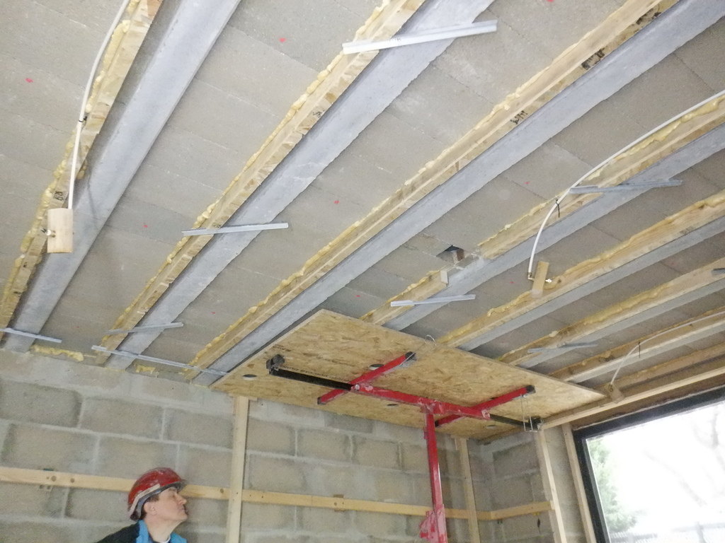
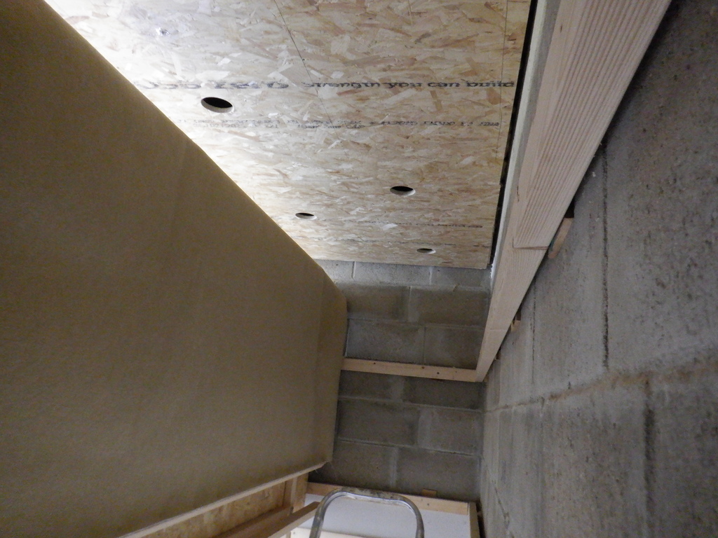
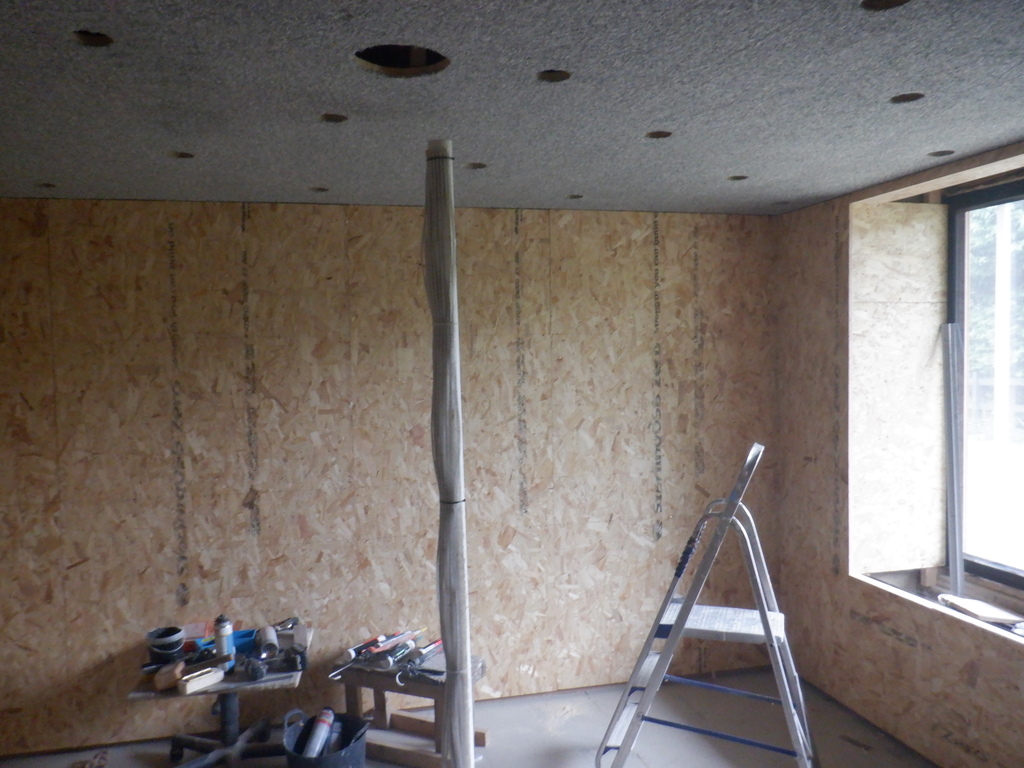
At this point, we decided that we would install some additional lighting into the Cloakroom so we could see what we are doing better! We had various samples of LED lamps so we gathered three of them together and placed them on short pieces of 12mm thick plywood and hang them up inside the ceiling space so that they don’t intrude into the room itself as we will be moving around and fitting large pieces of our plasterboard sheets. We wired the lamps back out to the Hall and put on a pull-cord switch for a local control when we have turned on the Hall lighting.
The next job was to trim the excess OSB material away from the door edges and also to cut out the Utility Channel that is beside the Vanity unit as well. At this point, we had a sudden thought that we had forgotten to make some provision for a future installation of more sensors and controls in and around the Vanity Unit itself, like detecting when the water is overflowing, or controlling the water by tapping the spout. So we needed an additional 20mm conduit installed, coming from inside the proposed Vanity Unit cabinet and going up to the Utility Channel we had just cut out. But, in order to do this, we had to sliced away a small portion of our new wall, to expose the hollow wall and the lower part of the utility channel framework itself. There, we drilled a 22mm down through the CLS timber for a conduit to fit through. We then took two pieces of our 20mm wide rigid plastic tubing and heated them to bend them 90degree right angles in them. Them using a small piece of 25mm wide water pipe, we could join the two halves together to form a single continuous conduit, going through the aforementioned hole. We finally, drilled a 20mm hole through the OSB cut-away piece, and then glued this piece back into the wall again. We will sand it all down once the glue has set rock hard and it will all disappear when we cover the walls with our plasterboard material anyway!
Next, we sanded all the wall surfaces, to remove any splinters and roughen up the surface, ready for the glue. We also gently washed the walls down with a damp cloth as well, to remove the dust.
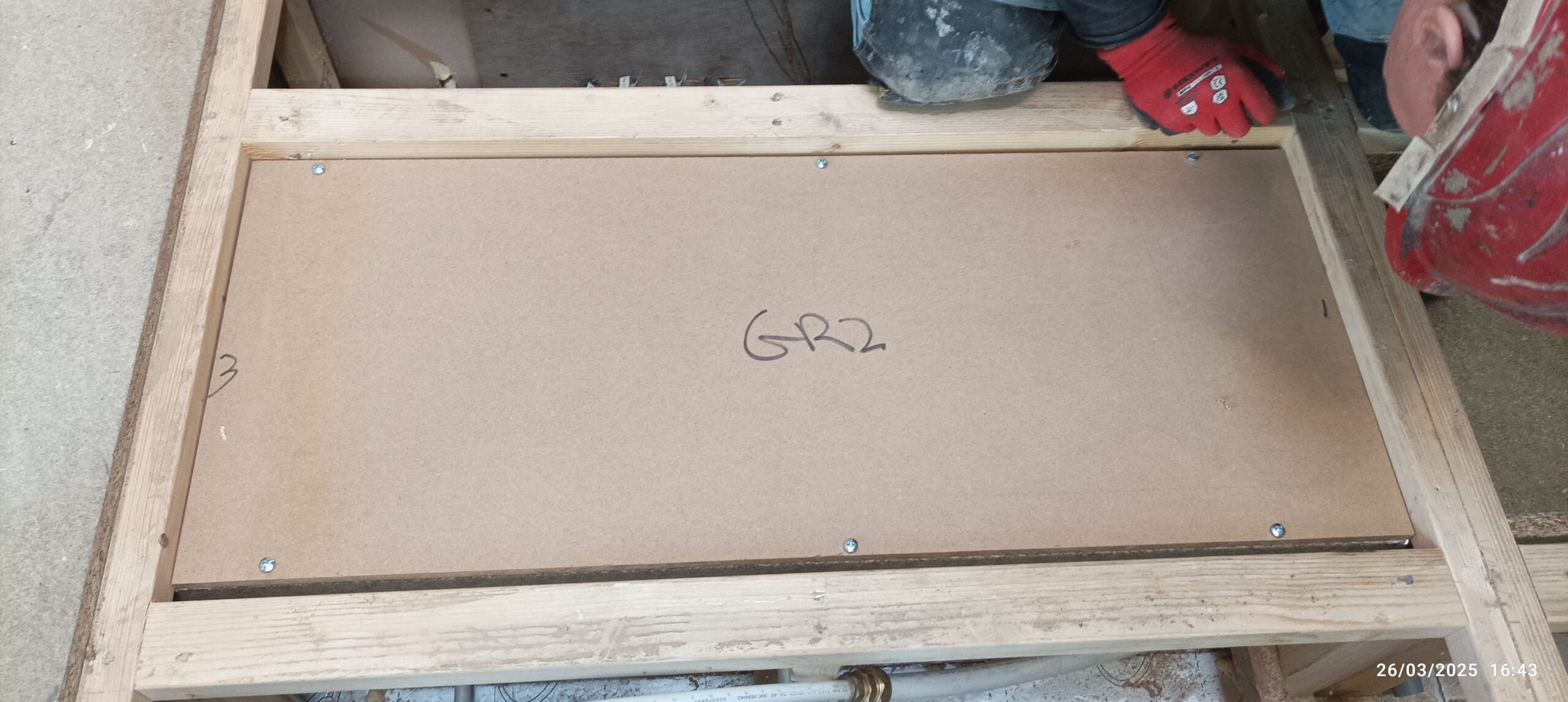
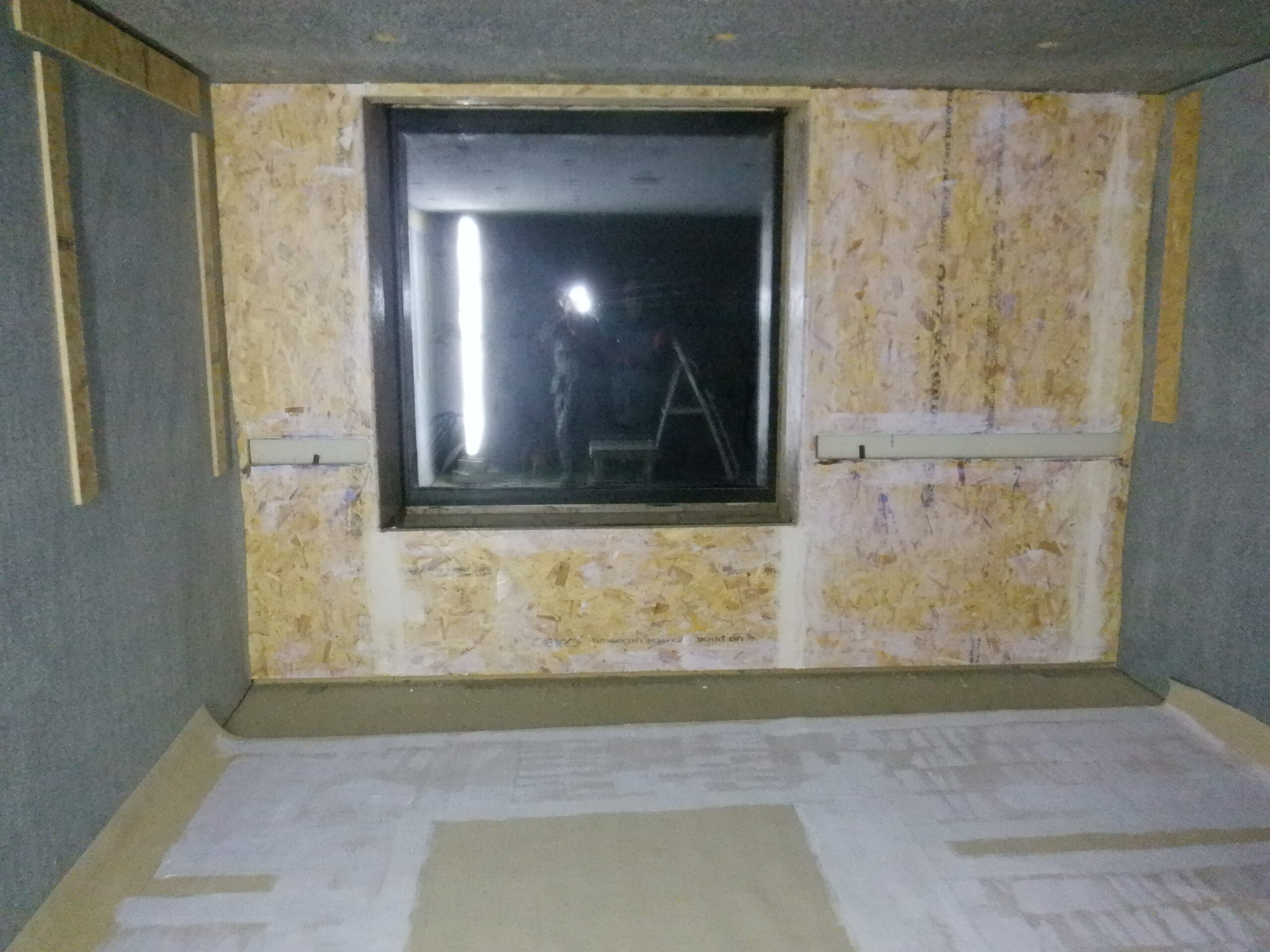
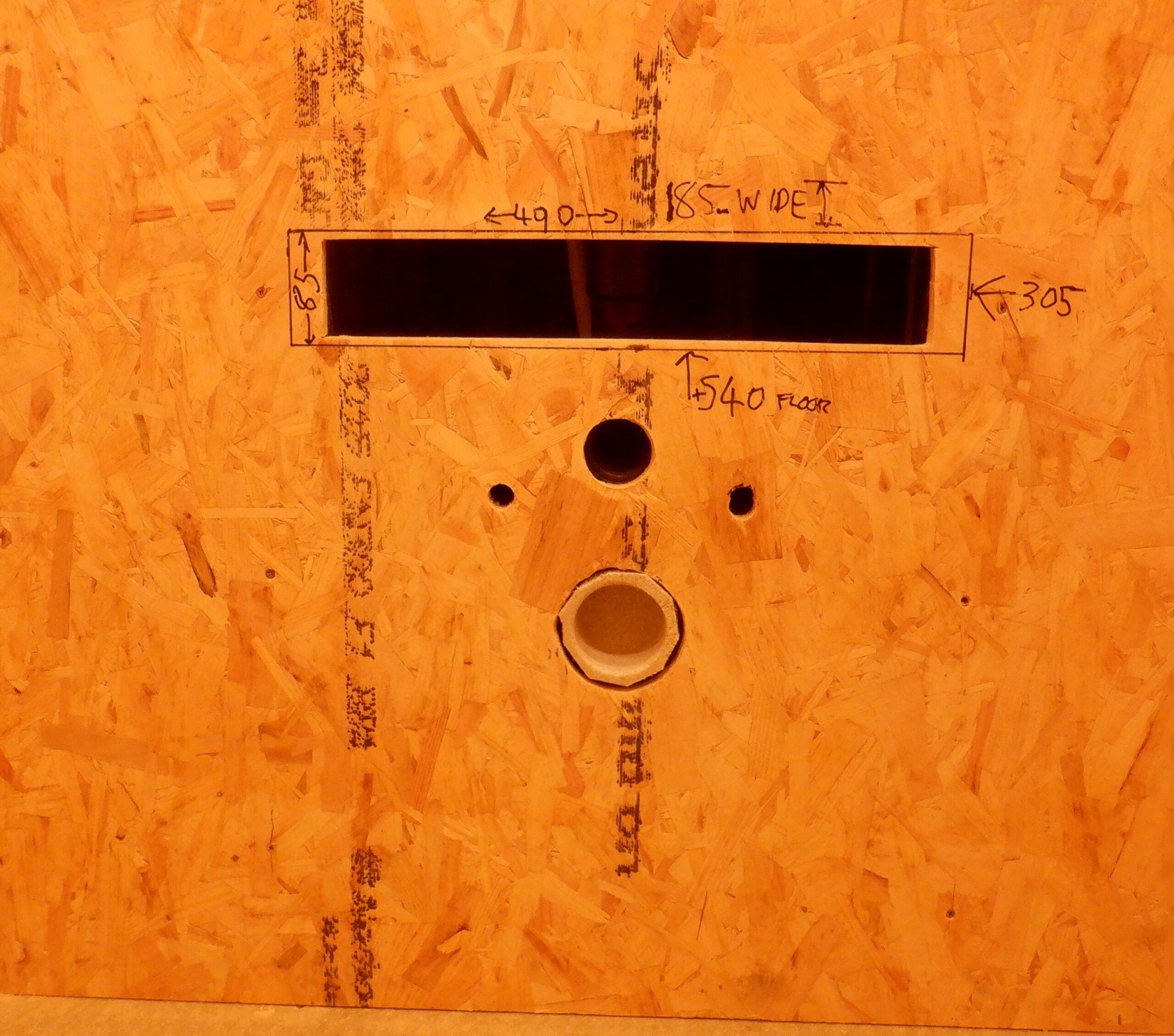
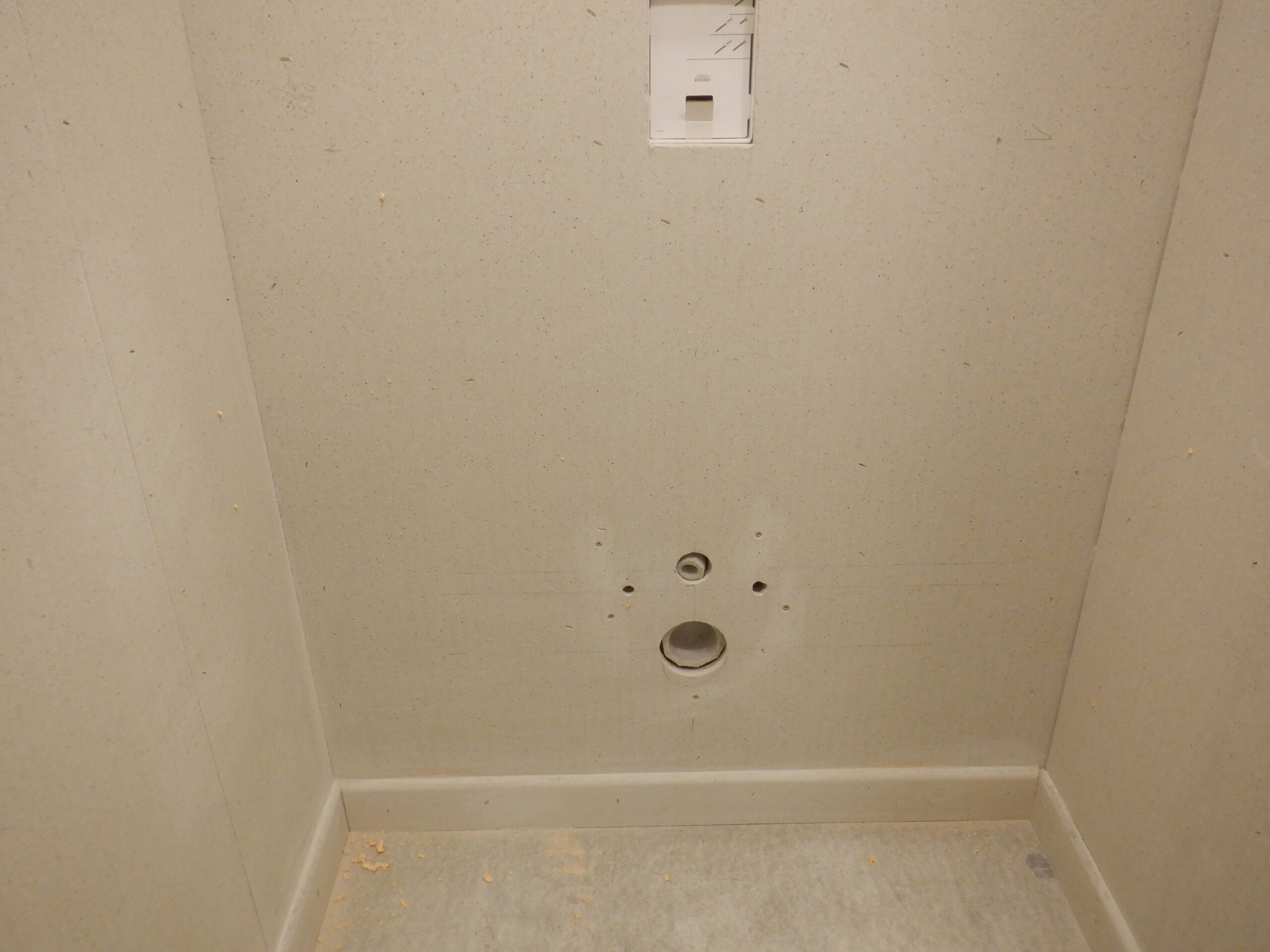
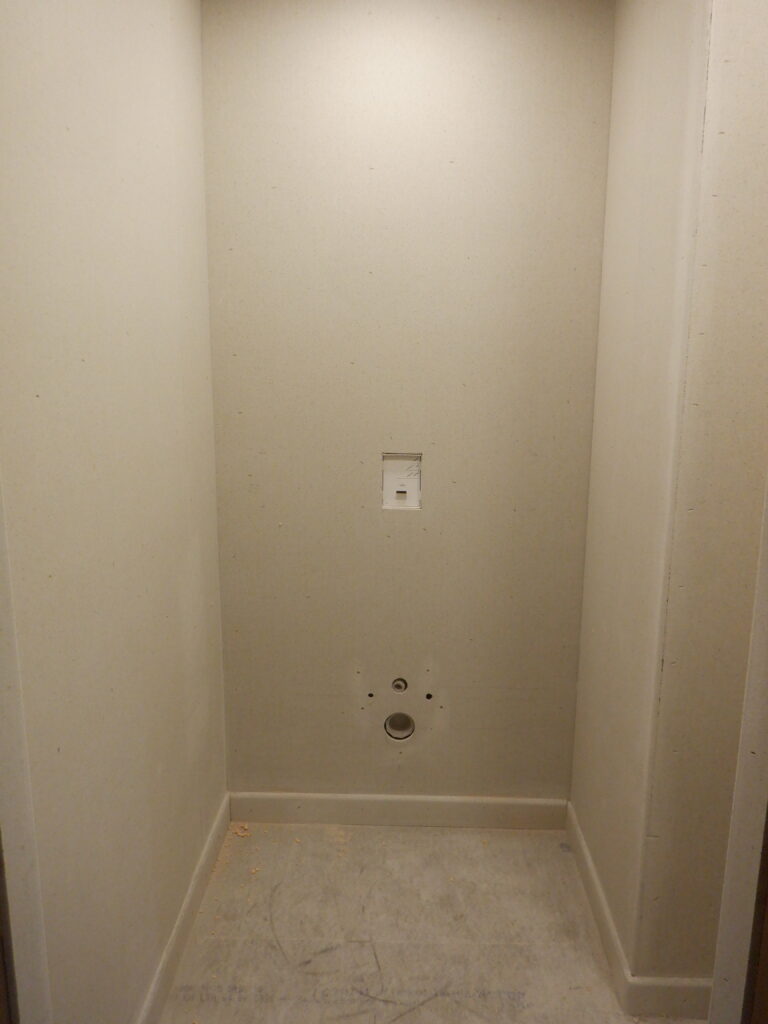
Now, we can proceed to put on the Fermacell boards (our high performance plasterboards), and started on the back wall where the toilet will be hanging. We measured the locations of the various holes, including the “letter-box” future expansion, we drew a thick black line around the edge of the rectangular hole, wrote the exact measurements on the wall itself and then took several photos for future records ..

Cloakroom WC Slot dimensions
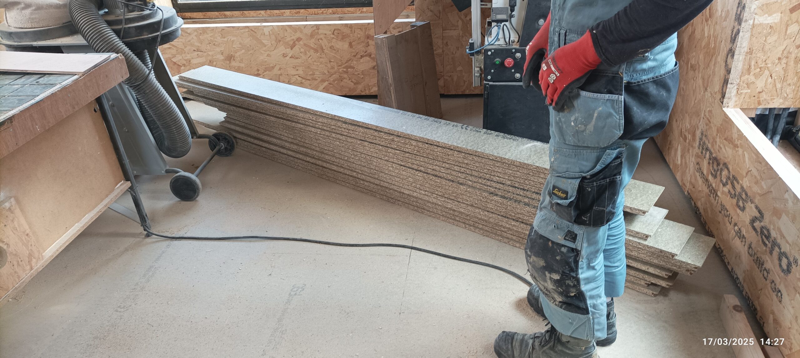
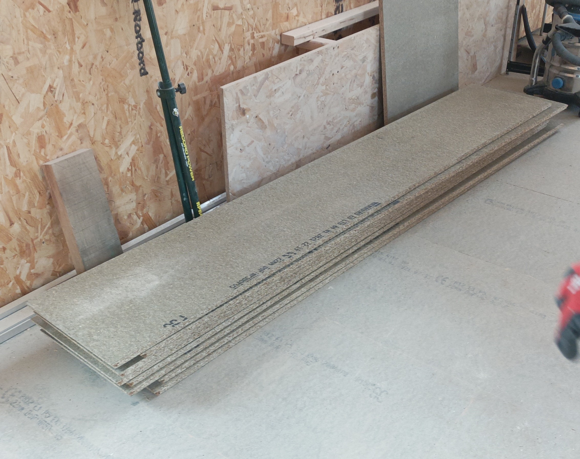
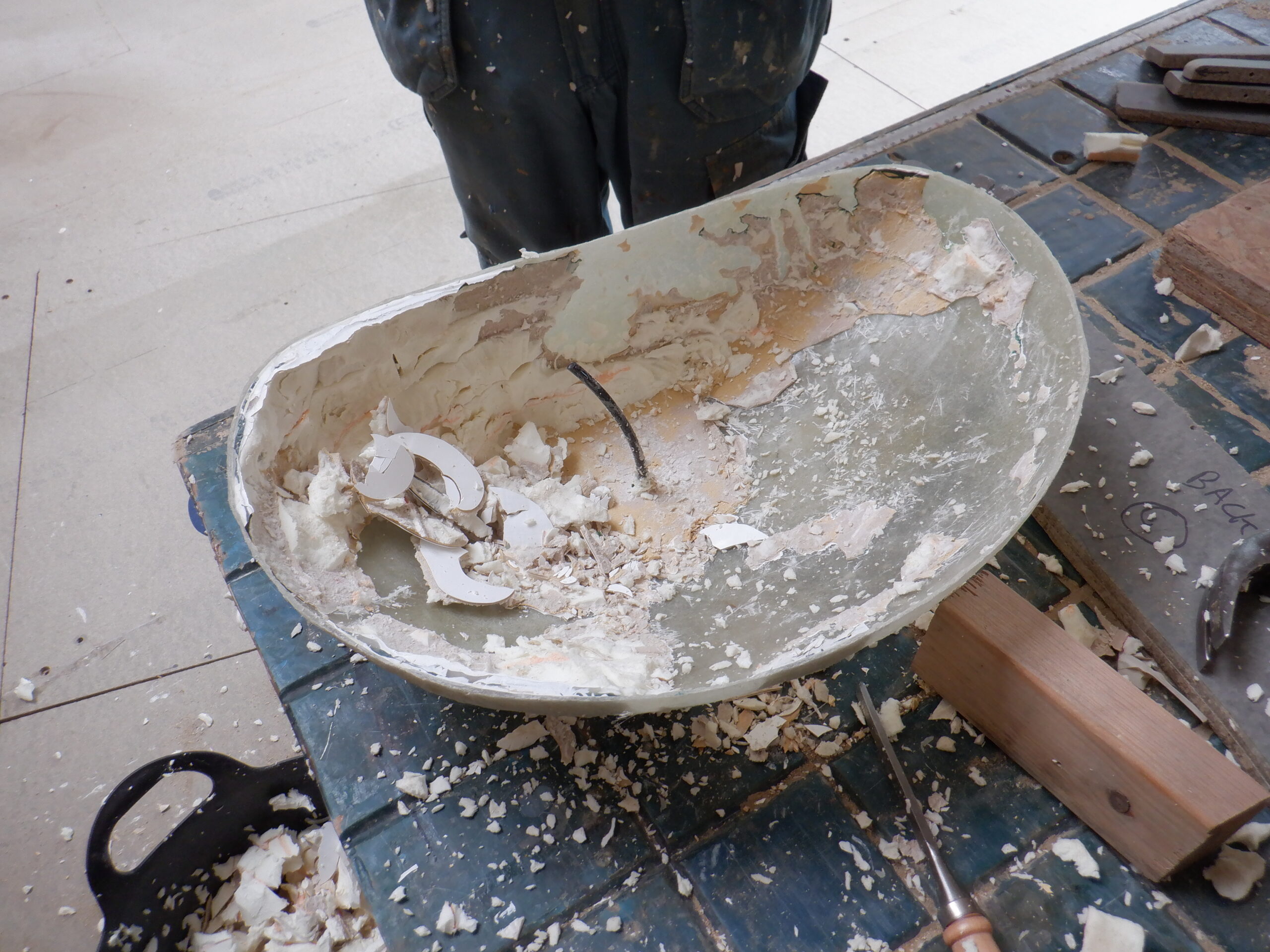
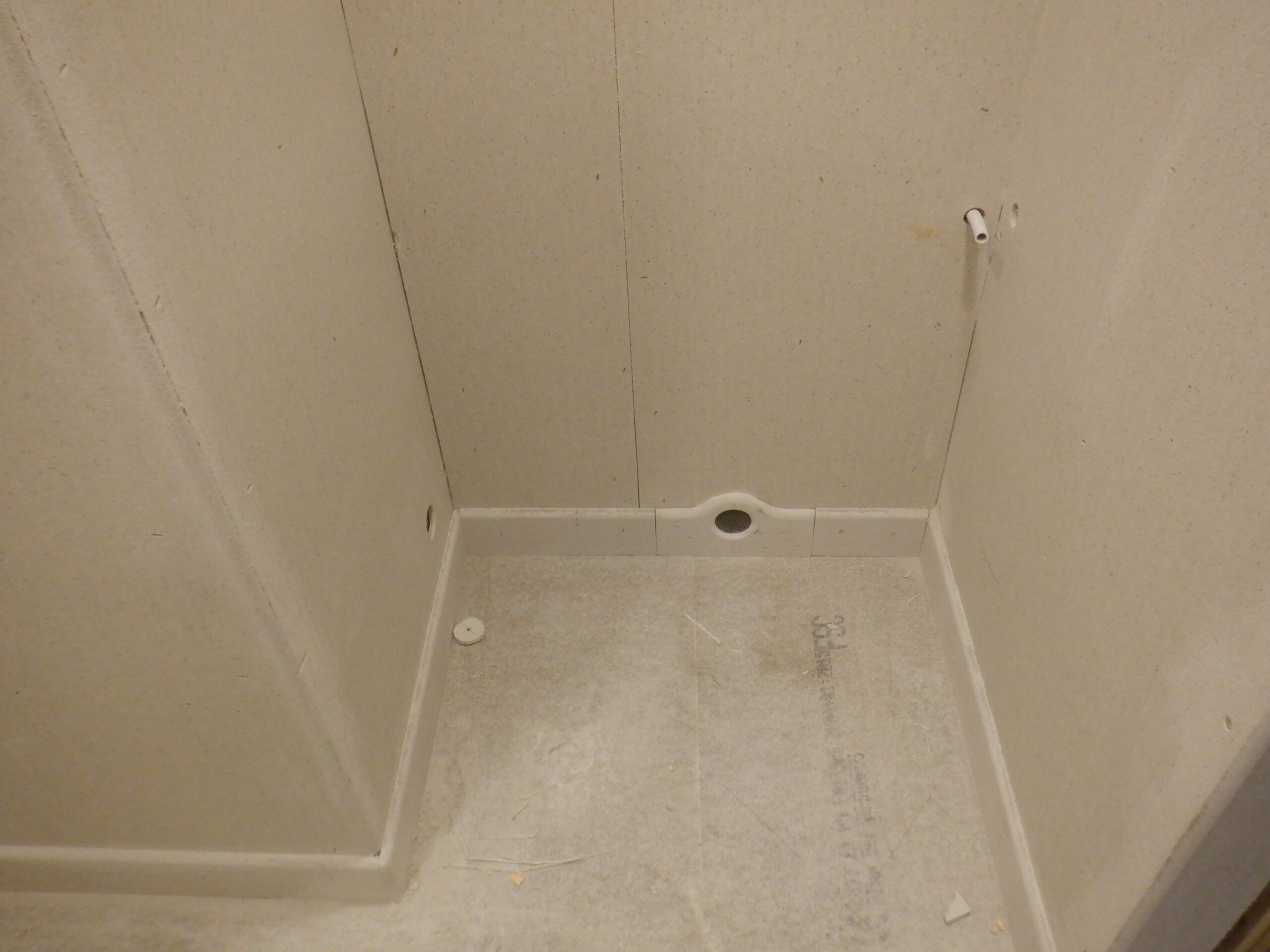
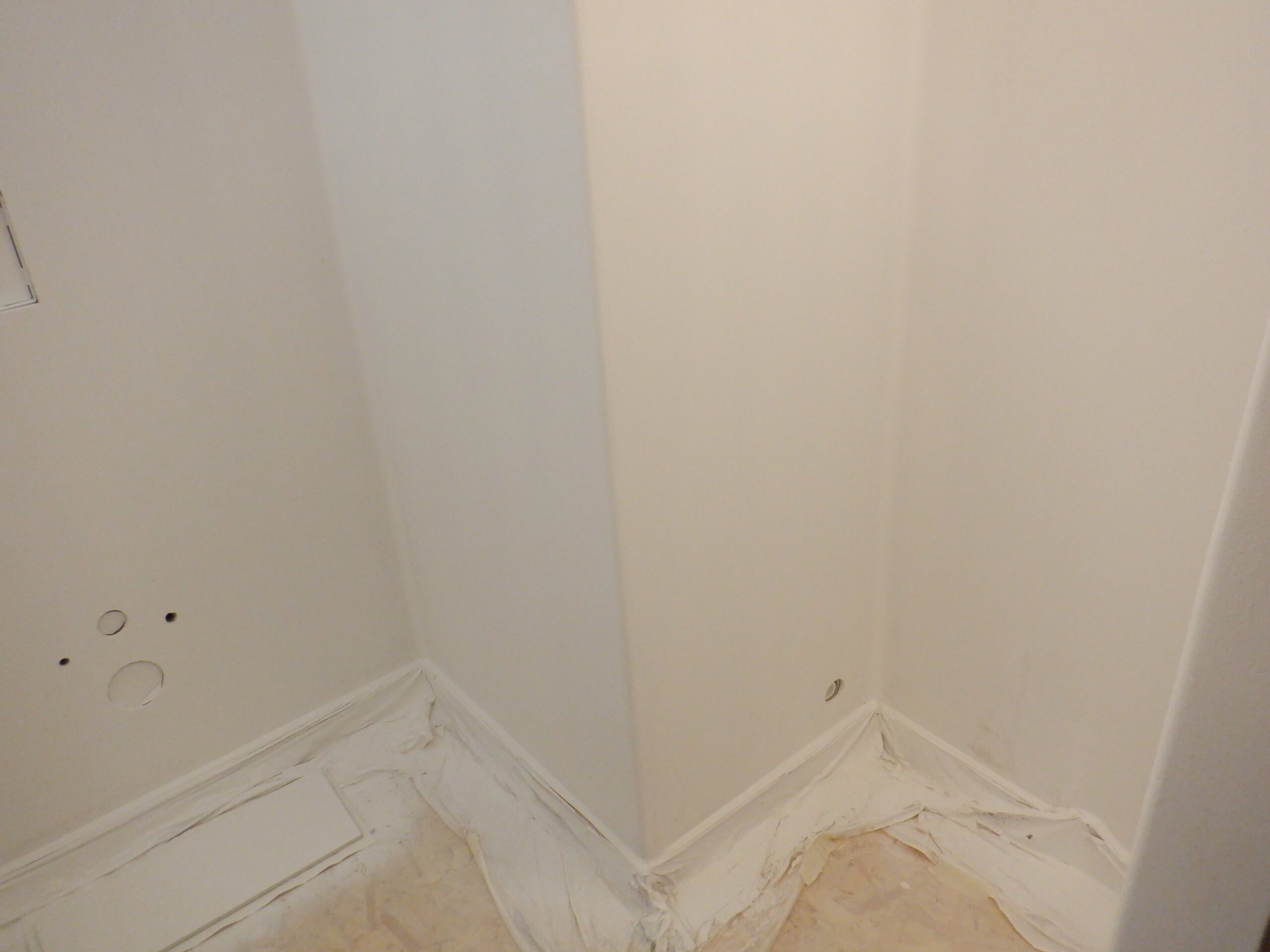
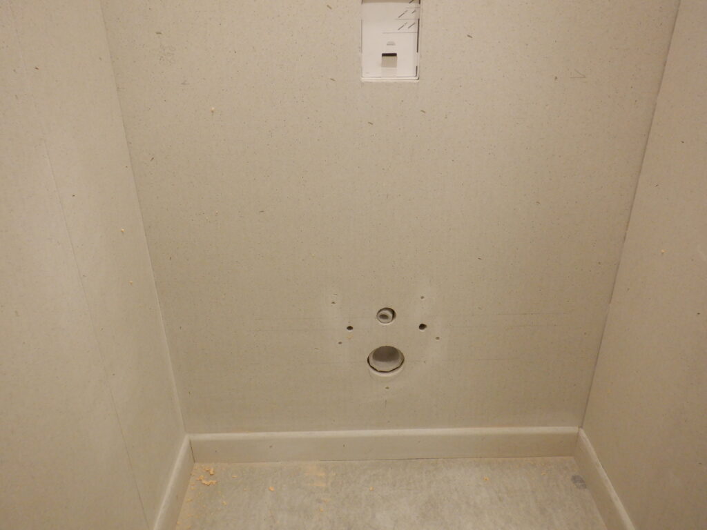
.. and we continued to measure the other holes etc. The width of the wall in total was 1100mm so we collected up a sheet off our pile and took it to the Great Room where we had our working table set up. We marked out the newly measured locations of the four round holes (one large one, one medium one and two much smaller ones for the bolts) and the large rectangular hole for the “pretty” plate that has the flush buttons on it. These got drilled and sawn, as well as the whole sheet was sliced narrower to that 1100mm width. We test fitted the board back in the Cloakroom and we only needed to rasp some of the edges a little bit, to make them fit smoothly. Once we were happy, We dampened down the back side of the fermacell sheet, and sprayed PU foam glue all over the wall, put extra construction PU glue around the toilet holes and pressed the sheet into place. We then stapled it all over and screwed a half dozen of short screws in and around the various holes, to make sure that the fermacell is well and truly squashed flat against the OSB board, so that when the ceramic toilet bowl itself is bolted into place, it won’t crush, wobble or damage the fermacell material.
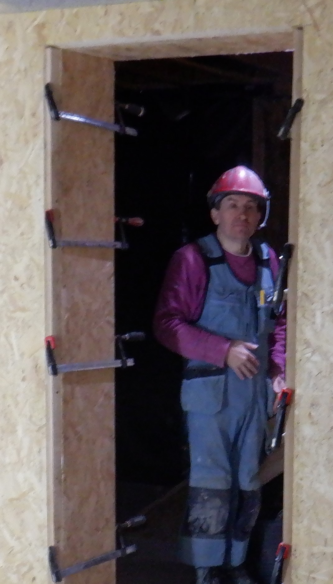
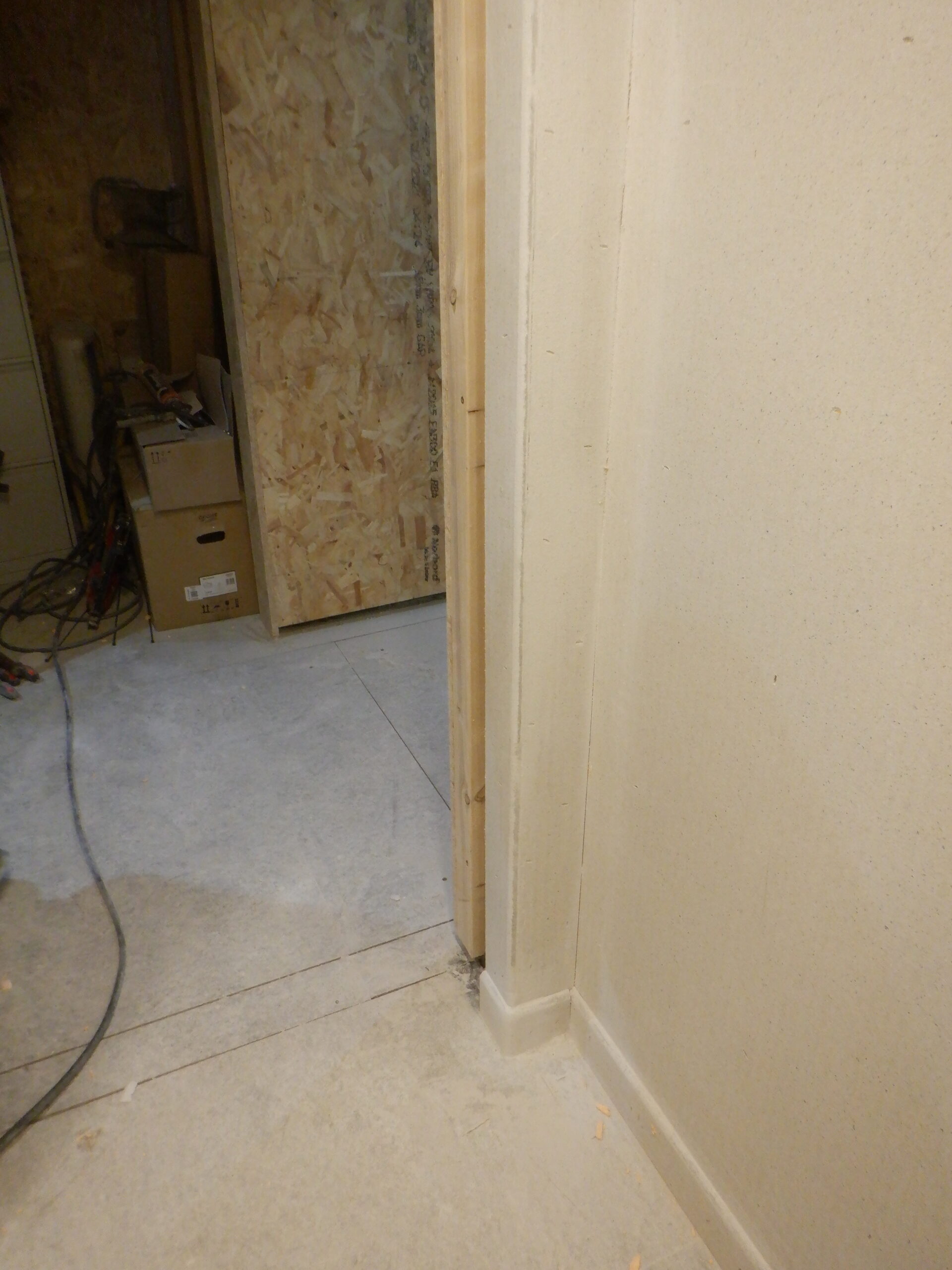
We proceeded to cover up the other five surfaces in the room, including doing the surrounds around the door entrance way itself.
Cloakroom Fermacell Up (1)
Cloakroom Fermacell Up (2)
Cloakroom Fermacell Up (3)
Cloakroom Fermacell Up (4)

Cloakroom Fermacell Up (5)
Before we could get on with doing the next step with the skirting boards, we needed to trim all the corners, plus also slice a small radius on the outside corners (the two vertical edges and one horizontal edges of the doorway, and also the corner of the linen cupboard). We had to open both of our doors to let out the cloud of fine gypsum plaster dust to slowly drift out of the house!!
The next job was to put on the skirting board, but not a traditional wooden kind, but, made up using more fermacell material, cut to produce a heap of 100mm wide strips. We recycled many of old left-over pieces we had lying around on our sheet rack and from doing the current covering of the Cloakroom’s walls. But before gluing and stapling them on to the bottom of the walls, we passed them through our table router which had the giant quarter turn of a circle router bit and adjusted so that it sliced off a glancing chunk of the fermacell, to make a smooth and slightly elongated curve at the top of the skirting board pieces.
We went around the whole room, which adds up to about 6metres in total, gluing and stapling each piece in place. The only section that needed special treatment was the section underneath the Vanity Unit, because it is where the fresh air comes out into the room. So we make a special piece where we curved up and over the “hole” and then filled in on either side with smaller lengths of the skirting boards.
We then sanded the three outside corners, to make a gentle bend around from one line of skirting to the next line. All these skirting boards will be ultimately covered up with the glass fibre resin combination, going right across the floor and making a waterproof sealed surface.
Next, we filled in all the staple holes, rubbed down the occasional joins, and filled in the five inside corners and smoothed down by using a 32mm diameter pipe, to produce a gentle rounded contour. We did the same with the floor to skirting board edges but this time used a 50mm diameter pipe so the fibre glass and resin covering will smoothly curved around up the edges, to make it nice and easy to wash the floor. We went around putting a little bit more on the vertical contoured corners, to help fill in small gaps etc. and then rubbed down using a piece of sandpaper stuck to a short length of the 32mm wide pipe so that we could end up all nice and smooth.
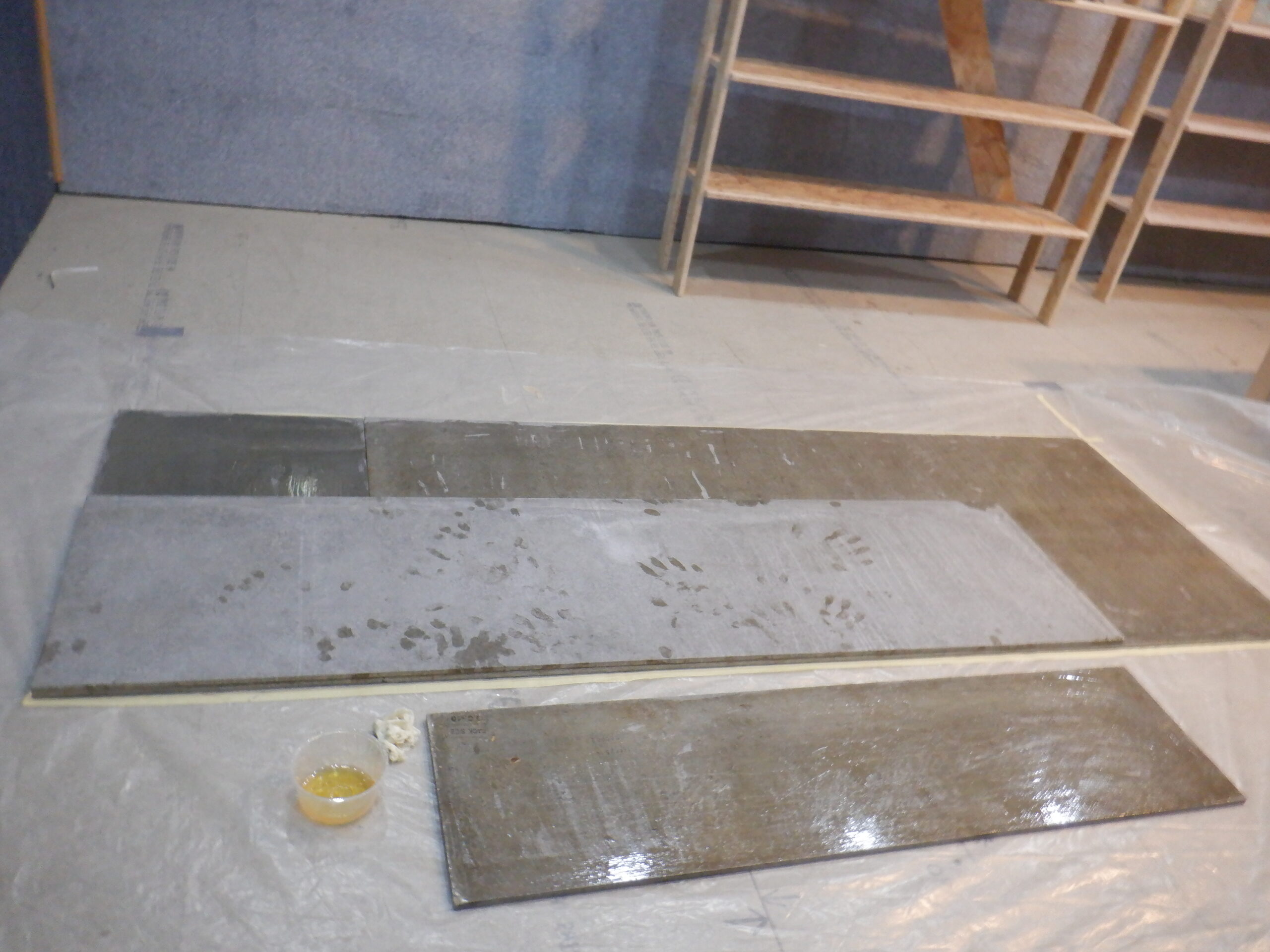
We also have been testing various combinations of fibre glass and resin on test samples of the chipboard flooring material, to see how well it sticks down etc. We also painted fermacell pieces too. Then, we coated some of them with the finishing “top-coat” to see how slippery it could be to walk on. The test revealed that it is very well stuck down and the white top-coat is not that slippery when it is dry.
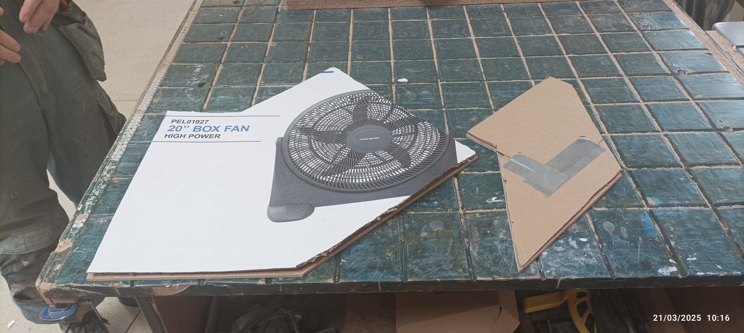
So with that in mind, we proceeded to prepare the fibre glass matting for the floor, tearing pieces off the roll, to put down three layers in total all over, with one layer going up the skirting boards around the edges. We needed to achieve this task of painting the resin into the glass fibre, in such a way, that we can reach over to apply the resin without stepping on to any “wet” parts. This meant that the pieces of matting had to be arranged so that each portion of the Cloakroom was completed fully, before moving along to the next section. We decided to do the area under the toilet first, then do the vanity basin section next, and then the middle section and finally the doorway area to finish off. These jigsaw pieces were bundled up and put into a line, ready for the actual application of the polyester resin. The doorway had an strip of 12mm plywood covered up in parcel tape, to make it non-stick and screwed down so the edge of the fibre glass can be terminated neatly to approximately where the sliding door will hang. This 12mm thick plywood strip is a guide to control how much glass fibre we should put down and we are aiming for a gentle slope going up when exiting the room. This will provide a double useful feature; one for keeping in any water spills and secondly, to make the transition from the hard, and much thinner floor covering, to the much thicker carpet and underlay that will be put down in the Hall. So, we had a pile of torn off pieces of the fibre glass matting, getting narrower and narrower, as we get closer and closer to the “barrier” defined by the 12mm plywood strip. This task took several hours to get right!
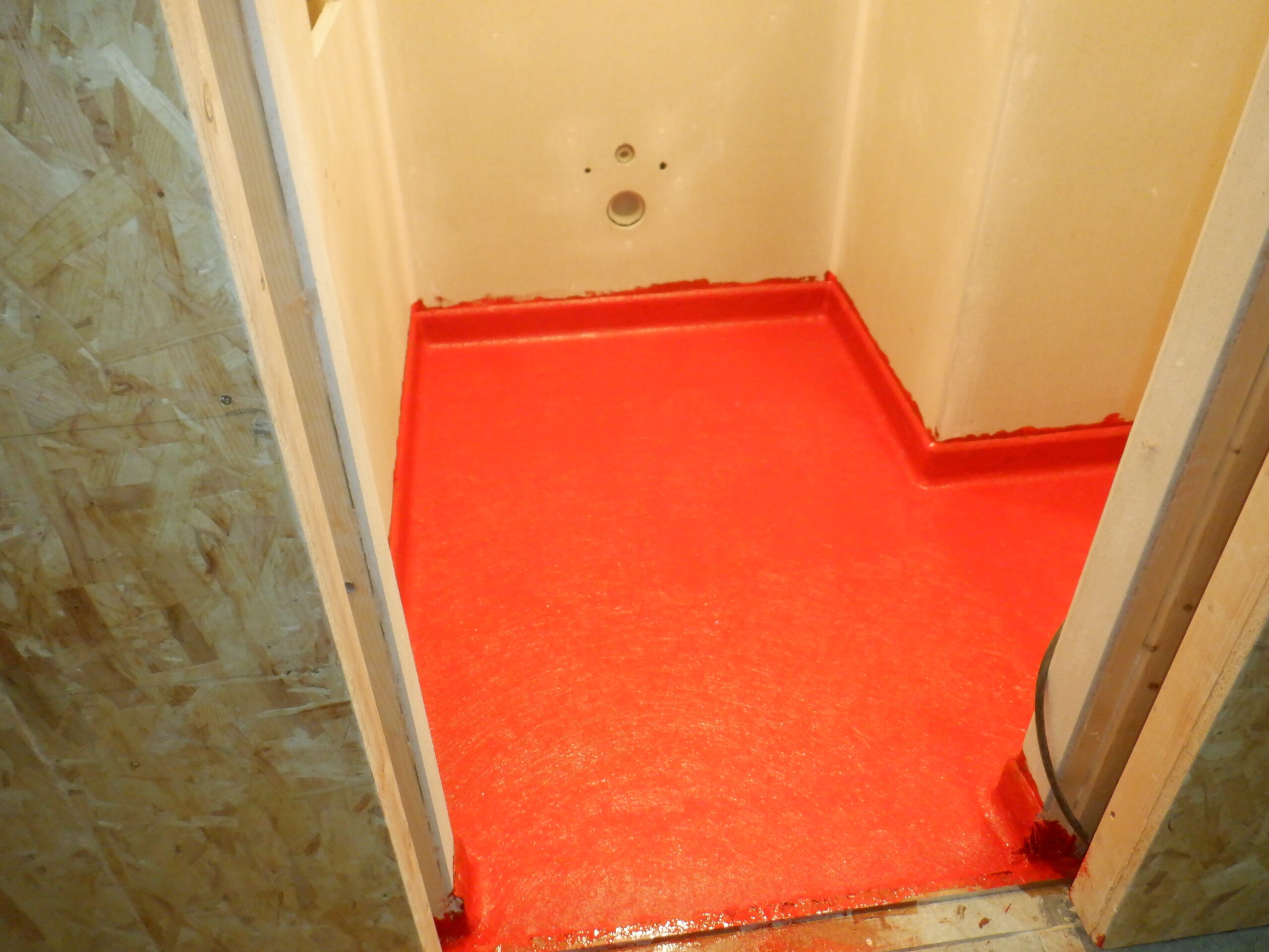
So after lunch, we got on with the job of mixing up the resin, we put in red colouring dye, to give it some interesting shade of colour and mixing batches, one for each section. We had five mixing pots so we started with 1.2kg of resin, put in 12ml of hardener and got on with the three matting pieces next to the toilet wall. We discovered that we needed to mix a further 500grams to finish off this section. Them, we proceeded with a 1.6kg of resin, to do the section under the Vanity unit and then moving across to the middle section with another 1.6kg of mixture. The last section of the floor had a 1.5kg of resin and then finally, an additional 600grams to build up the slope in the doorway. This took about three hours to complete this task, making sure that all the layers were pressed down, using the metal ribbed roller, to get rid of air bubbles and make sure the resin is well mixed with the glass fibre. All the skirting boards had plenty of resin brushed on them as well, as we were doing each area.

Cloakroom Floor main fibreglassing done (1)
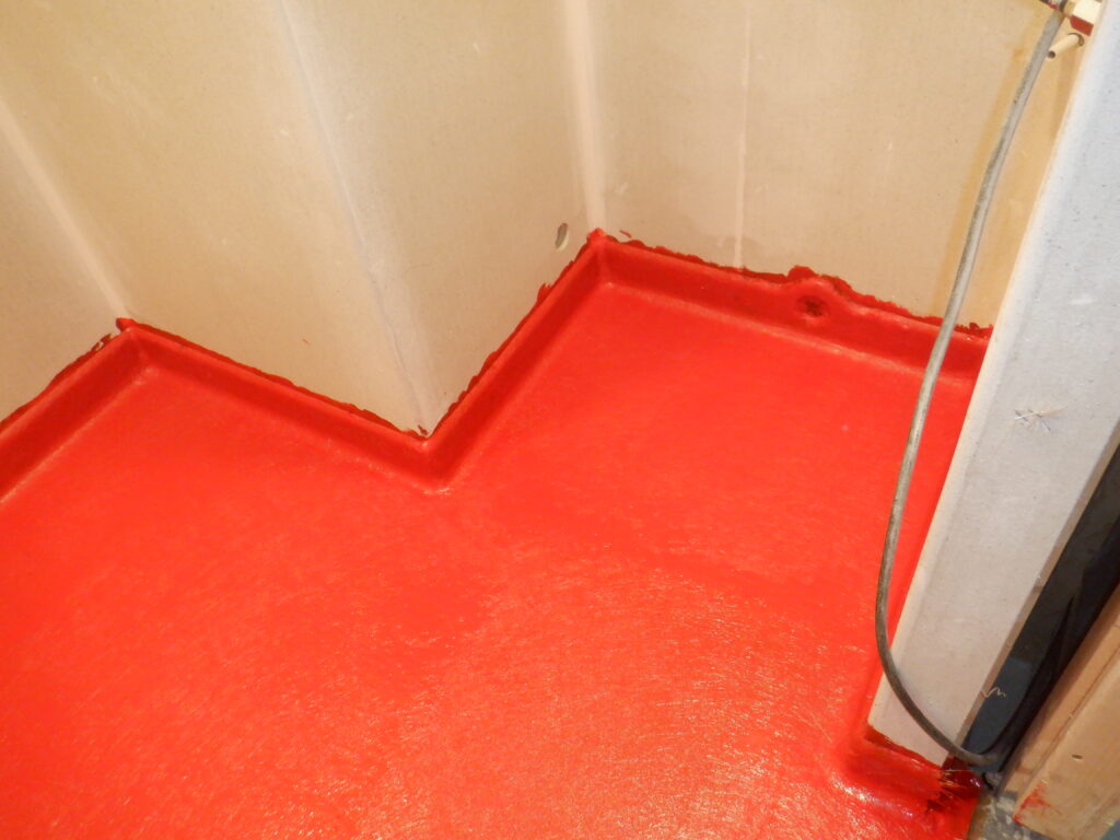
Cloakroom Floor main fibreglassing done (2)
We did come along and lay down another heap of glass fibre strips across the doorway, to build up the gentle slope, to raise up the surface so that it meets the carpet and underlay out in the Hall.
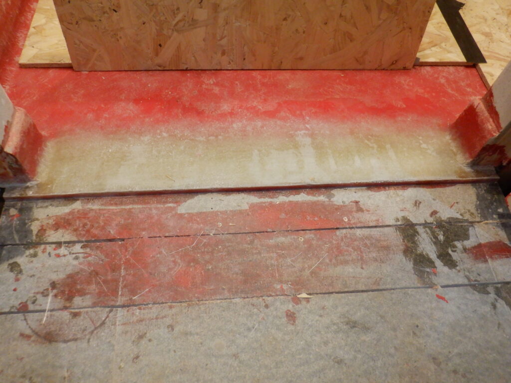
Cloakroom Raising the threshold
This is the basic floor covering, which we will double check for bumps, sand the surface to make it smooth and then apply a finishing coats, perhaps two coats, to provide the waterproofing seal to the whole room and 100mm up the walls. This final “top-coat” will be done later on when we have finished routing various conduits going over the Cloakroom before we install the ceiling fermacell boards and complete the whole room, including painting it and the walls with our colour scheme. Once that is all done, we then will do the final coat of resin on our floor!!
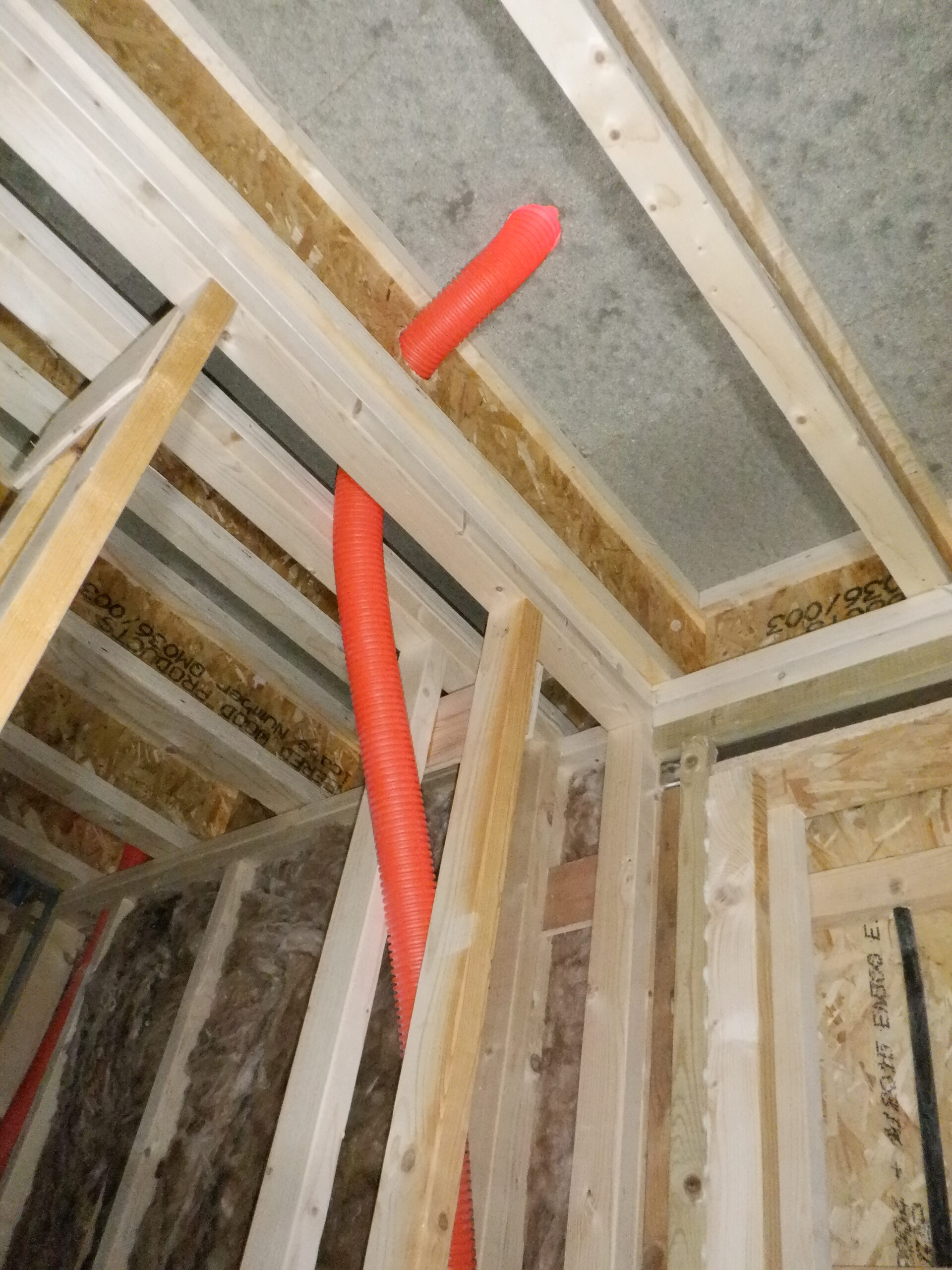
So talking about conduits, we did that task of putting any conduits up inside the ceiling space, see Installation of a Variety of Conduits from Tech Cupboard for details.
Next, we installed some lighting conduits up inside the ceiling, short 40mm flexible conduits that goes from one lamp position to the next one, and then another short length to connect to the outside world in the Hall, to join up with the controller board out there.
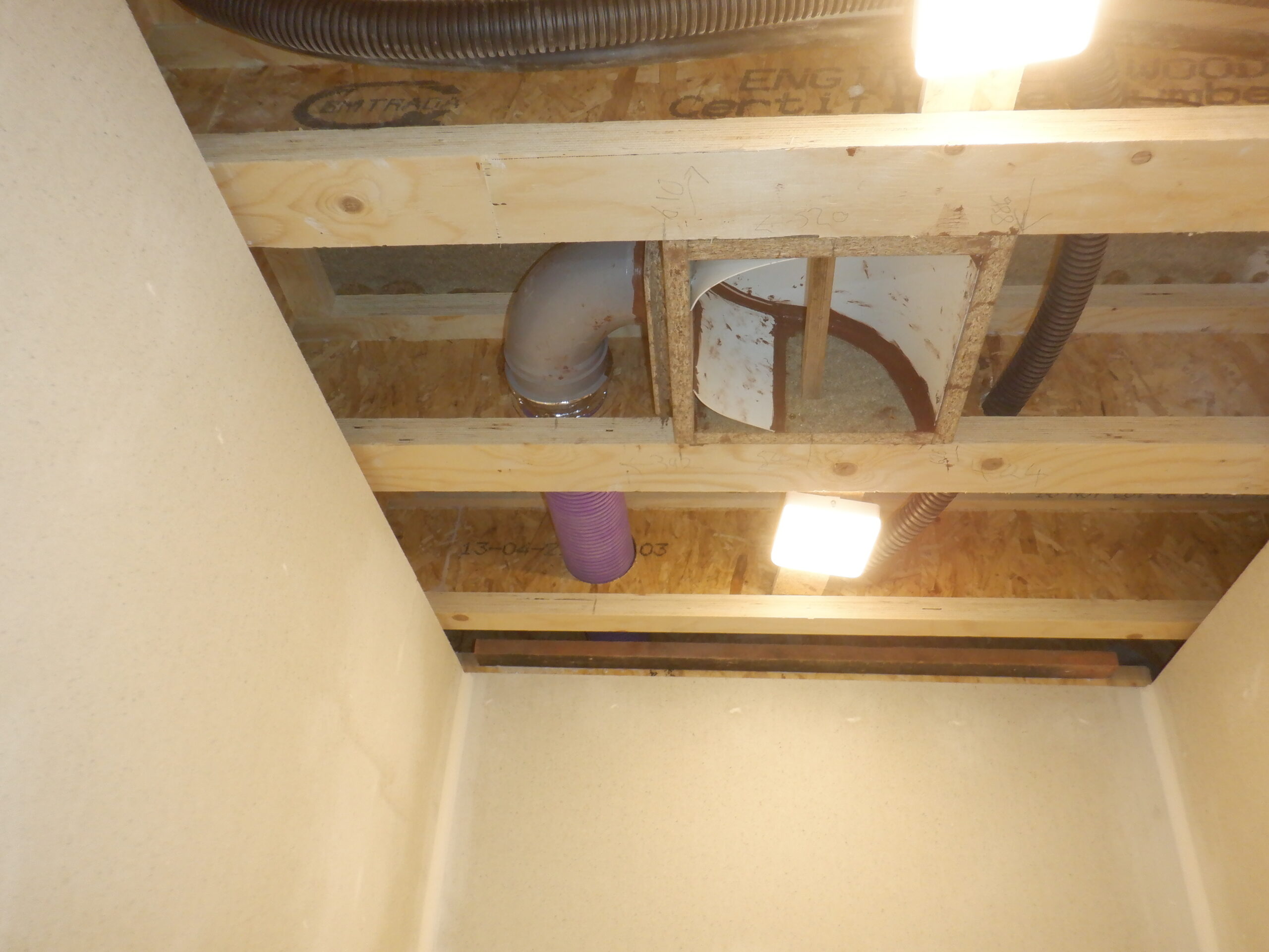
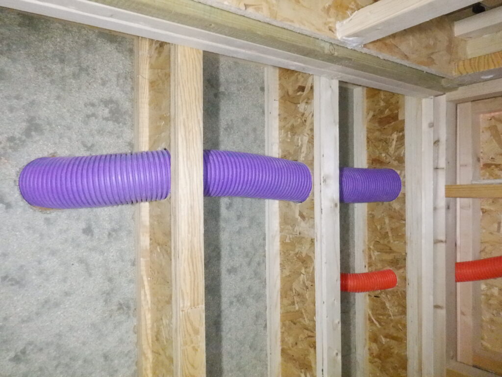
The final job to do up there, is to build an air ventilation module that will allow a circular “pretty” vent to be installed in the middle of the ceiling and then a 100mm diameter flexible pipe to come out the side of this module and goes through several joists, heading towards the main ventilation ducting that runs right around the whole house, up on the First Floor, inside the triangular void space. We constructed the module using pieces of left-over floorboards and glued and screwed it together to form a box. We then slid inside a piece of flexible plastic sheet, it is only 2mm thick and we cut it down so it fitted inside the box, but push it into a curve to help guide the air flow more gently around the bends. We also put in two little side wings as well, to guide the air towards the output pipe connector, which is actually a sweep right angle bend, with a socket sticking in the correct direction, to take our purple flexible pipe that will go through the joist as mentioned above.
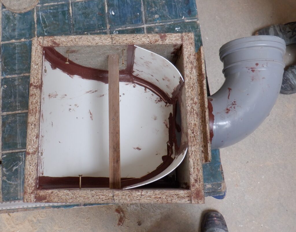
Cloakroom Air collector
The last piece to put in is a small bracing wooden bar across the box so that the “pretty” air vent cover can be fixed up against the ceiling surface later on after everything have been painted.
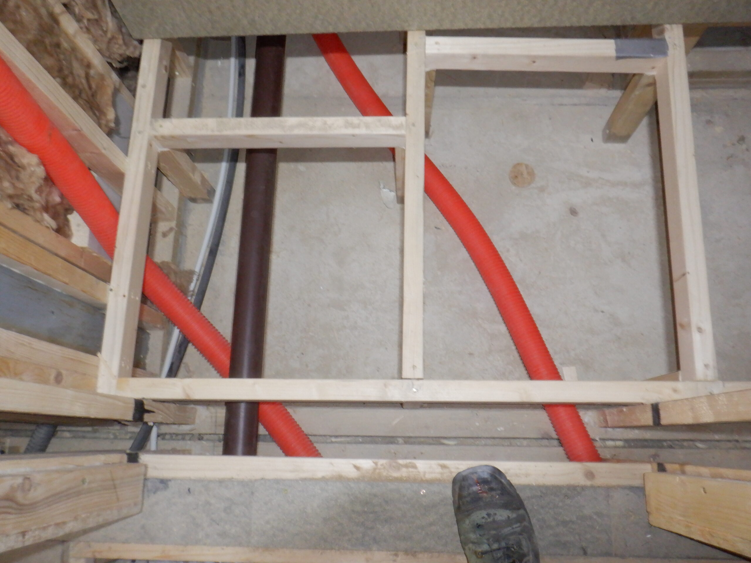
Now that we got our air vent module built, we push it up into the correct location, approximately centred in the middle of the room and marked off where the air socket is facing the webbing of the joist. After taking it out again, we proceeded to saw a series of 114mm diameter holes through five consecutive joist. We wanted the flexible purple conduit to poke up just before our main Air Duct which runs around inside our triangular void space upstairs. We drilled two overlapping large holes through the floorboard so it produces an elongated “oval” hole for the purple pipe to slide through at an angle and reasonably pointing towards the future Air Duct.

Cloakroom Air collection in place
Cloakroom air goes through joist and upstairs
We slid back the air vent module and screwed it in so it is all flushed with the bottoms of the joist and then pushed the purple pipe into the side socket and sealed it up with aluminium tape.
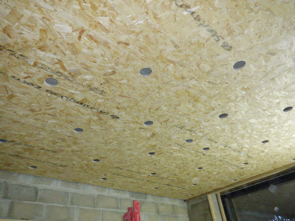
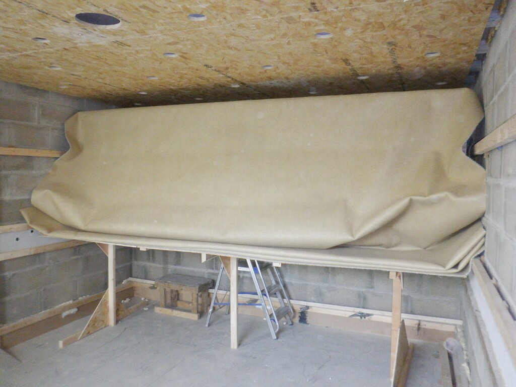
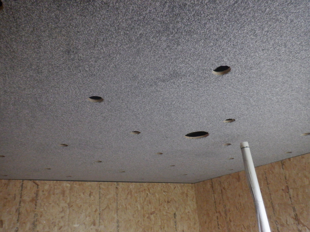
That concludes all the conduits and pipes that lives up in the ceiling space, so we could start the process of installing the fermacell sheets up there to cover up the joists .. at last! But, one of the first tasks to do, is to glue a strip of “2 by 1” batten around the edge of the walls so that we had a something to enable us to screw up the ceiling boards. Sometimes, the walls are positioned in between joists and there is nothing up there to secure the edge of the fermacell.
Next, is cutting smaller pieces of the fermacell material to build up the jigsaw pieces to slide horizontally into each section. It was quite an effort to work out the precise order. We took advantage of the joists running across the room, to act as a wide battens to allow us to butt together the two edges of the fermacell and have it nice and tight and flat, without having to do any major sanding. We got it organised so that we had only one tongue and groove joint to do, connecting the piece above the Vanity Unit and the two pieces over the door entrance. We ended up with four pieces.
![Construction and Decoration of Cloakroom]()
The next task is to drill various holes for the three lamps and a giant hole for the air vent. We didn’t want to have to cut these holes upside-down so we did it while we had the pieces loose.
Now, it is time to glue and screw them up! We used our construction PU glue because it has a much longer working time, to allow us to slide the pieces around, to get them joined together and hooked into place, before we screwed any of the four pieces. We even pre-started the screws while each piece was lying on the floor so we didn’t have to used two hands to hold up a screw and drive it in. It helped enormously, so much so, that we are considering buying another piece of equipment to automatically drive screws in, by just using one hand – the screws are held in a long strip which automatically feeds into the screw driver!!
We put up the piece over the Vanity Unit first, then the Toilet piece next, then the middle piece and finally the fourth piece over the door entrance way. We put plenty of glue on all the joists and battens, plus also the fermacell joints as well.
Next, we went around filling in the edges at the top of the walls, to form a gentle contour between the wall and the ceiling, at the same time, filling in the little gap that we had at the top as well. We used a 32mm diameter plastic pipe to shape the tile adhesive mixture, because we got loads of it, but also, it is very easy to rub it smooth afterwards.
We also put up our white concentric ventilation cover, in the new large hole, screwing it into place, plus also, we put in three flush fitting LED lamps too.
The next job is to rub down all these fillings and apply additional treatment to areas that didn’t quite “do the job” first time around. While these are drying, we carried on making the heat exchanger module for our Hot Tank.
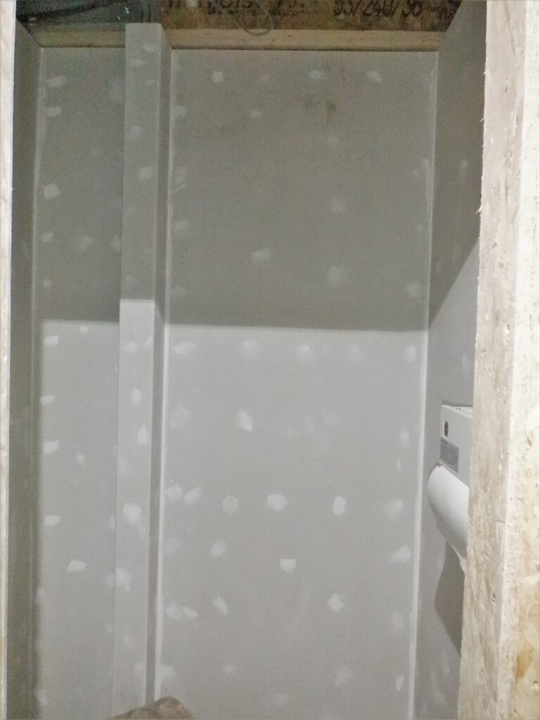
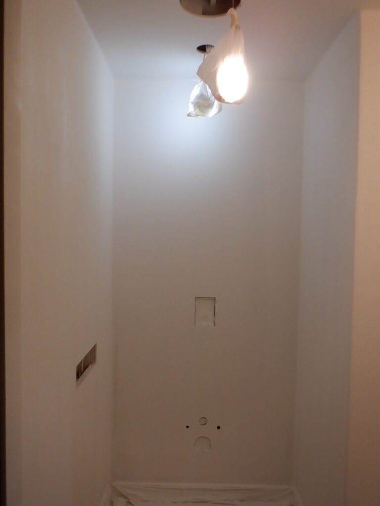
Now reaching this point in our Cloakroom, we proceeded to spray the walls and ceiling, with the first coat of white emulsion paint. Our very useful sprayer machine is a powerful machine and did a quick work of covering all the walls and ceiling. We took down the air ventilation grill and put little plastic bags over the three LED lamps and sealed them up. They still glow brightly so they are still helping us!
After the first coat, we went around and gently rubbed all the surfaces and discovered several missing holes which didn’t get filled in. We also spotted some of the joints between fermacell pieces that also needed more attentive work done to them too.
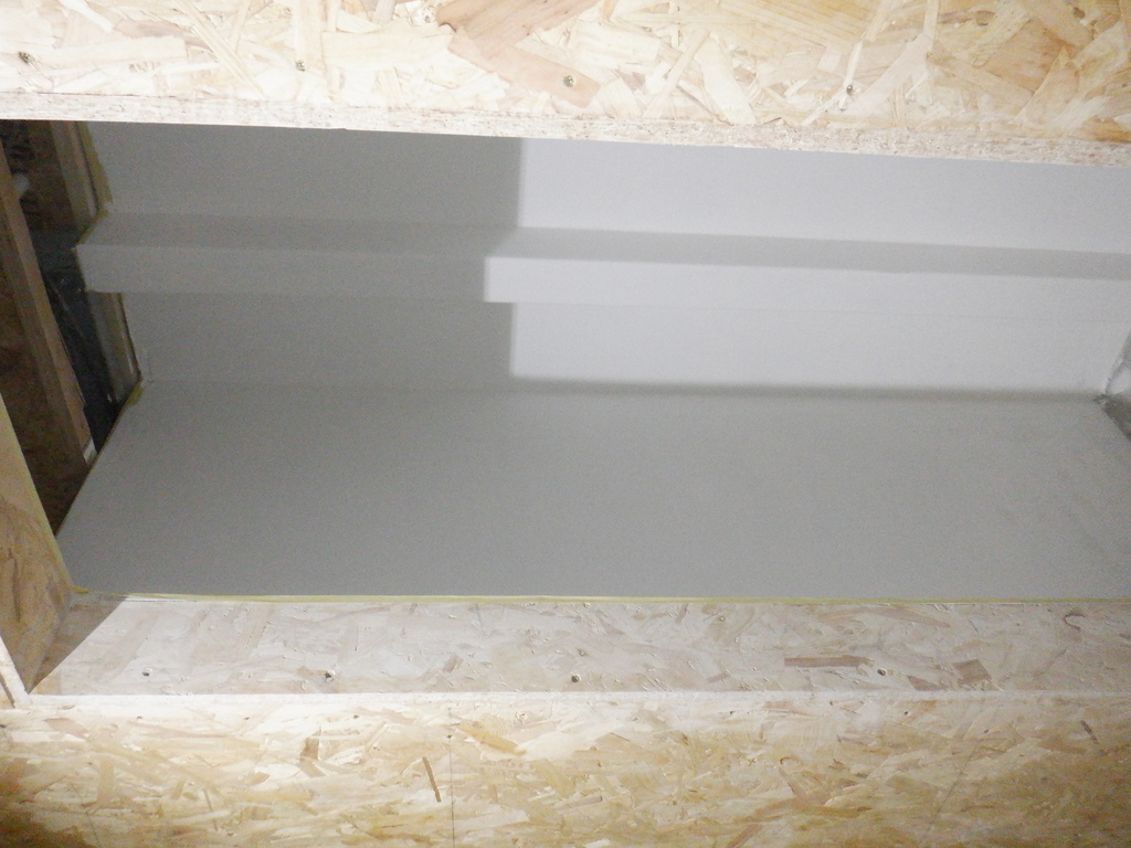
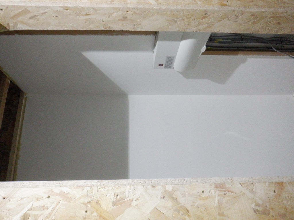
Cloakroom first coat of paint (1)
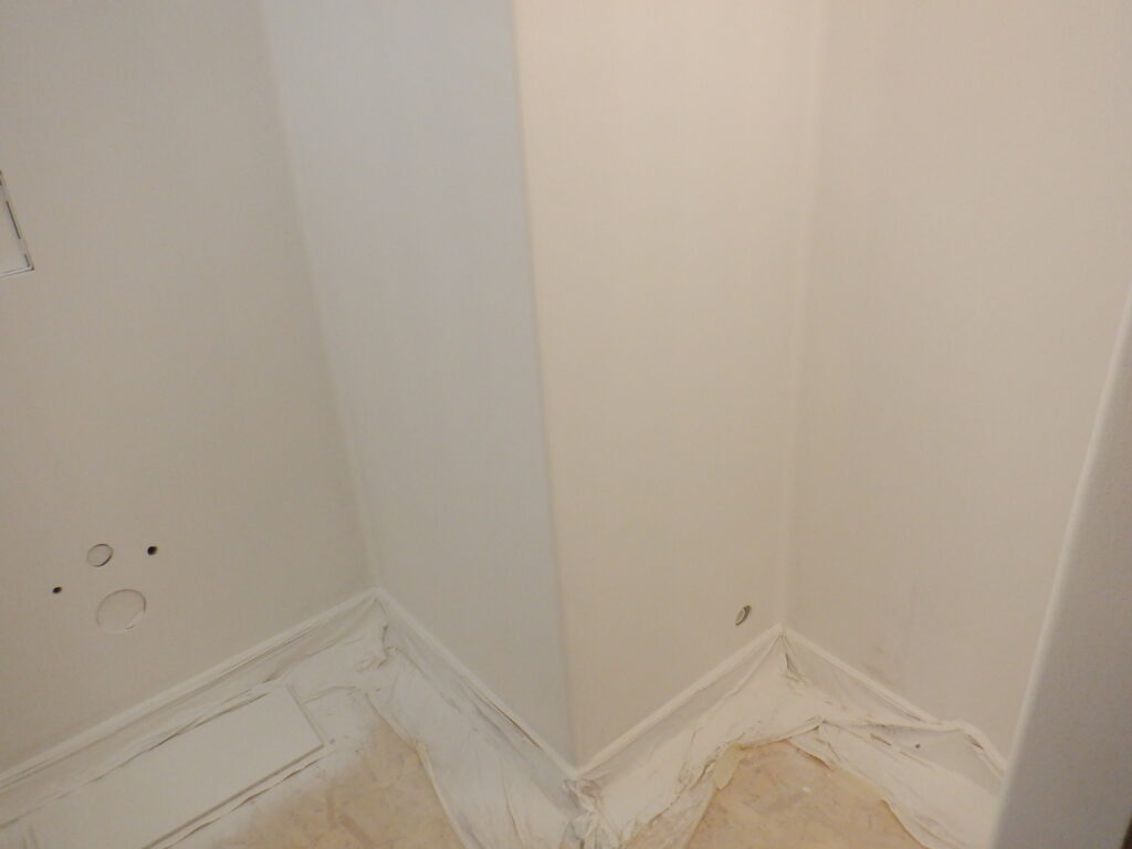
Cloakroom first coat of paint (2)
Cloakroom first coat of paint (3)
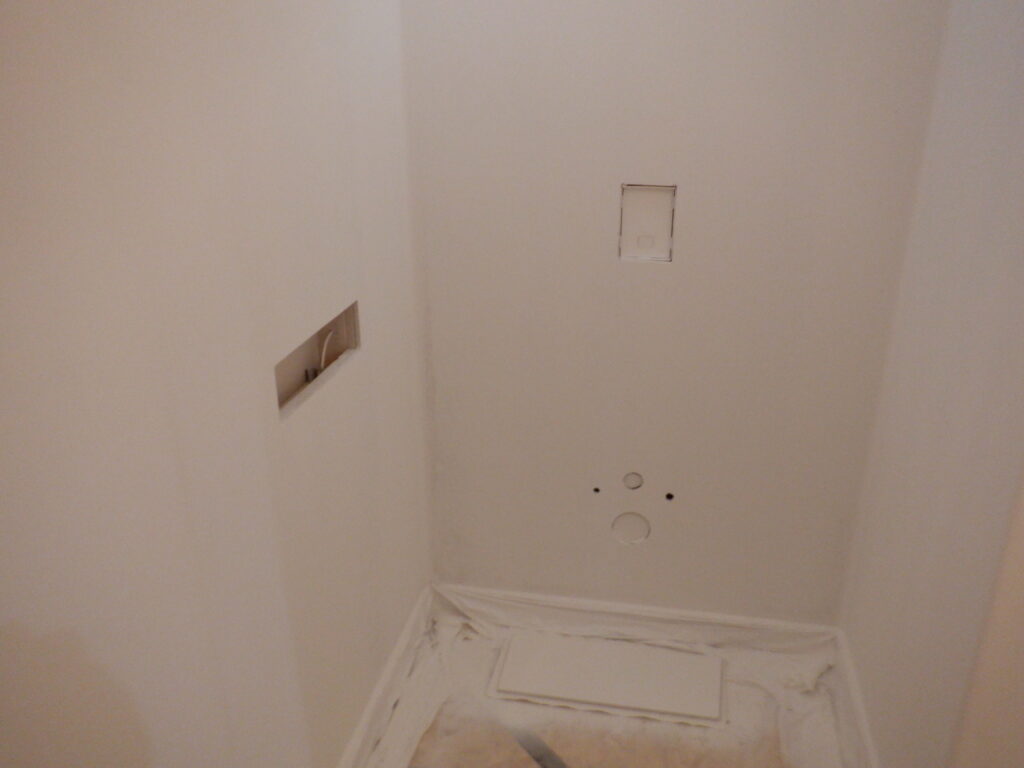
The second coat is now on and we are nearly there. The surfaces is much smoother now, but, we still spotted unfilled holes !! So, we carried on and filled in those little holes and rubbed the surfaces down again smooth.
It is now ready for the final coat of paint and doing the wallpapering. Our next job is to clean and oil the exterior cladding and oak frames.