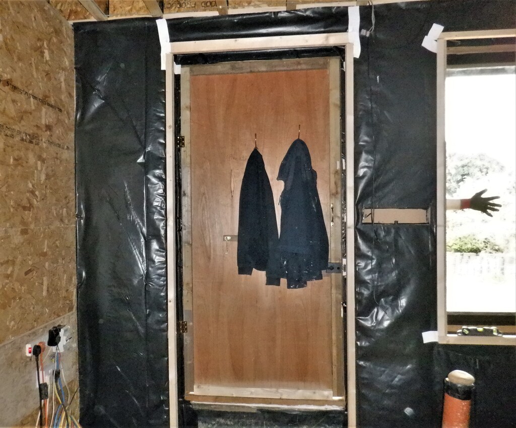
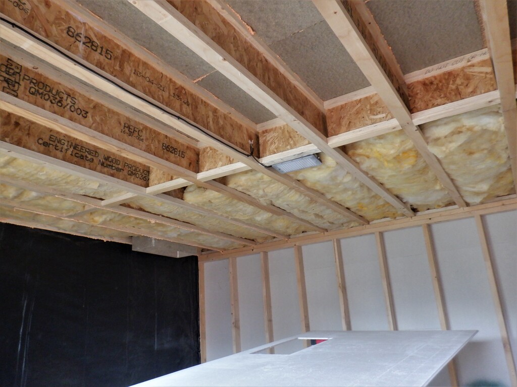
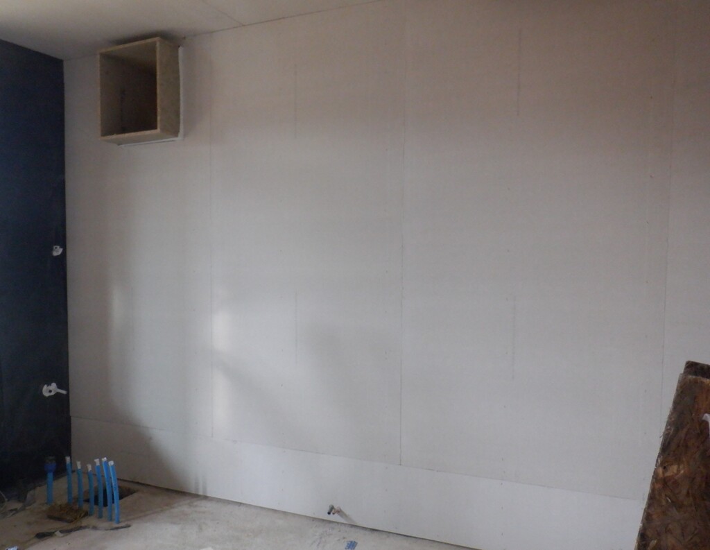
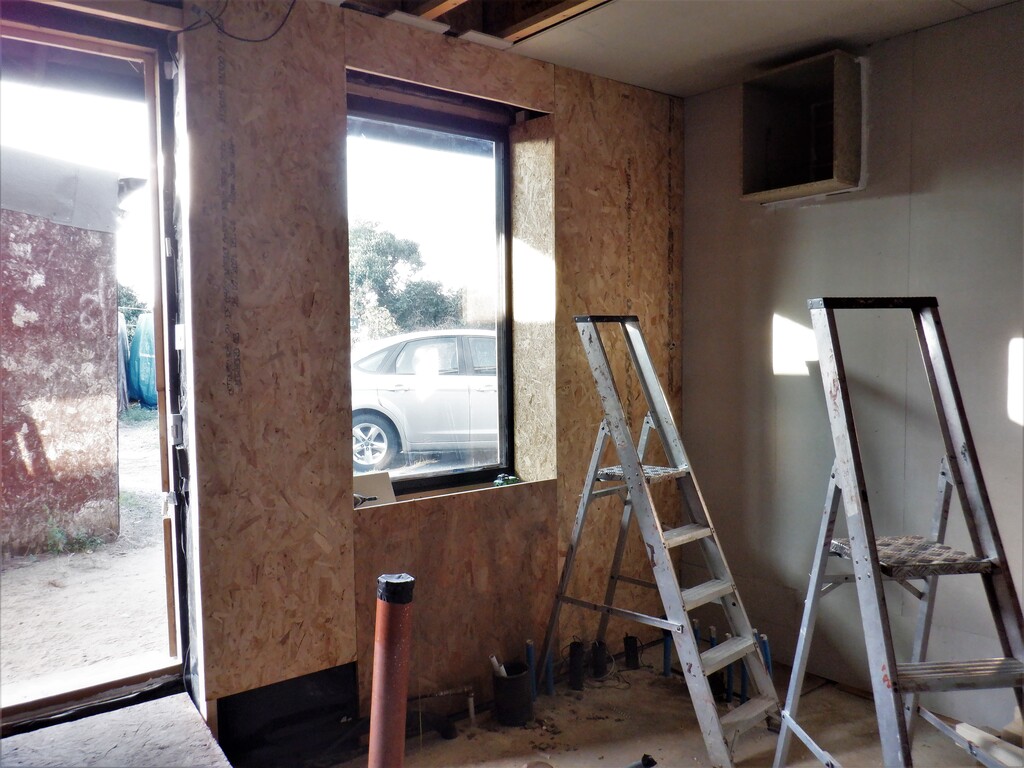
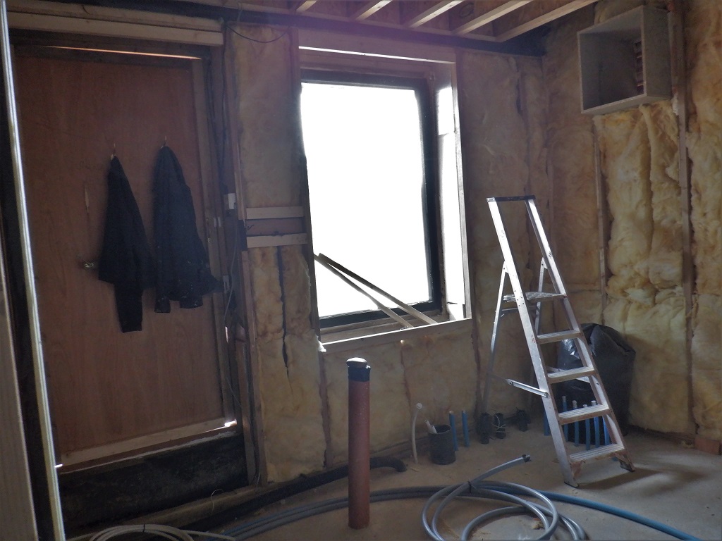
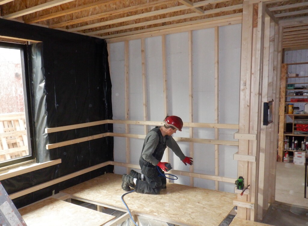
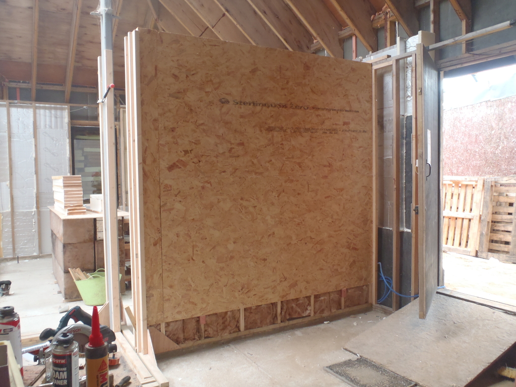
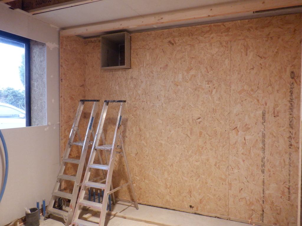
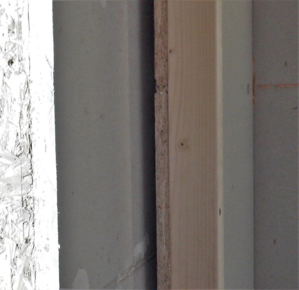
At the beginning of the week, we finished off preparing the Utility Room by concluding the task of putting up OSB wall boards around the door and then trimmed the window .. well we eventually managed it .. slowly! The router bit we had is getting rather blunt so we ordered some more replacement cutters, nice and sharp! Afterwards we extended the height of this wall board layer inside the window area so it goes up to the level of the worktop by using a whole series of biscuit joints around the three edges and sliding in the new piece from above and then fixed in with PU construction glue.
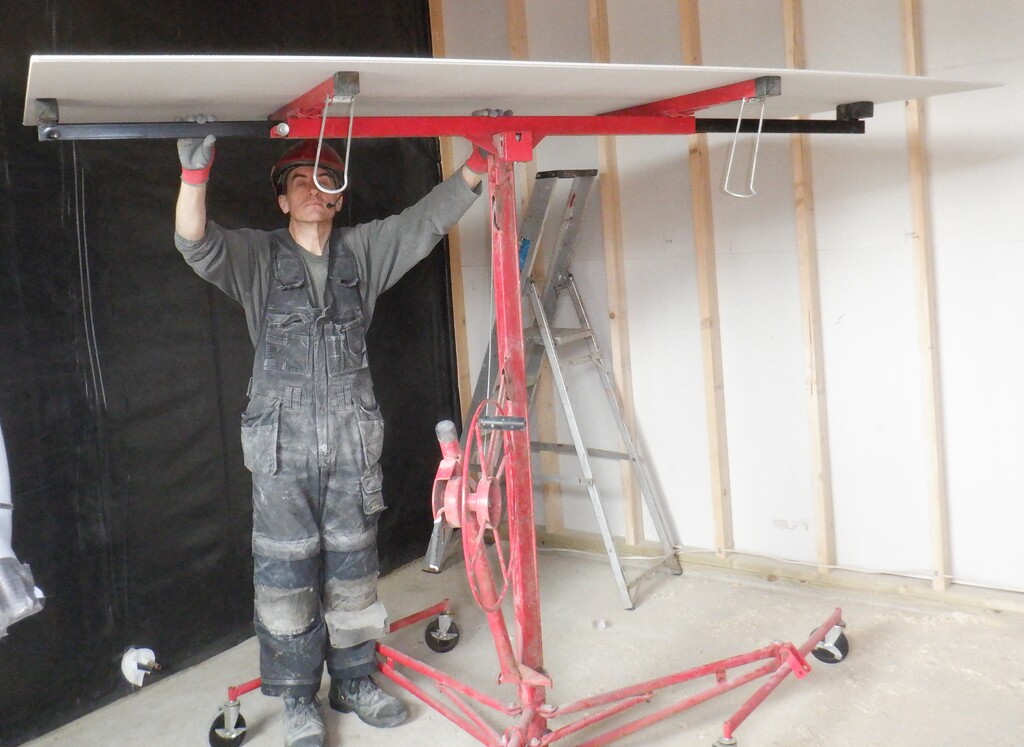
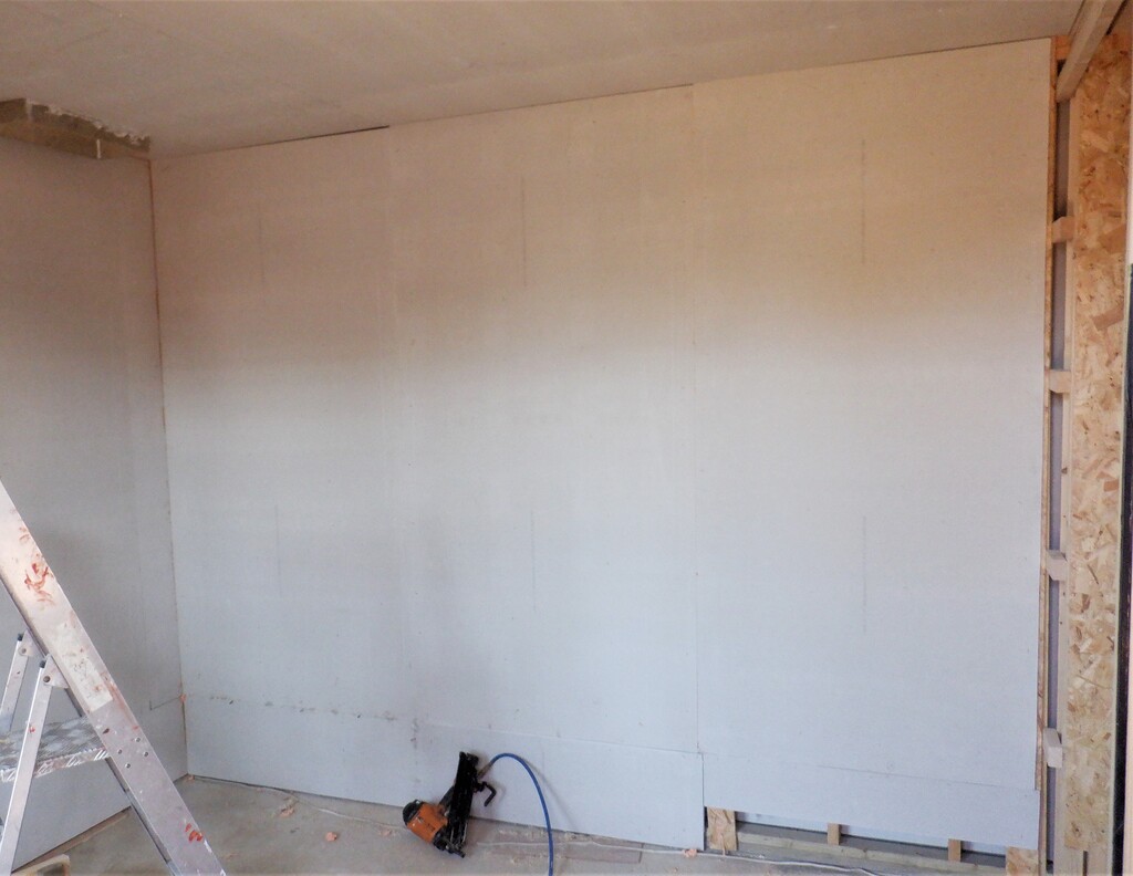
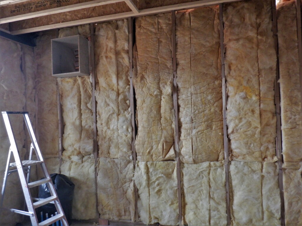
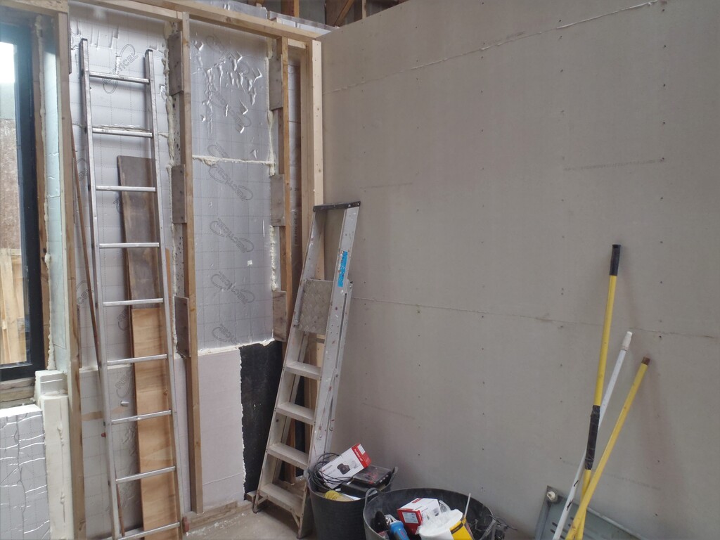
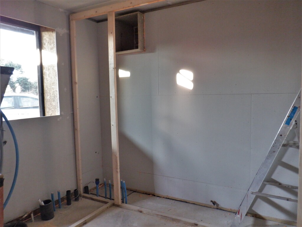
Next, we proceeded to cover all this OSB material with Fermacell boards which was a simple process of spraying lines of PU glue foam all over the surface and then staple each piece up with 25mm long staples fired from our compressed air stapling tool. The joints between pieces were stuck together using the thicker PU construction glue instead, to achieve a tougher and stronger joint.
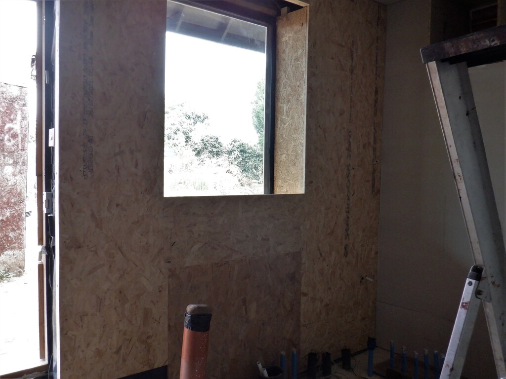
OSB-on-window-wall
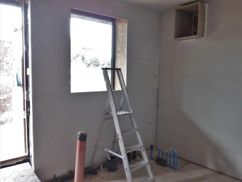
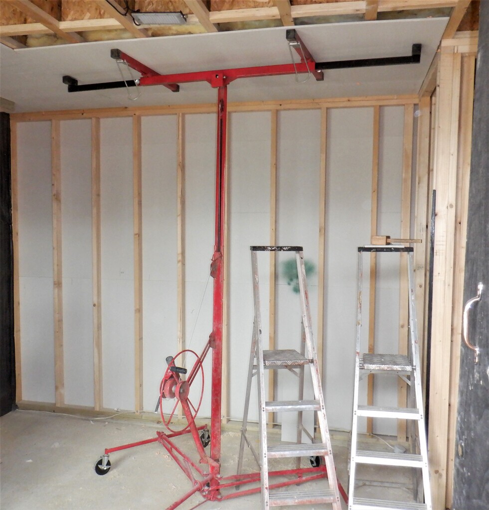
All-walls-have-fermacall-applied
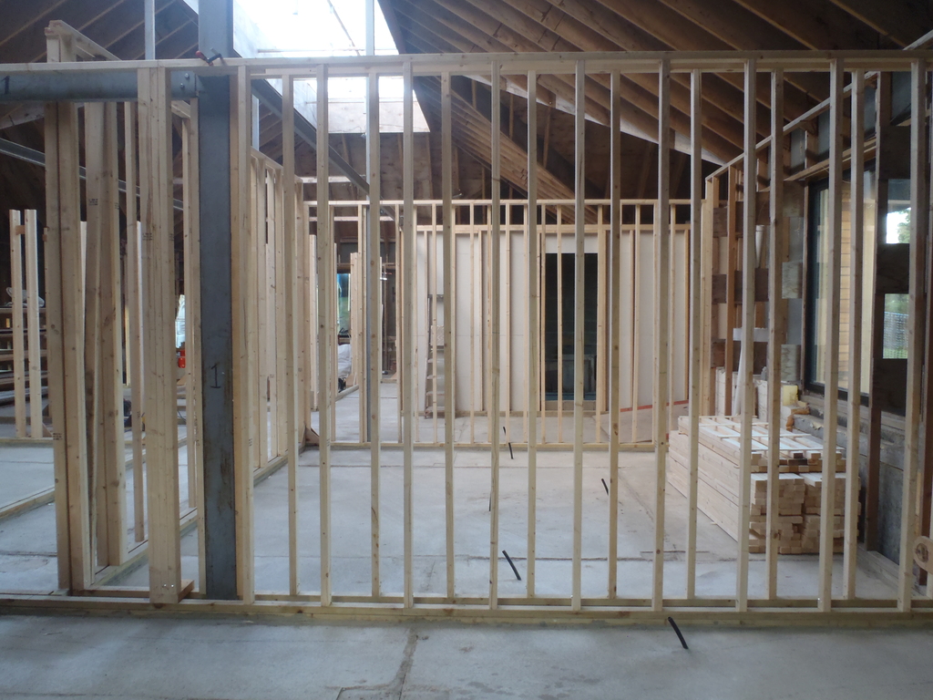
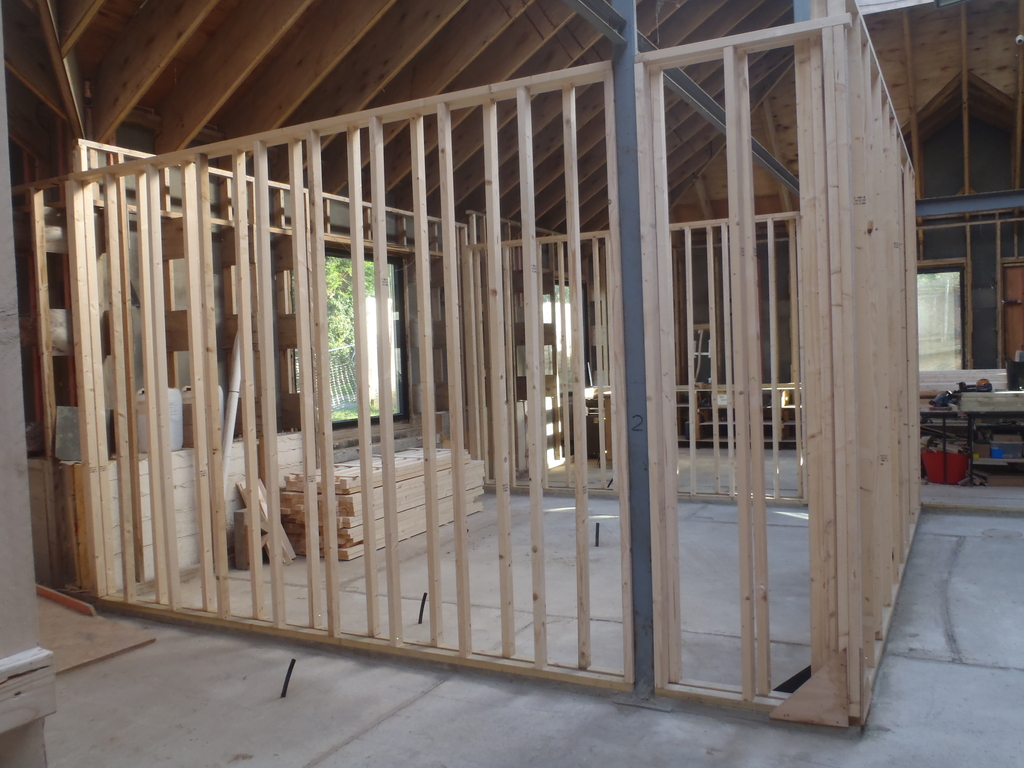
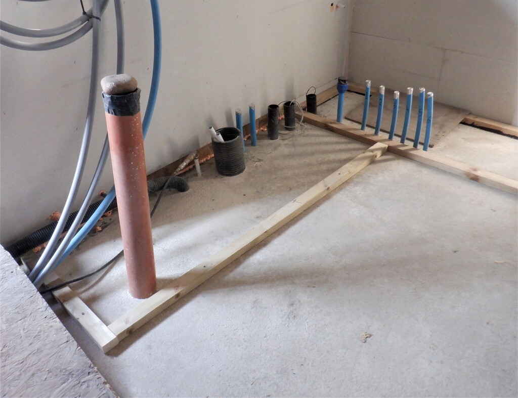
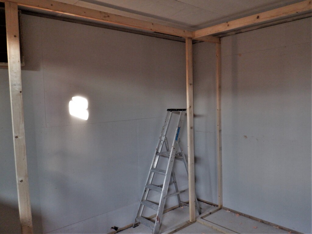
That pretty much concluded the preparation work in getting the basic room done enough so we could start constructing the next object, namely an equipment come machine cupboard to hide away all the various devices, gadgets, mechanisms and storage that will provide the Utilities for the whole house and garage. It is essentially is a room within a room and we are constructing it using thick/heavy materials to try and reduce the noise levels as much as possible and not disturb the rest of the household. So we decided that we would have a cupboard the complete width of the room, from floor to ceiling, along the “E” wall and it will be 600mm overall deep including the wall thicknesses. Part of this design criteria was that we did not want to encroach too closely to the window, to give the window a better look and also we selected 600mm because we didn’t want to have a pile of waste pieces left over when we built the roof out of our 1200mm width sheets. Joining to this basic rectangular shell will be the cupboard region that will hold the clothes drying and vacuum machines, coming along the entertainment wall side of the room and stopping just short of the entrance way to the hall, allowing for the door to open fully and back against the wall. This section is going to be 700mm deep and it turns out to be about 1900mm long, which can be sub-divided into separate modules for each of the machines and other functions like shelving units. This is the extent of what we wanted in creating a noise reducing box like cabinet so we laid down a footprint of treated CLS 63mm timber pieces down on the concrete floor, glued and bolted that defines the outline shape. We also put down extra pieces in front of the window too, to define what would be our worktop and sink section, again being 700mm deep and also being about 1900mm long too.
Cupboard-Footplates-fixed-down-1
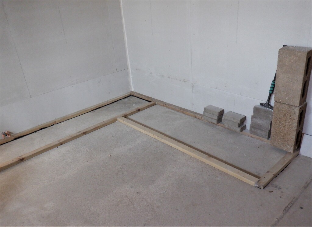
Cupboard-Footplates-fixed-down-2
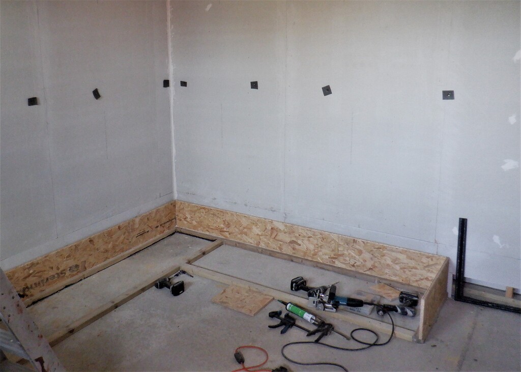
One of the minor tasks we completed before we continued with the cupboard, was to fill in the joints and corners around the fermacell walls with Polyfilla and smooth it all off so it is sealed. After that, we started building the cupboard using 18mm OSB boards but just before that, we stapled up little squares of foam material that is 8mm thick so that we can maintain a air gap between our new cupboard and the room’s walls, to disconnect any direct transmission of any sounds being generated by motors etc. inside the cupboard.
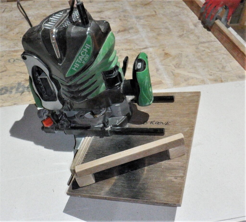
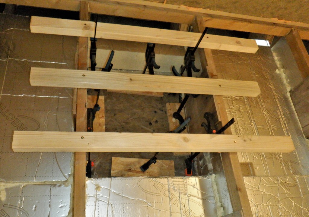
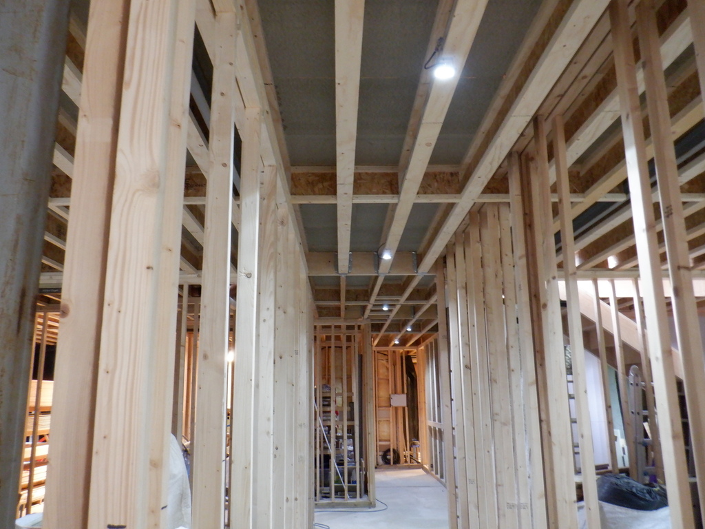
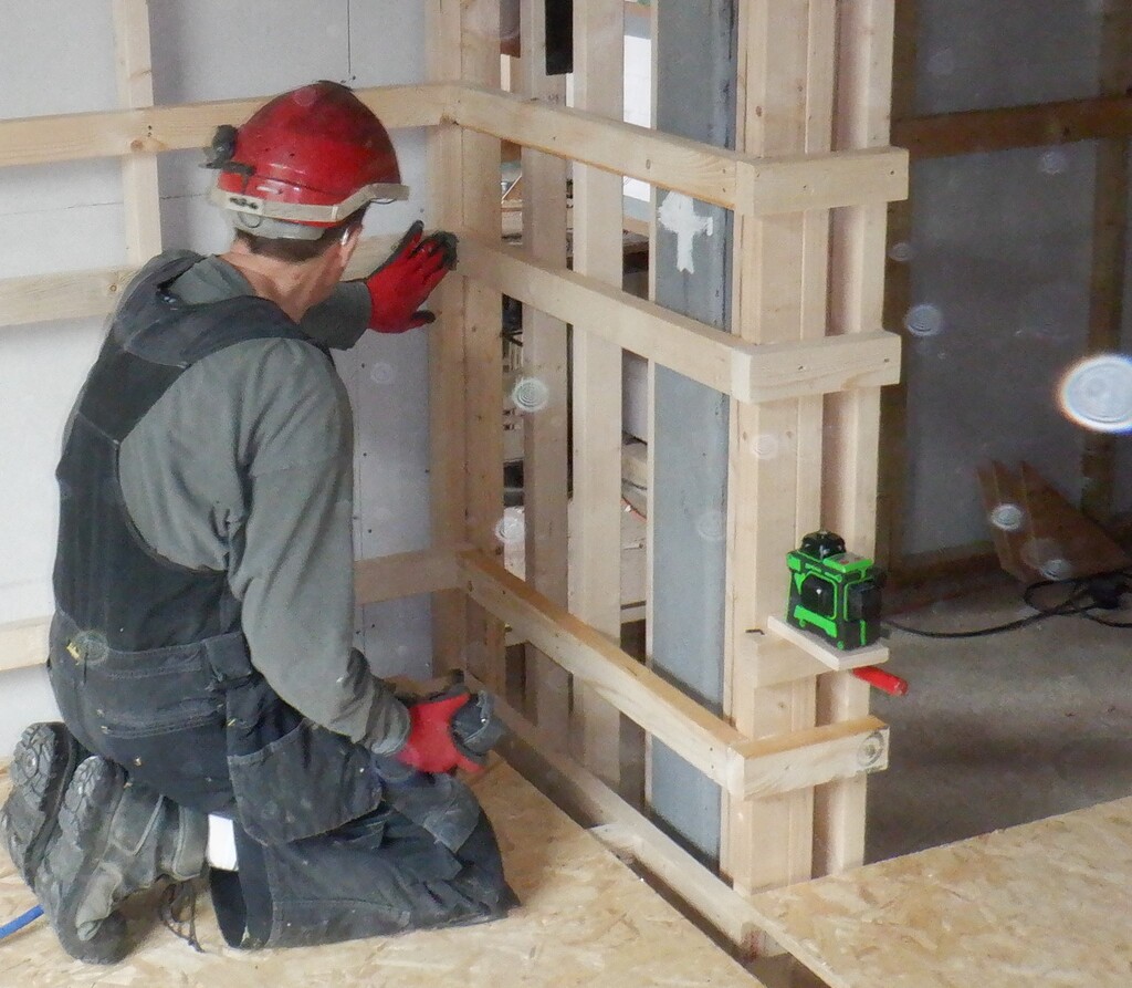
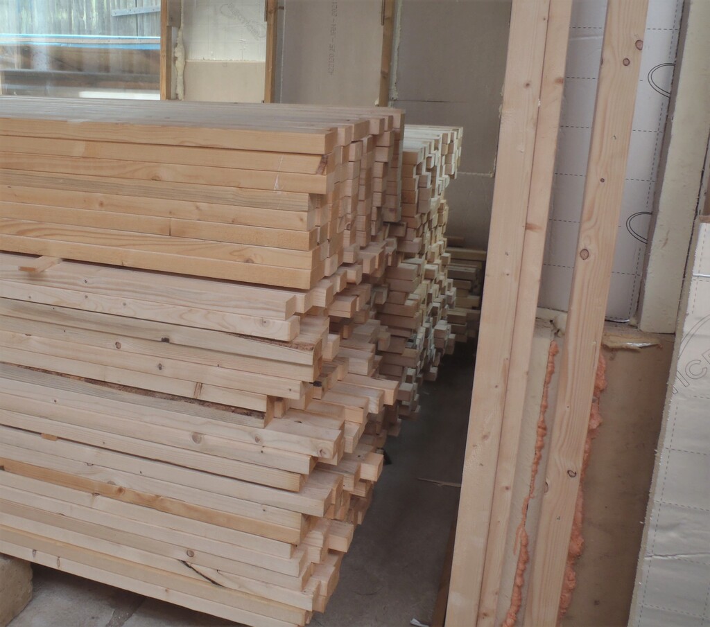
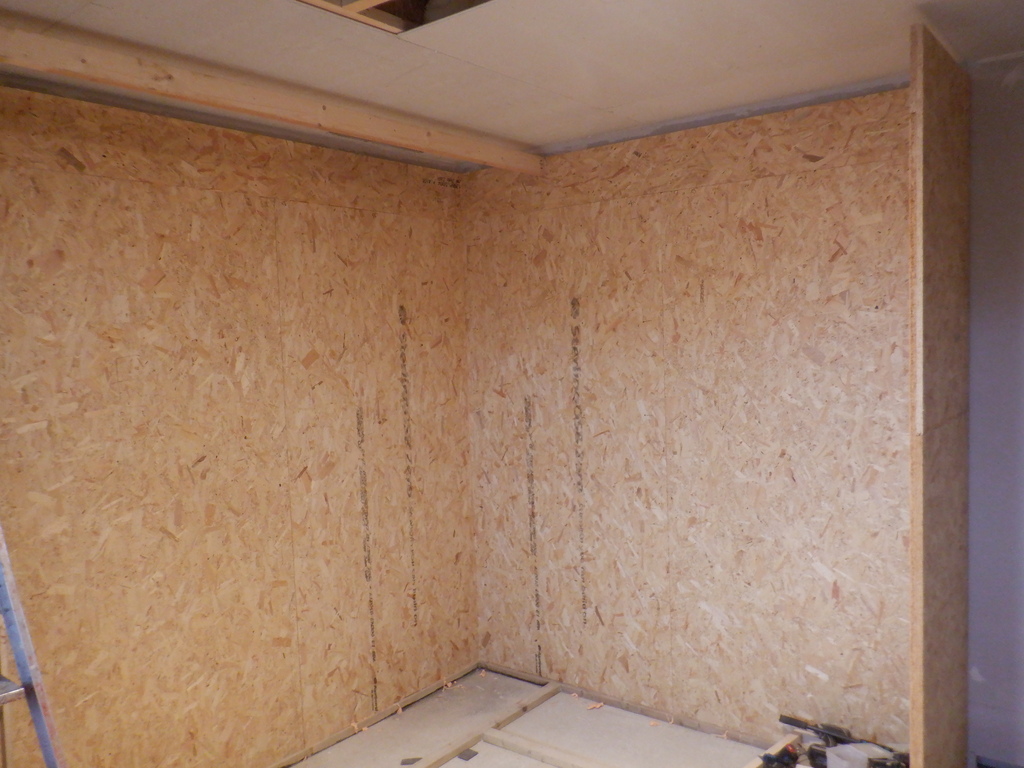
We brought a dozen sheets of 18mm OSB inside from our pile outdoors and got them ready. One thing we wanted to do was to use a tongue and groove joints so they formed a solid structure, a backbone for the rest of the cupboard to be built from. Also, we needed room at the top of these walls to fit a “lid” on top and still be separated from the ceiling, this meant that we needed a full height board (2440mm high) plus a narrow strip of 270mm wide to start at the bottom line sitting on the newly installed CLS footplates. So sliced up two board into eight narrow strips and then cut a set of tongue edging on four of them plus groove edging on the other four.
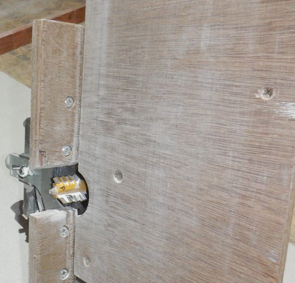
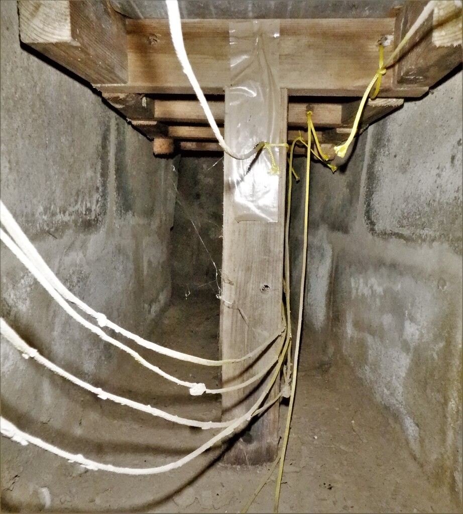
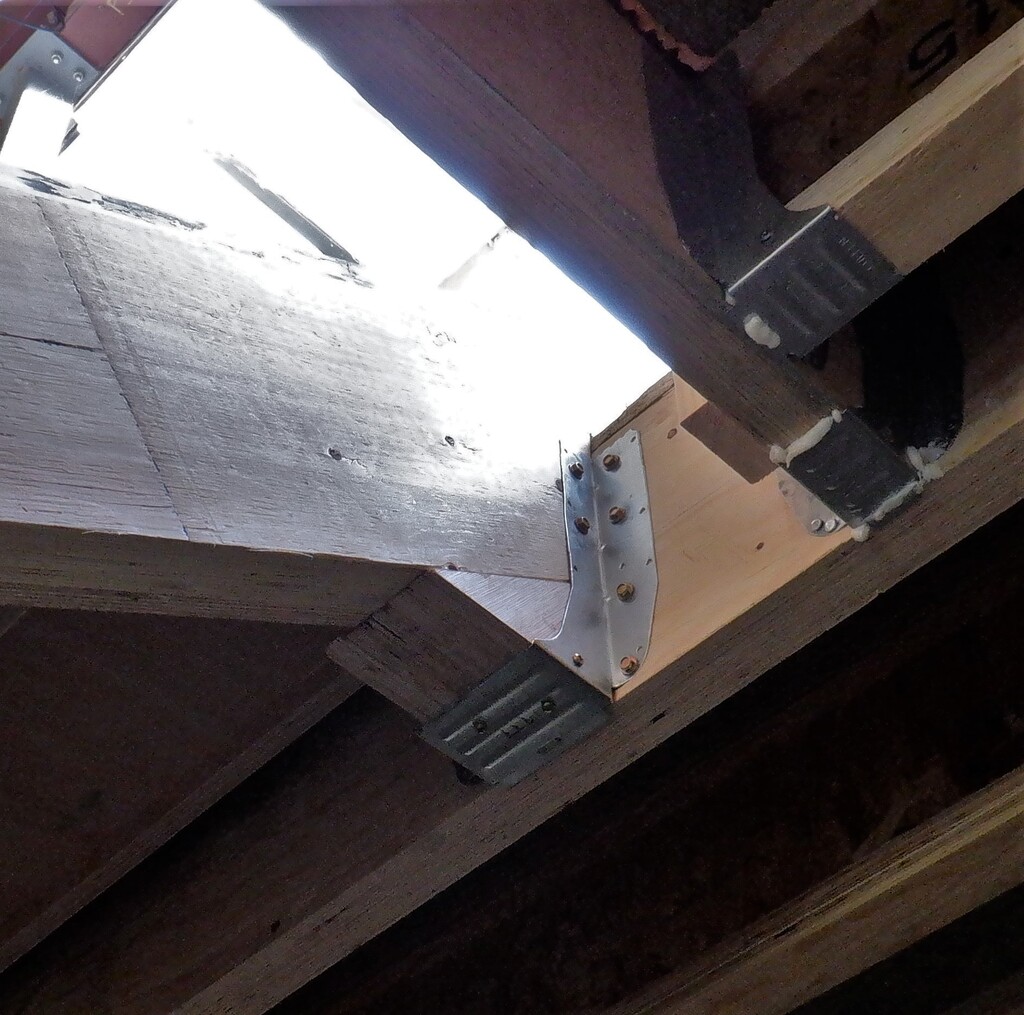
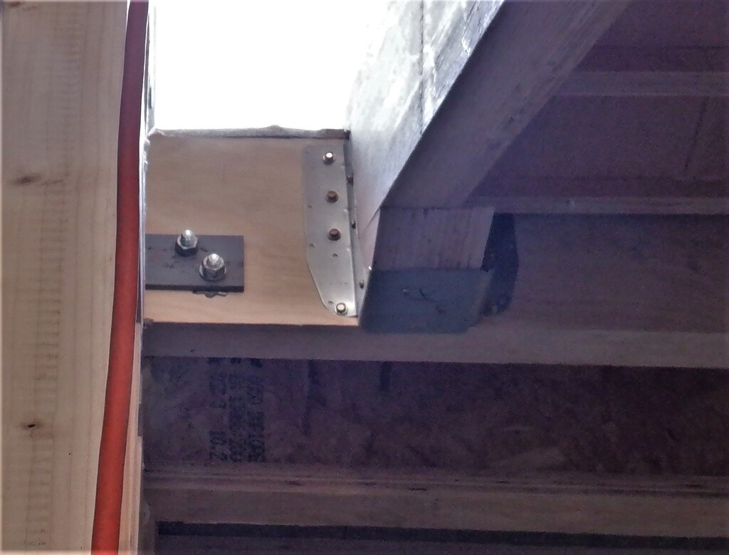
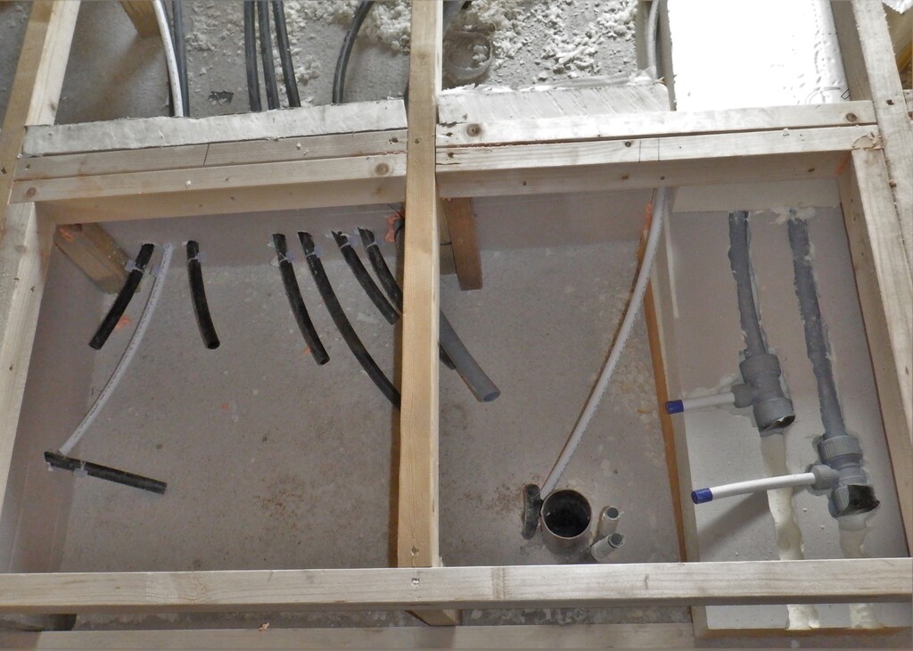
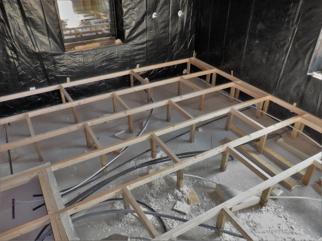
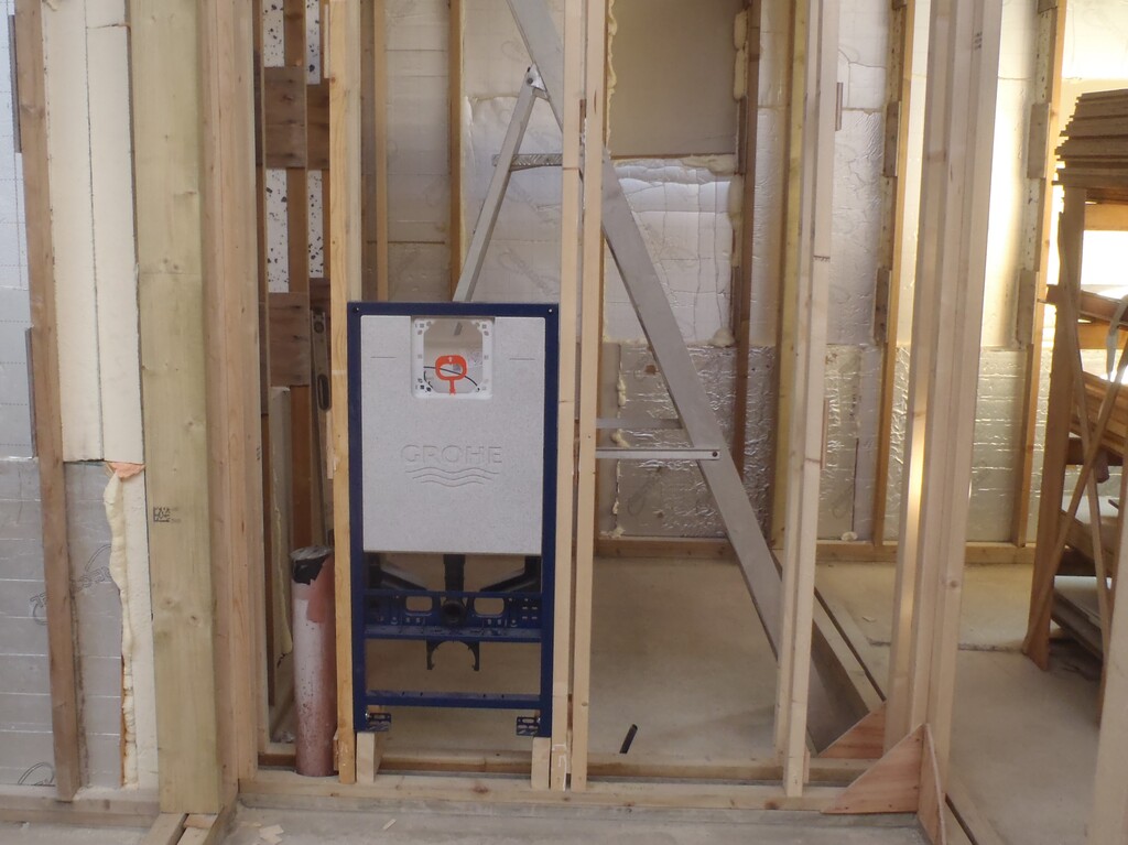
We proceeded with the narrow strip first, right around outer sides of the cupboard and then put a row of horizontally mounted full sized sheets, again with a set of tongue and groove edging. The long side of the cupboard (against the “E” wall) is 3740mm long so we put in a full sheet in the middle and filled in the left and right ends with 650mm pieces. We were making sure that no joints lined up with each other and creating a stronger monolithic backbone. The top line of OSB board had to have a large section cut out to make way for the air ducting sticking through the wall. Oh yes, the same for the five other sticking out conduits and pipes at various places and also we had unscrewed and lifted the air duct that is coming down through the ceiling.
we ended up with the first layer all done, starting about 300mm from the window, coming along the “E” wall some 3.7metres and turning along the entertainment wall another 2.5metres before finally turning right angled from the main wall to form the end of the cupboard which is a further 750mm wide.
First-row-of-OSB-for-cupboard
That took a while to do because of all the tongue and groove edges we needed to cut and fit everything together with glue etc. but once we have done that first layer, we could mount on the second layer much faster because we didn’t need to do any further tongues or grooves again as we had the backbone layer to press against, keeping the joints neat and tidy. We proceeded to spray a zigzag line of PU glue foam all over the surface and screwed this second layer straight on to the first layer. We had drilled clearance holes all over the sheet, we did a grid of four rows by six columns, giving us a total of 24 screws to tighten the two sheet together squeezing the glue out thinly. We used about 200 screws by the time we done all the second layer!
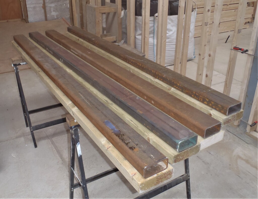
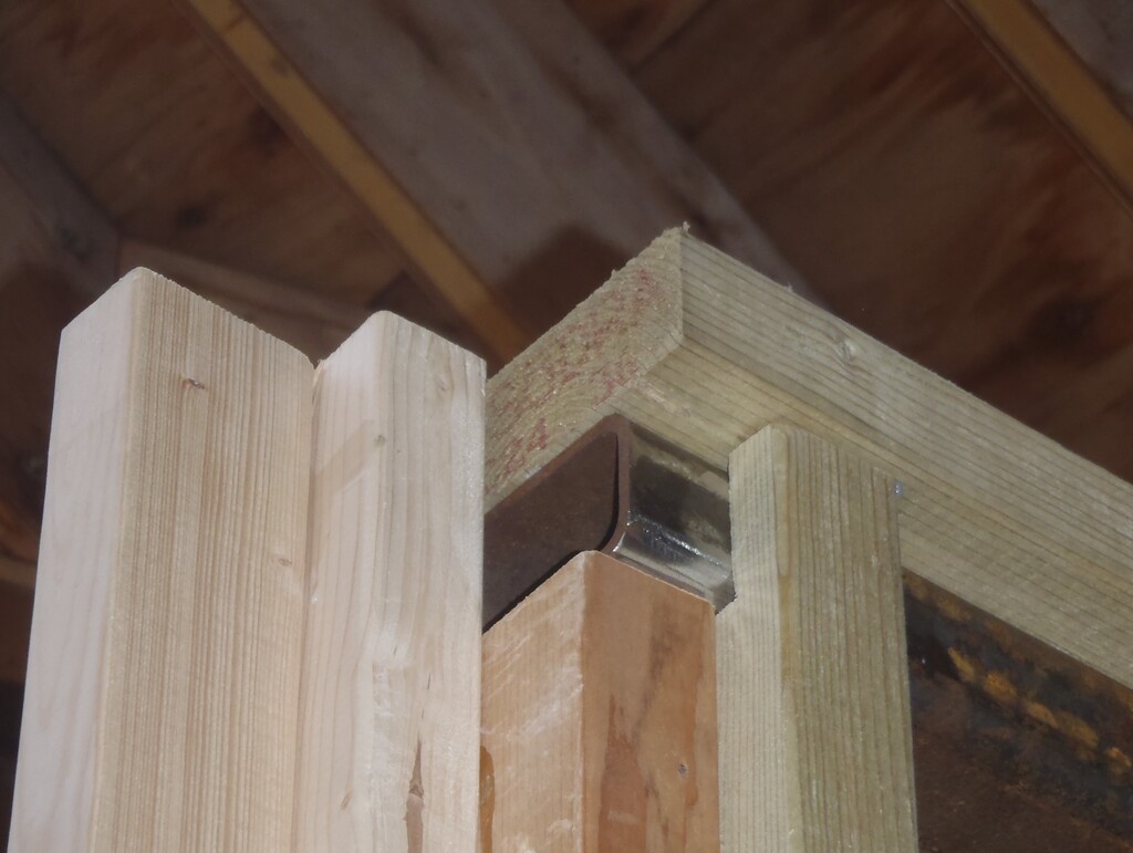
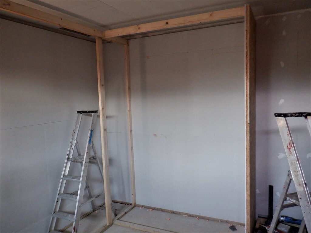
Next, we put up a solid CLS 89mm piece of timber right across to form a lintel for the front of the cupboard to help support the heavy “lid” which will be made of three layers of fermacell sheets.
All-cupboard-OSB-placed-and-glued-1
All-cupboard-OSB-placed-and-glued-2
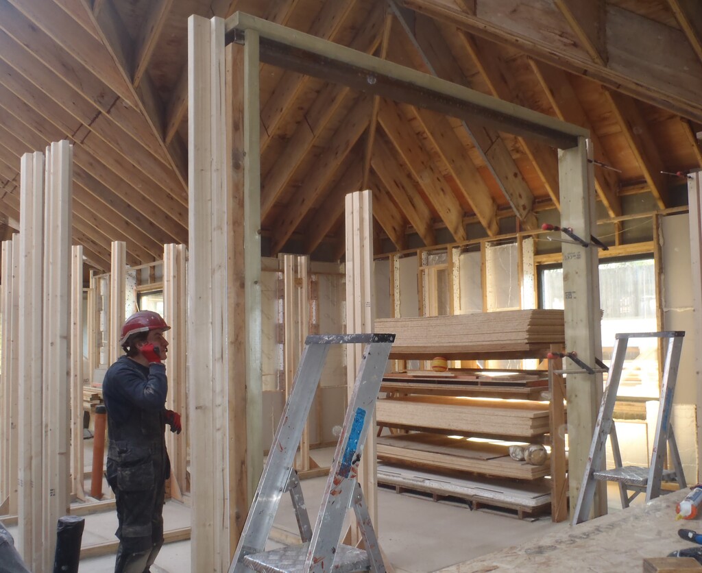
On our last day, we went around fitting in a third layer of material, this time our fermacell “plasterboard” sheets, again, just went straight up onto the wall surface with the PU foam glue and this time, was stapled on with 25mm staples. It didn’t take very long and we finished off the day by putting four vertical CLS posts, two 63mm ones up against the walls under the lintel, and the other two being 89mm pieces, again fitted under the lintel but this time 800mm out from the walls. All four will help support the lintel and in turn, the roof of the cupboard. The last piece of CLS, another shorter 89mm piece, went along the front of the side arm of the cupboard, also to support the heavy “lid” over this side section of cupboard.
Cupboard-lined-and-basic-framework-errected-1
Cupboard-lined-and-basic-framework-errected-2
Cupboard-lined-and-basic-framework-errected-3
The-whole-cupboard-is-isolated-from-the-wall-of-the-room
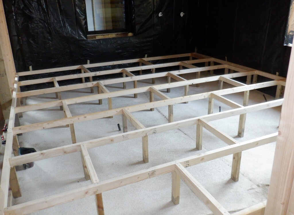
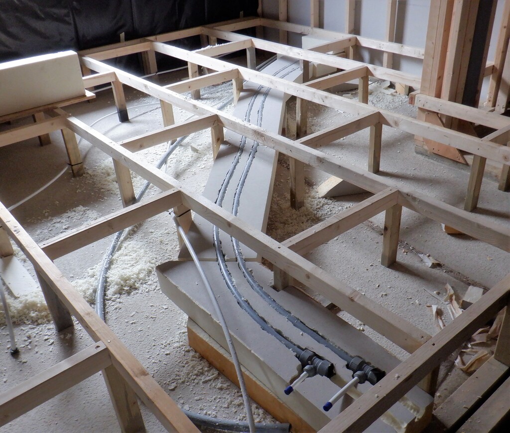
Next week, we will start building the lower sections of the front parts of the cupboard, up to the floor levels and getting ready for the flooring supports for the room and starting to lay out the pipework and ducting etc. going across the room and out into the hallway.