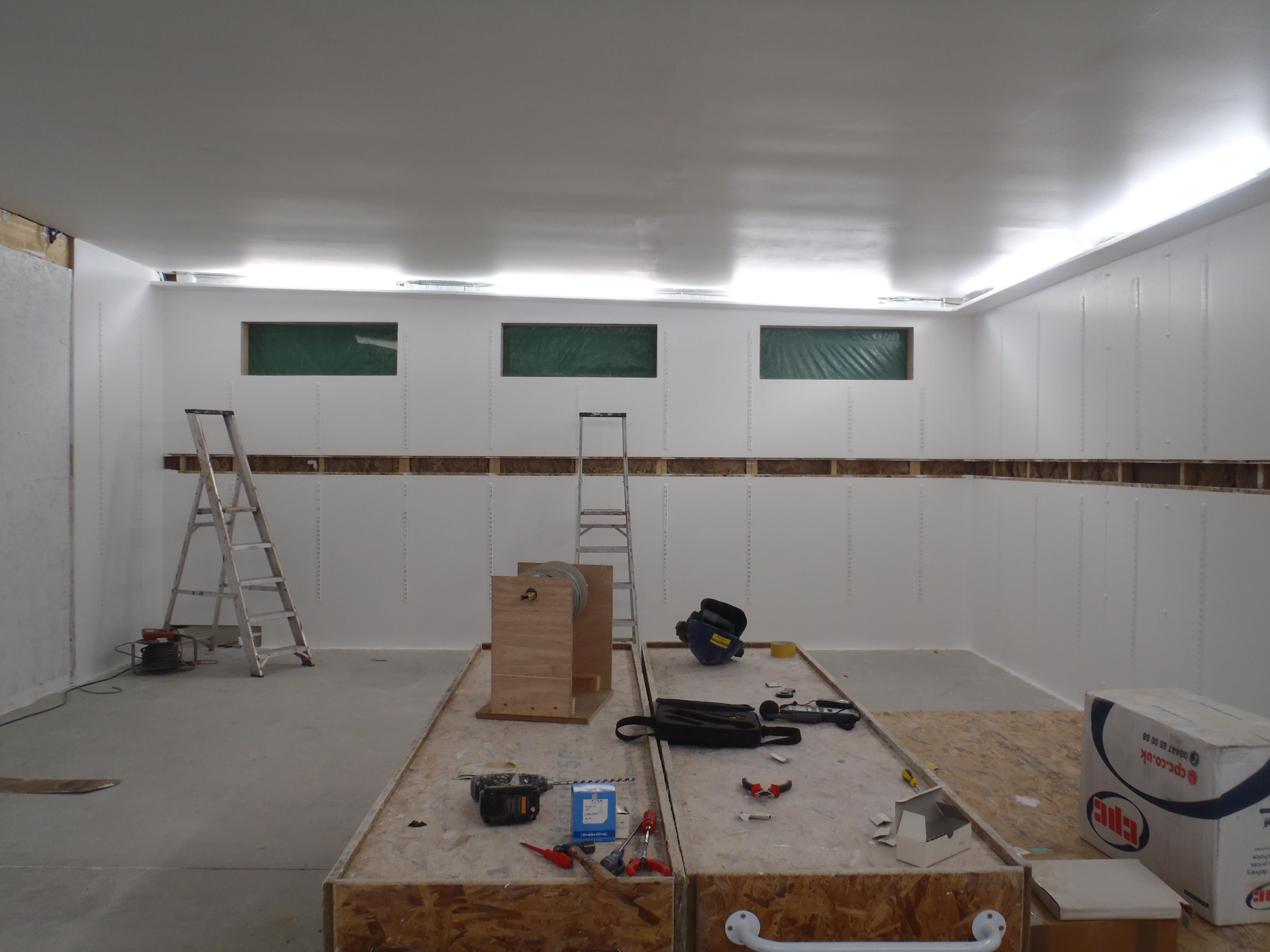
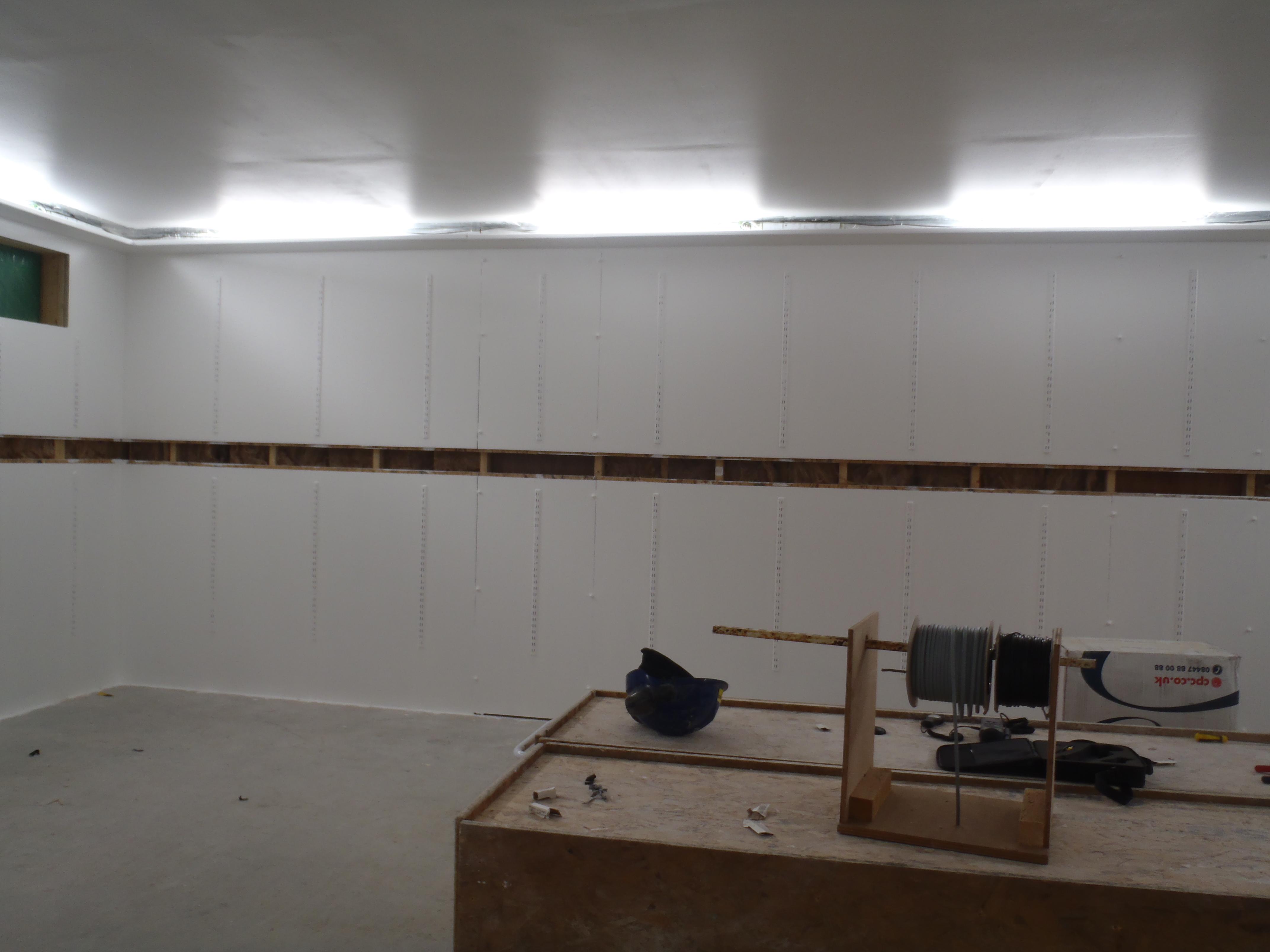
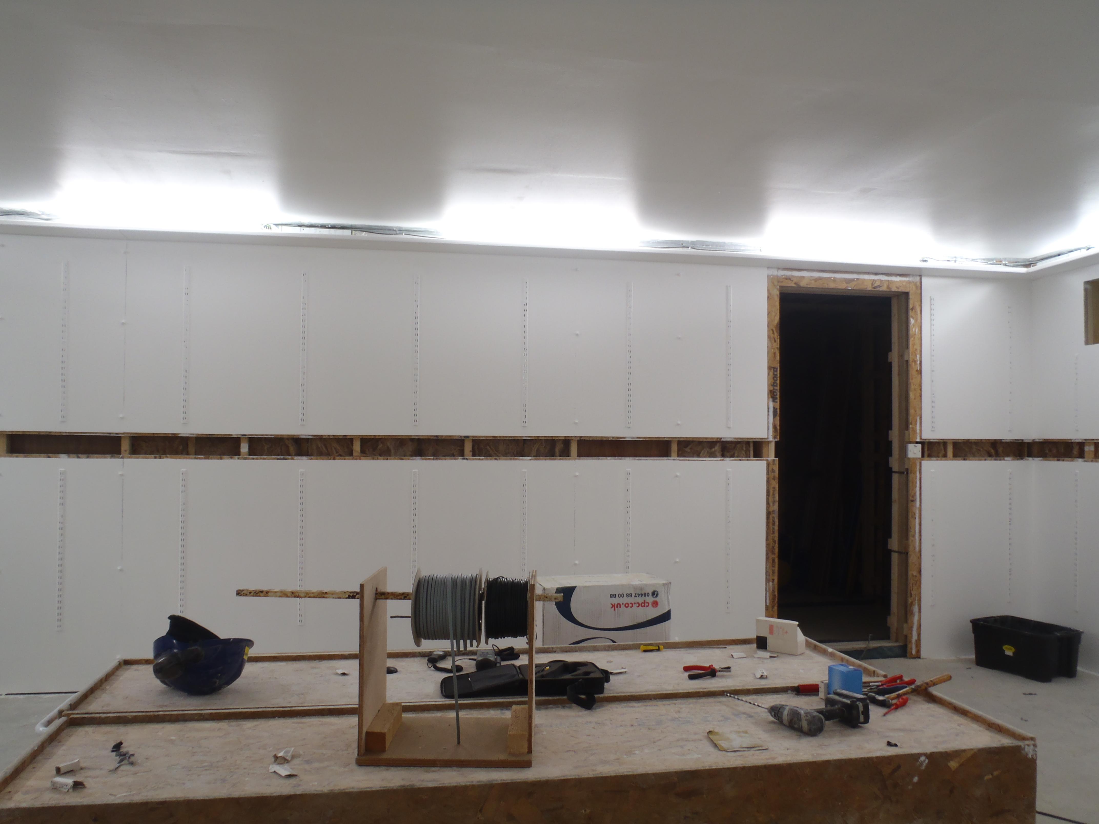
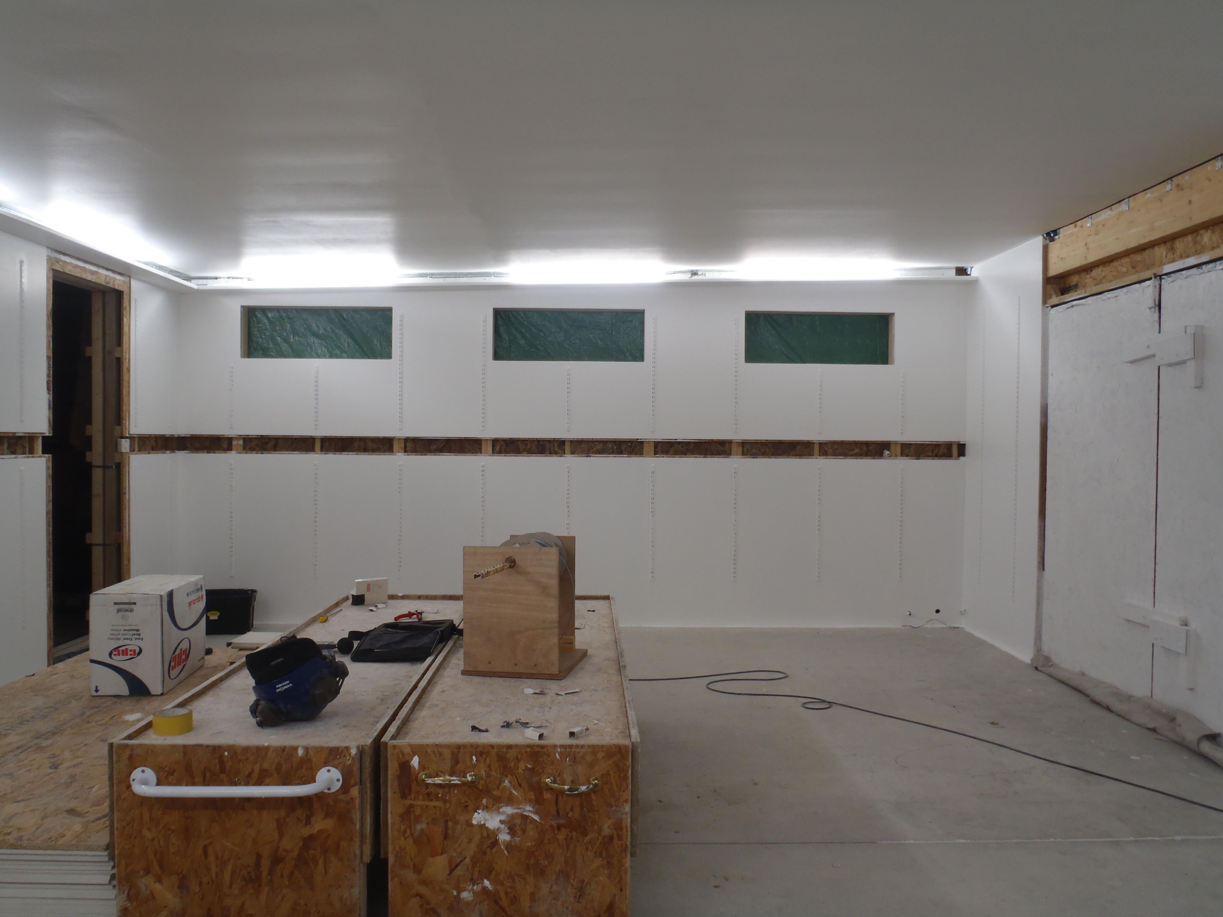
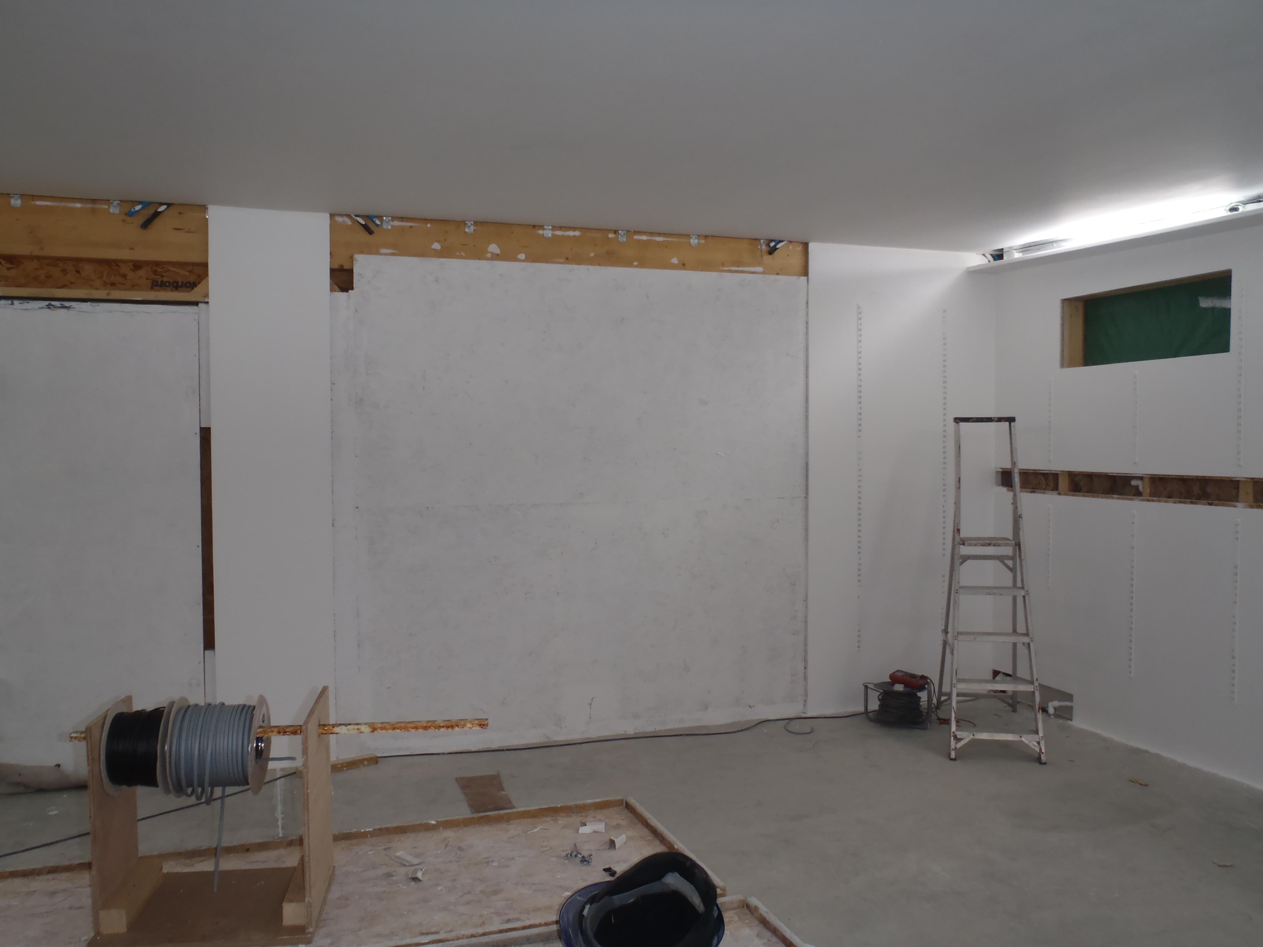
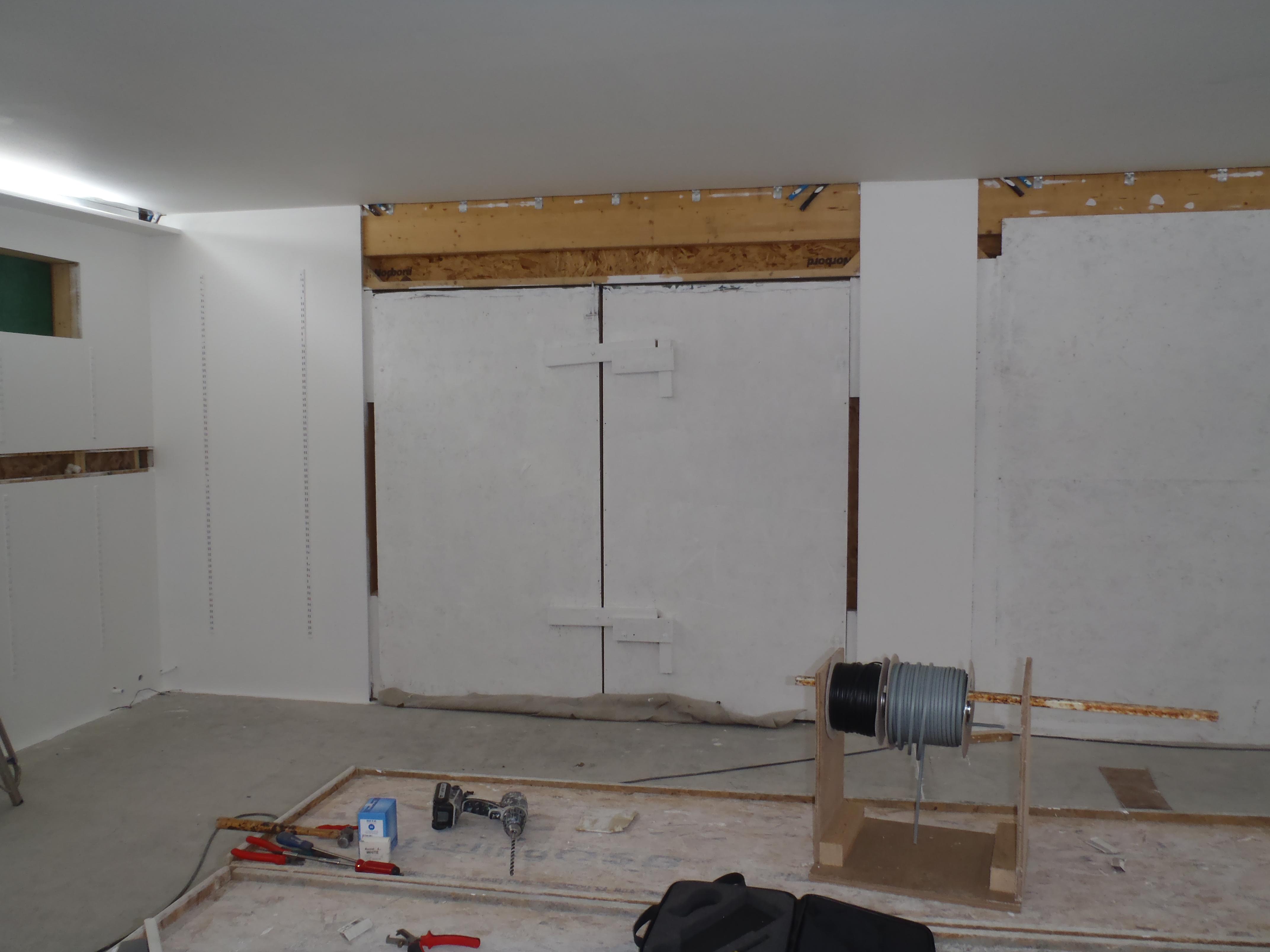
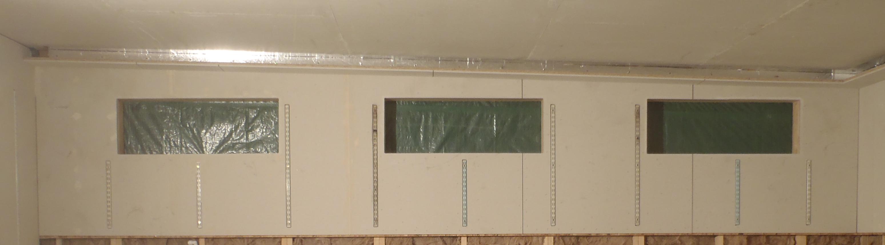
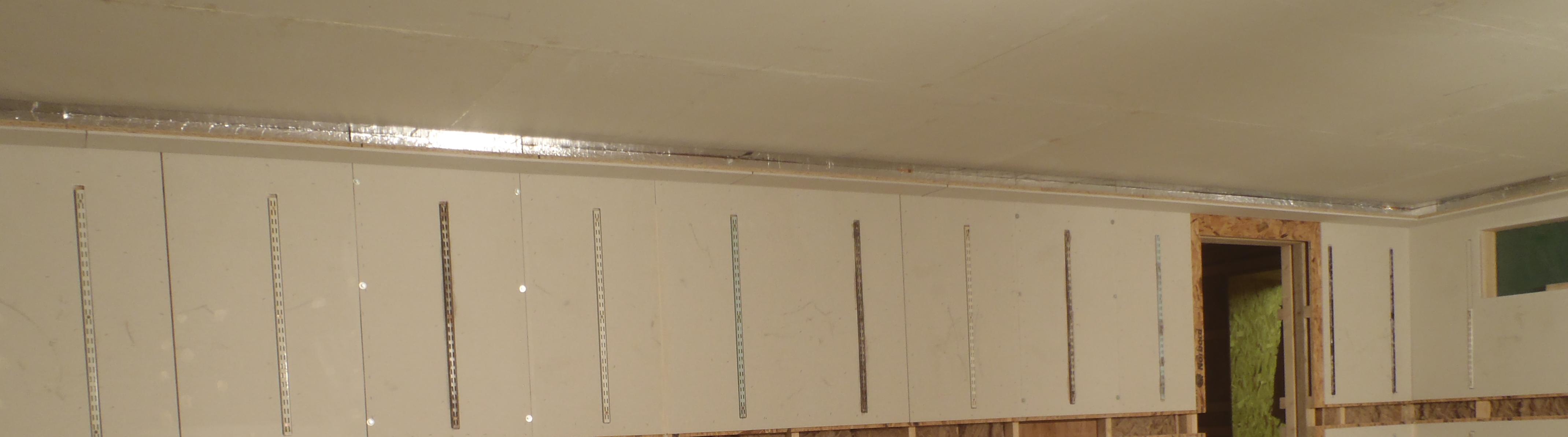
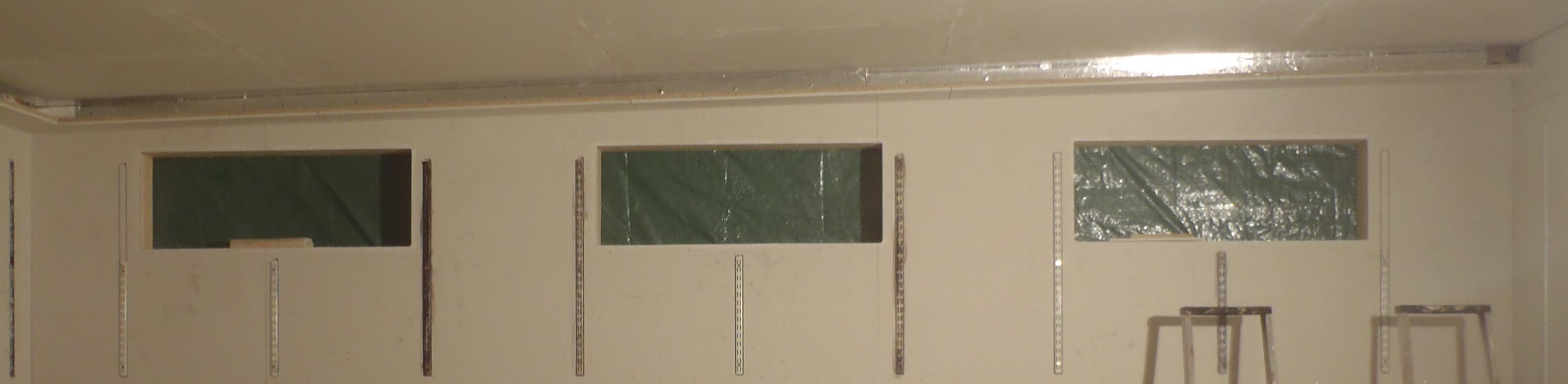
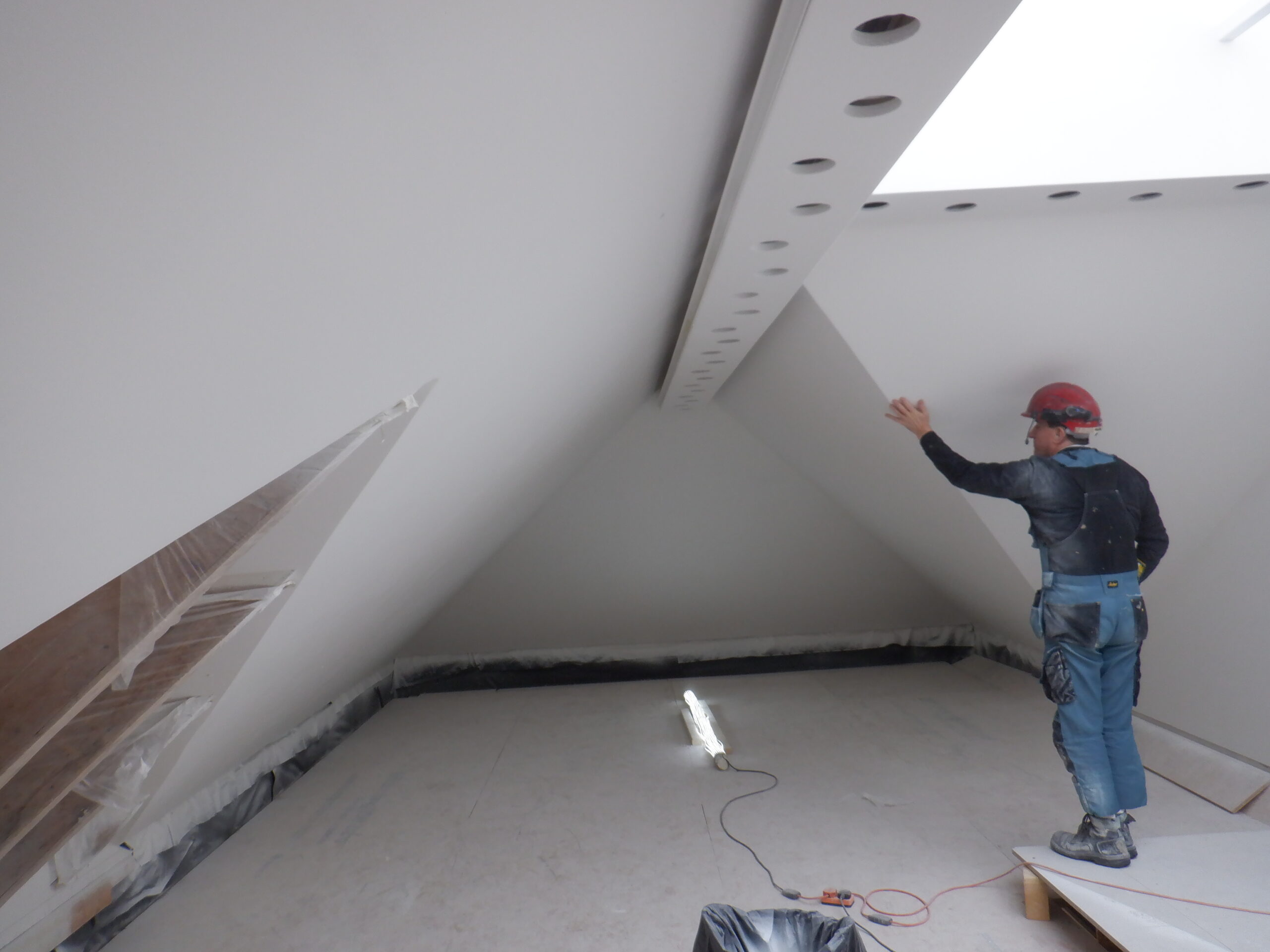
Since we had finished the Skylight and didn’t need the use of the mobile platform anymore, we constructed the remaining wall framework in the middle of the Gallery, between the metal legs that are holding up the Skylight. We put in two more “gaps” for 600mm wide shelving units and cupboards, alongside a standard 800mm wide doorway that gives access to the First Floor room beyond. The wall surface was built up to match the rest of the wall that goes past the Gallery and down to the Great Room, forming an internal gable divider to the rest of the house.
In the meantime, the fermacell boards that got put up before Christmas, had all their joints thoroughly sanded using our trusty old belt sander with a base plate fitted that allowed us to remove any slight ridges formed between sheets. We decided that because we had a solid OSB backing layer all over the ceiling, we didn’t have to “Tongue and Groove” the thin 10mm thick edges of the fermacell boards, only relying on the PU construction glue in the joints to hold everything tight together. This meant that there were a very slight variations in how flat we managed to staple up each sheet and the joints had a tiny steps in them. So, we came along with our belt sander and using a 40grit belt, went around “ironing” these steps and smoothed out the whole surface.
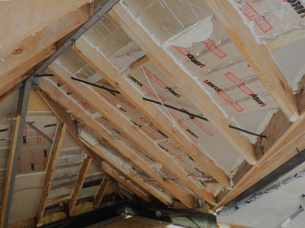
The Dorma section was similarly done but had to be done by hand as the machine was too large to fit inside among the rafters!
As that was happening, the staple holes and the now smooth joints were filled with good quality decorators filler. The initial wall, the “A” section, was done using a standard spatula tool but then had the idea of using a piping bag so we raided mum’s baking supplies for those disposable plastic bags and nozzles! It was a very good idea as we could squirt in the filler into the staple holes, after we had blasted them out using our compressed air, and leave a little sausage of filler proud on top, to allow shrinkage. On the first section we were doing, using the spatula, discovered that the fermacell plasterboards were so absorbent that they sucked the water content out of the filler hence shrinking it down in the holes, causing us to repeat the filling again. But, using the piping bags, it was much much better, in both time and efficient use of the filler.
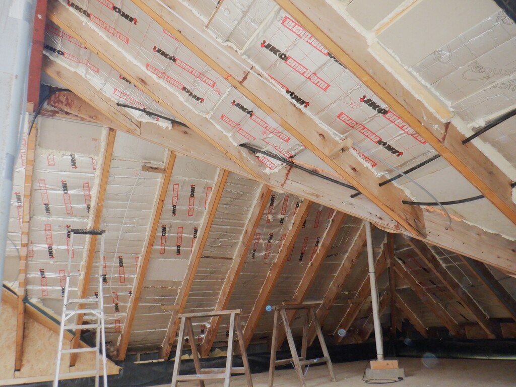
A roof of blobs
P Roof filler dots
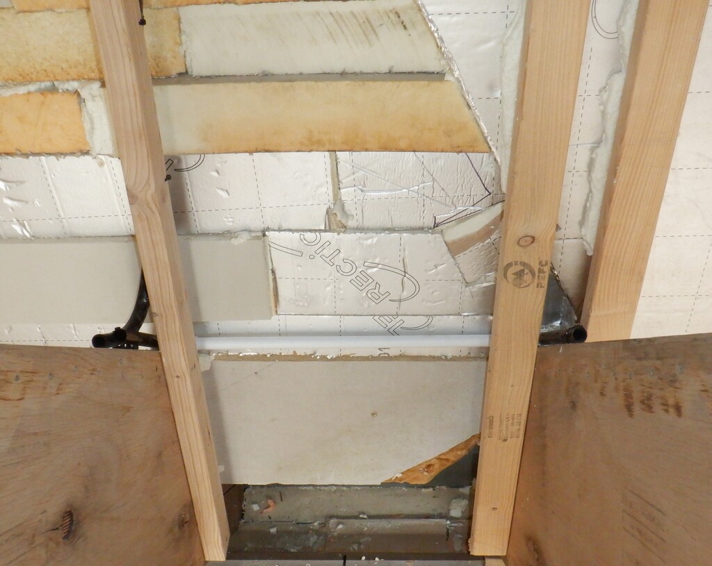
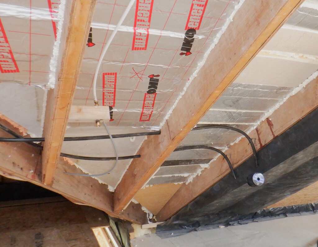
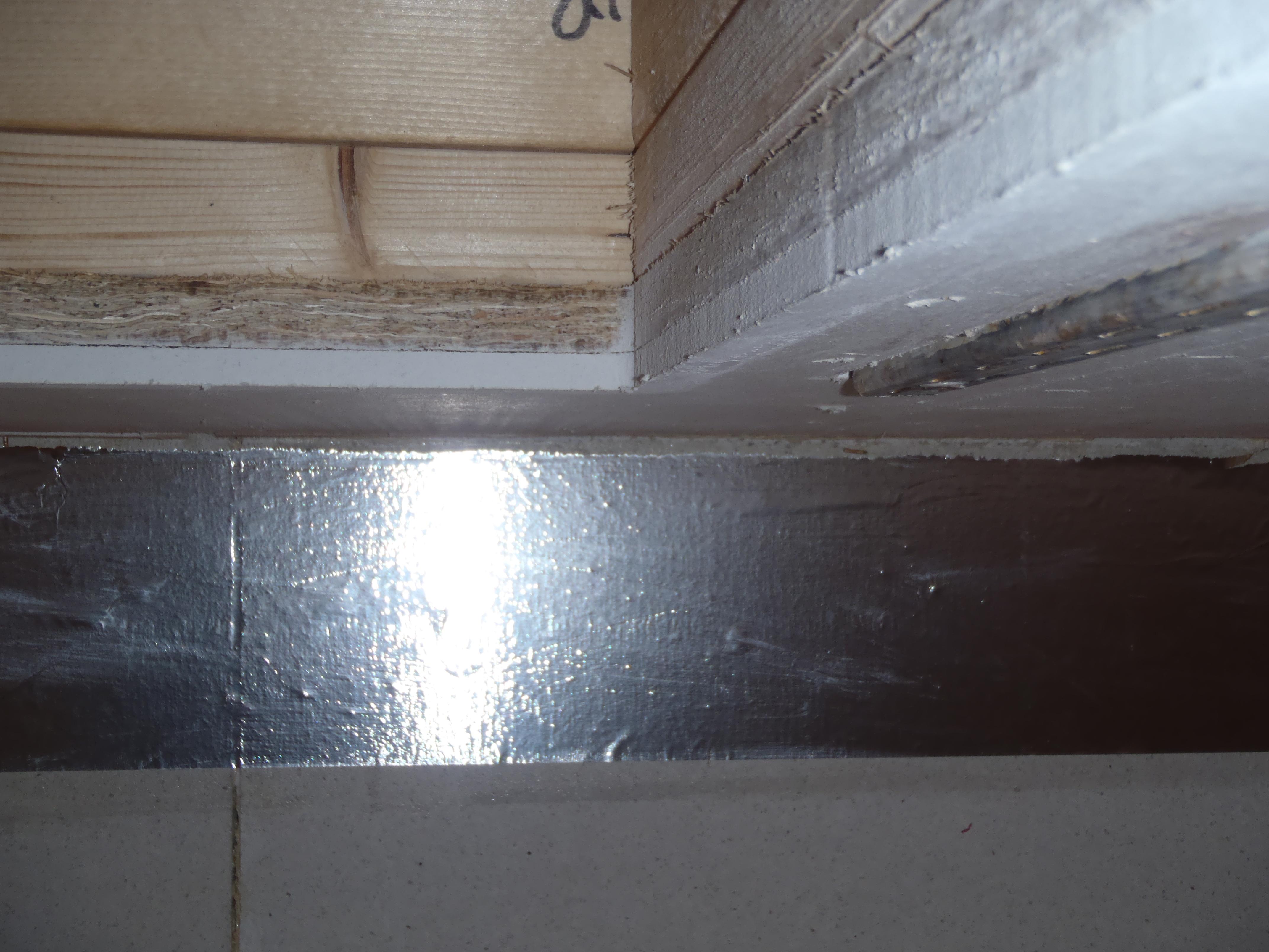
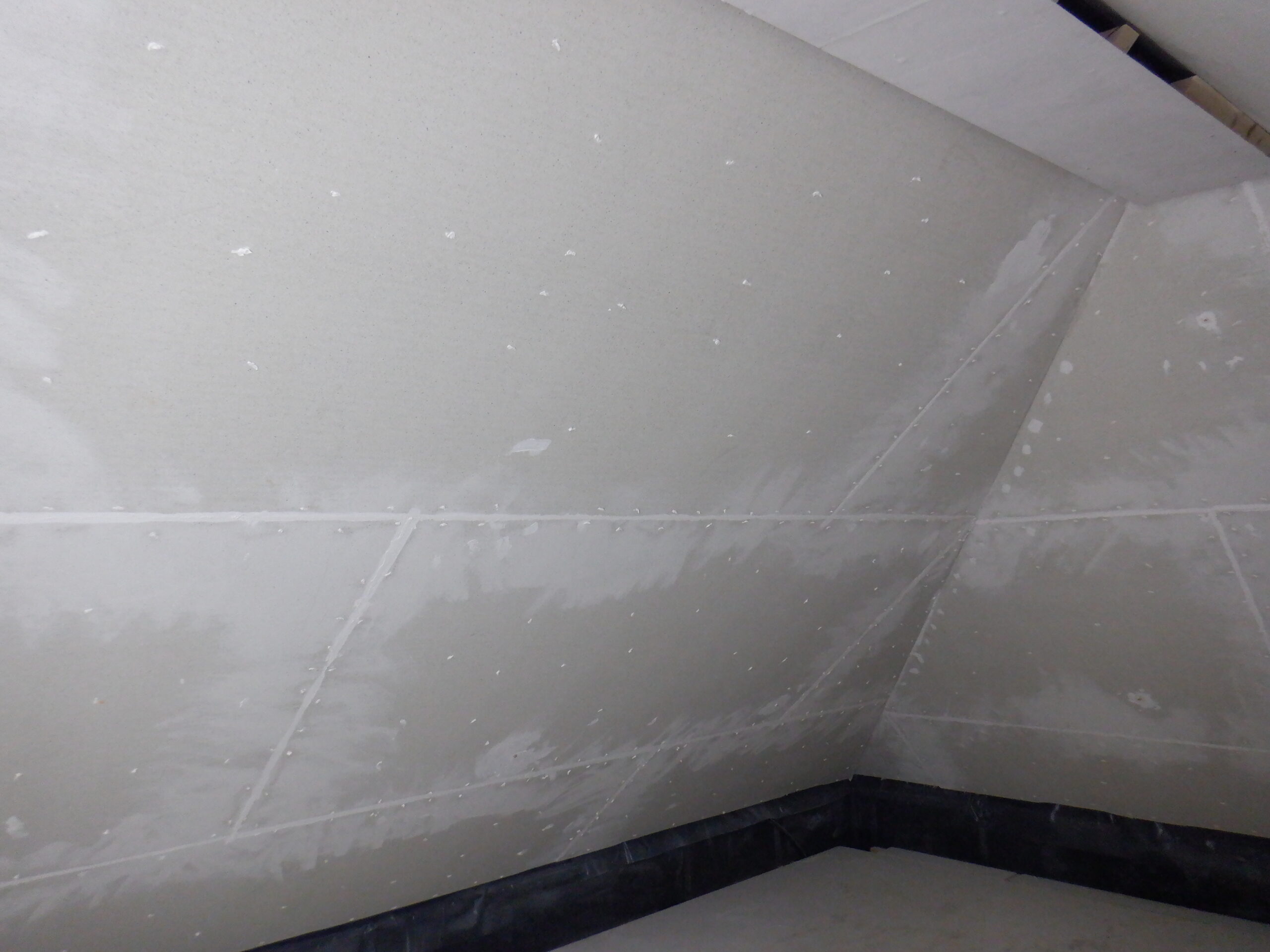
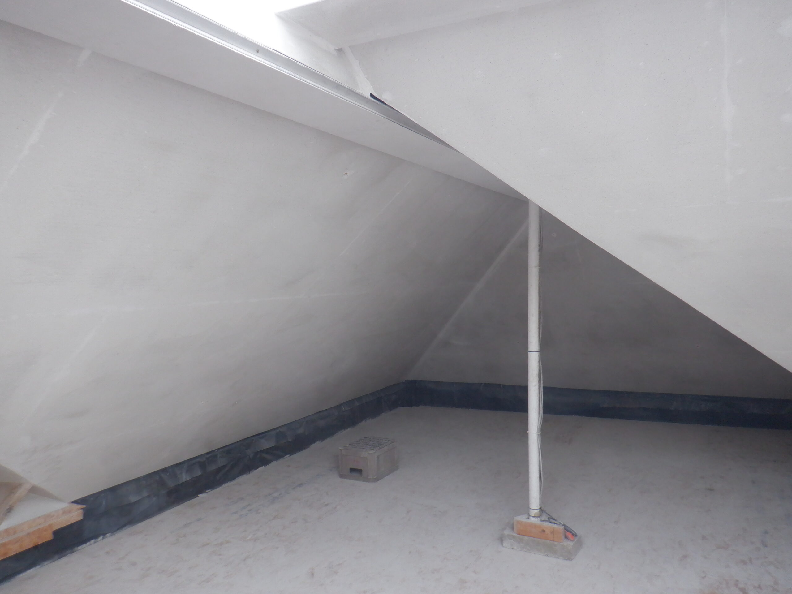
The intersection angle between two roof surfaces were trimmed and also smoothed with heavy use of the sander and manually using a surform shaving tool. We did the “M” and “N” long sloping junction, as well as the Dorma section over the Conservatory, showing off the exposed rafters. These were also filled in with filler especially around the exposed rafters so it comes out all in a straight line in both surfaces as they meet together.
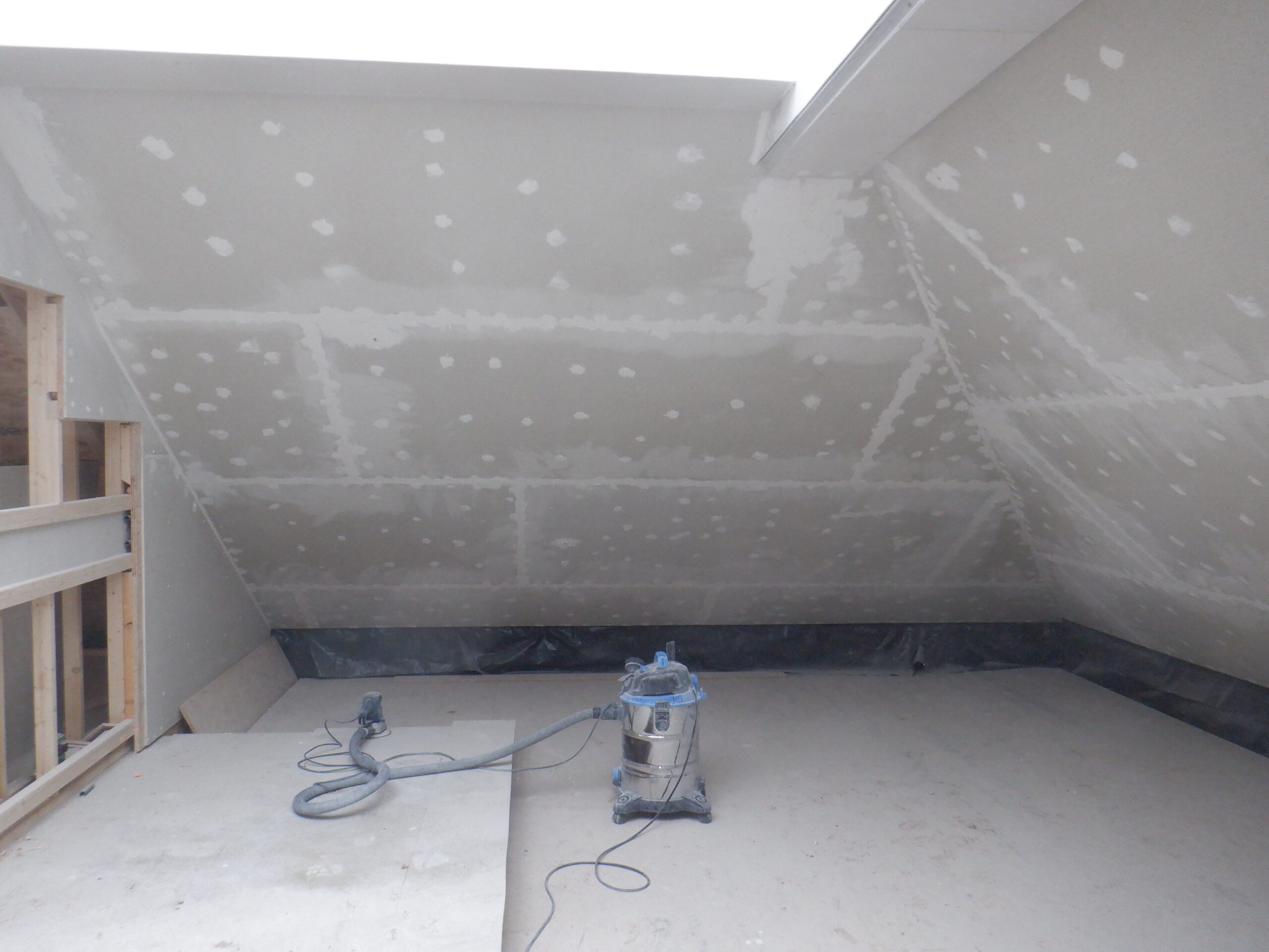
Then came the messy job of rubbing down all the filler! Fortunately, our orbital sander had a vacuum port, to suck up 99% of the dust. We had another lovely tool to help us with this task, a 9inch rotating disc sanding machine attached to a long handle grip, with the vacuum tube running up the handle. This made quick work on sanding down all the surfaces and only needed hand sanding around the edges and corners.
Oh yes, we filled in the three corners between the sloping rooves, by using a piece of 110mm diameter drain pipe as a shaped spatula, to create a smooth curved surface to smoothly sweep around from one surface to the next.
Initial sanding A
Initial sanding O&P
The Gallery section also had all the staple holes and joints filled in, including rounding the corner on the three edges around the doorway, and then all smoothed down too.
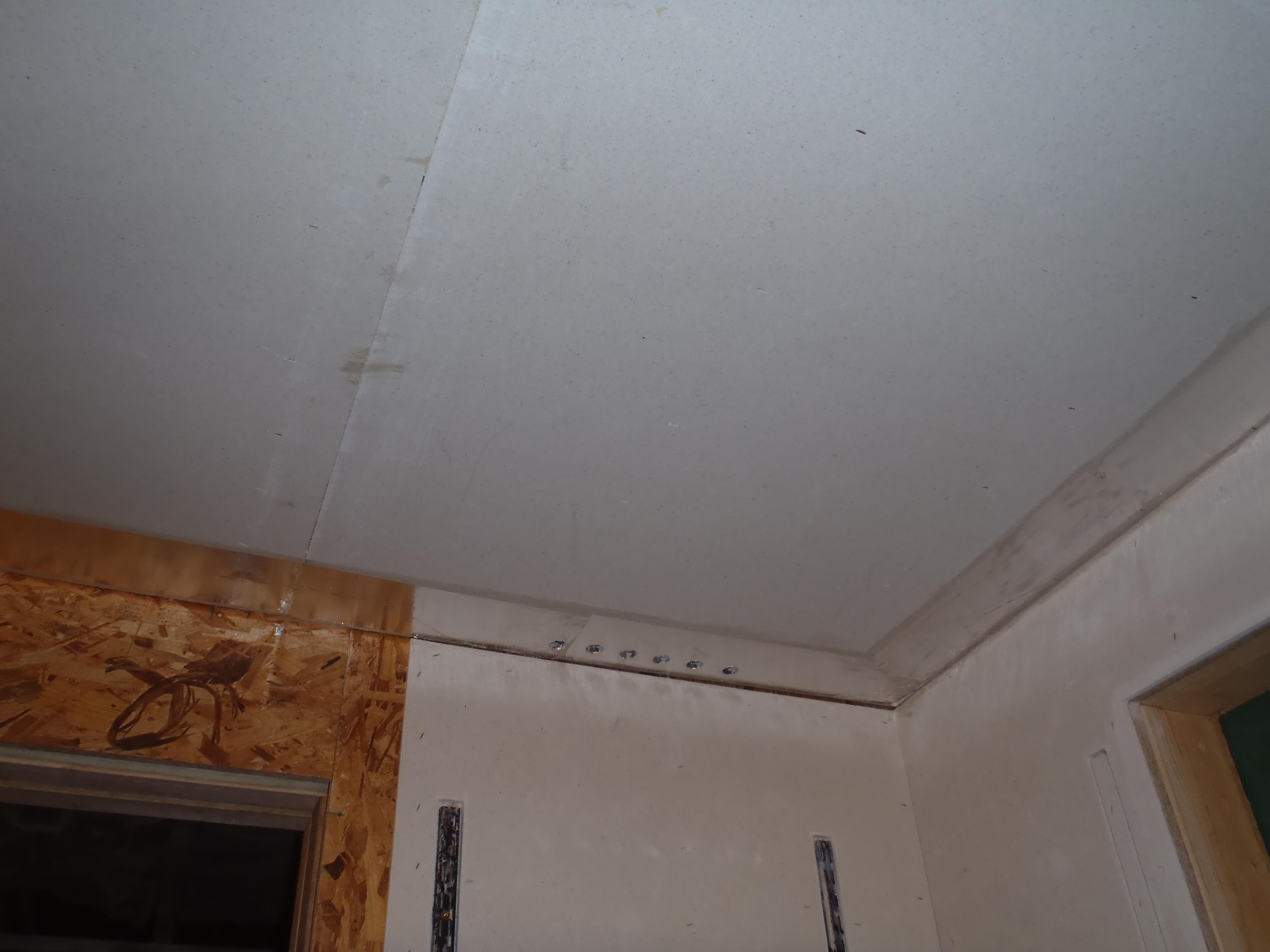
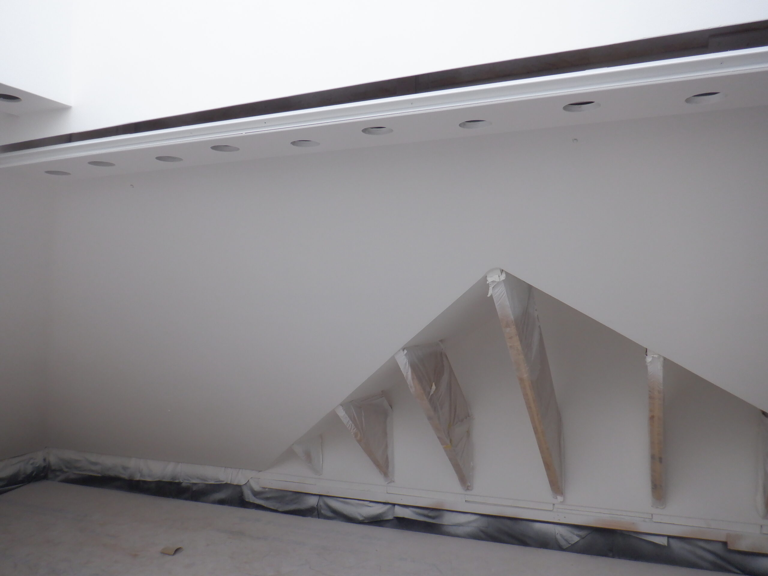
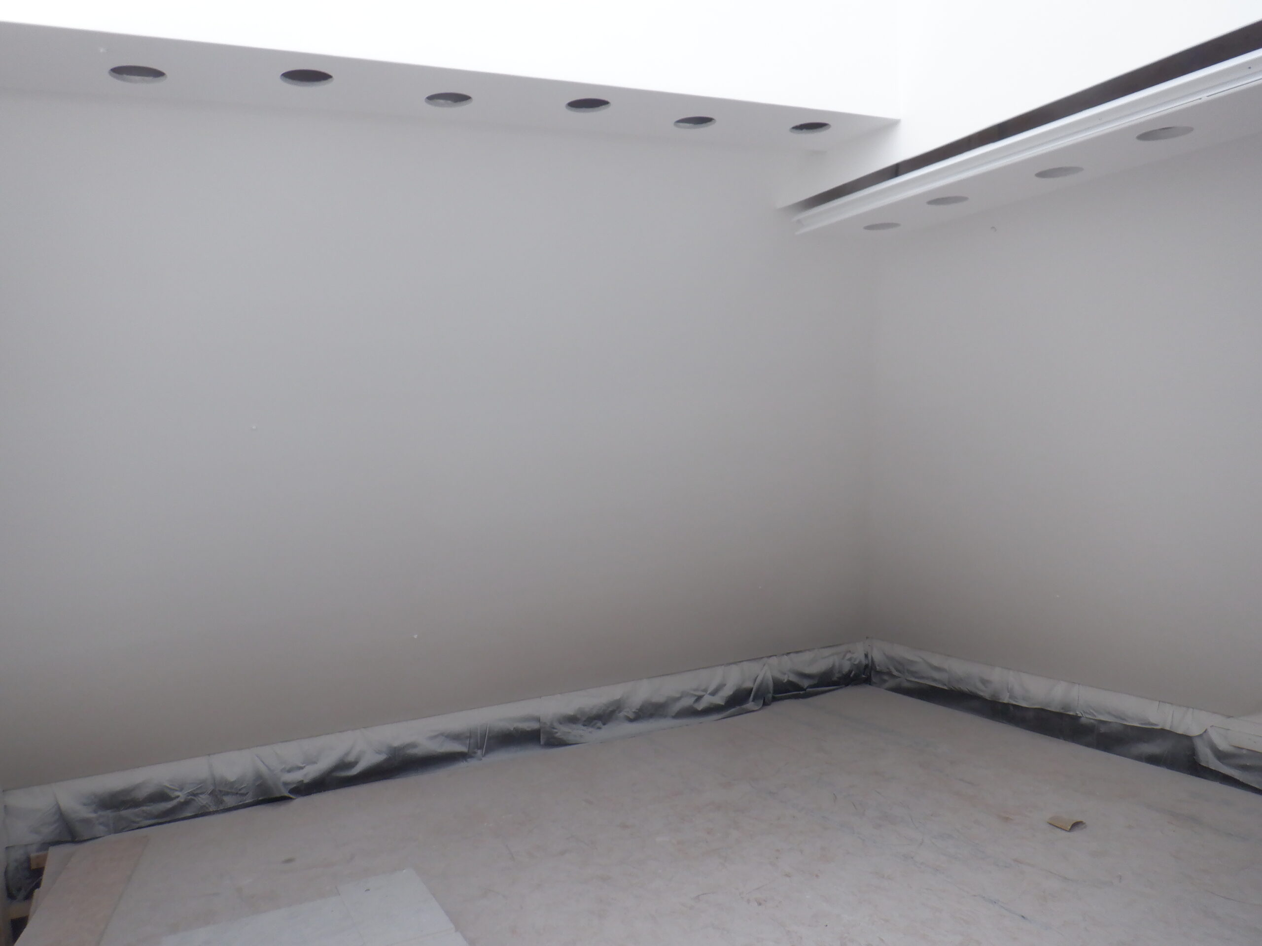
The next task was to drill large holes for our lighting units we are going to have in the two wings of our Skylight, the flat strips that are coming perpendicular out from the Gallery wall and joins to the Skylight. We bought a sharp tungsten carbide teeth circular cutter measuring 95mm in diameter and proceeded to drill a set of eight holes staggered across the surface on each wing.
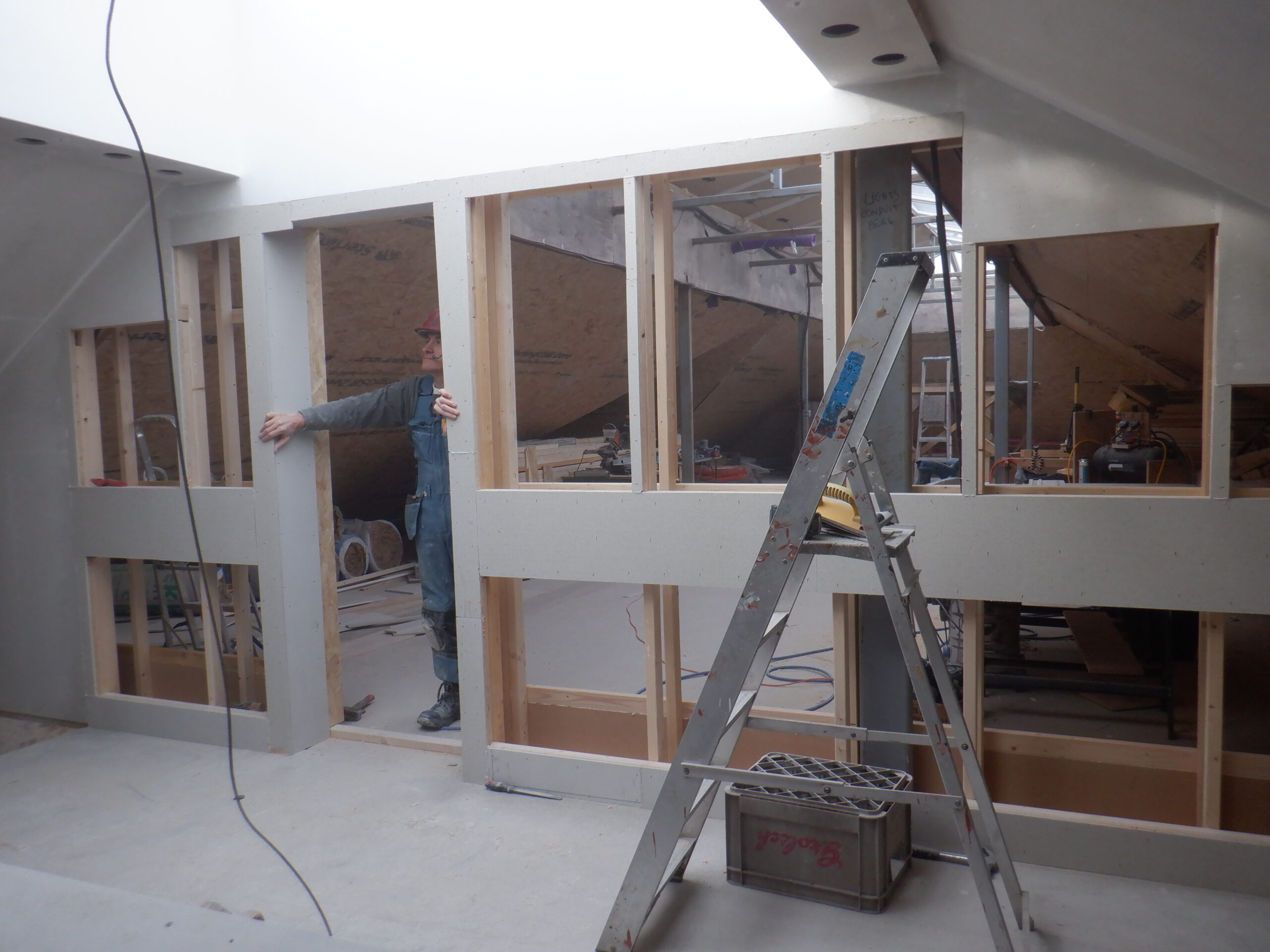
Gallery Wall Built
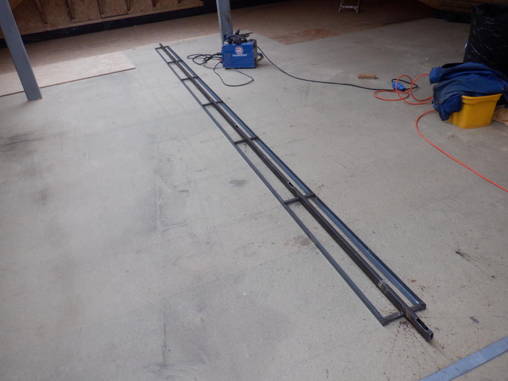
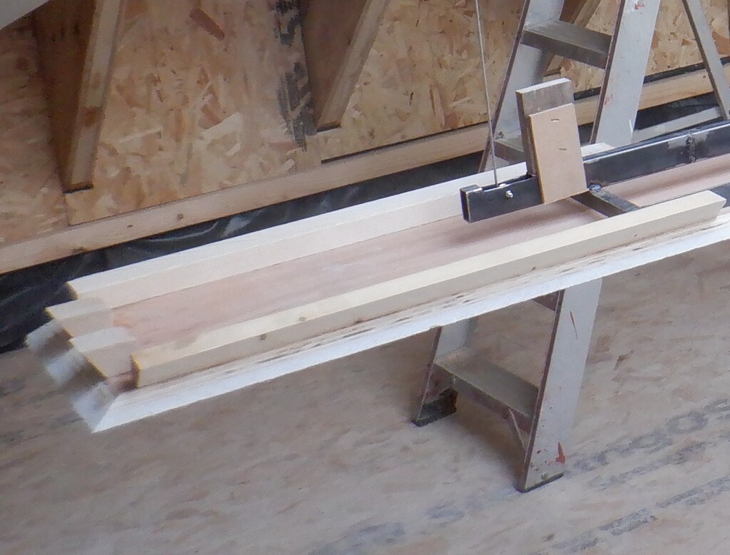
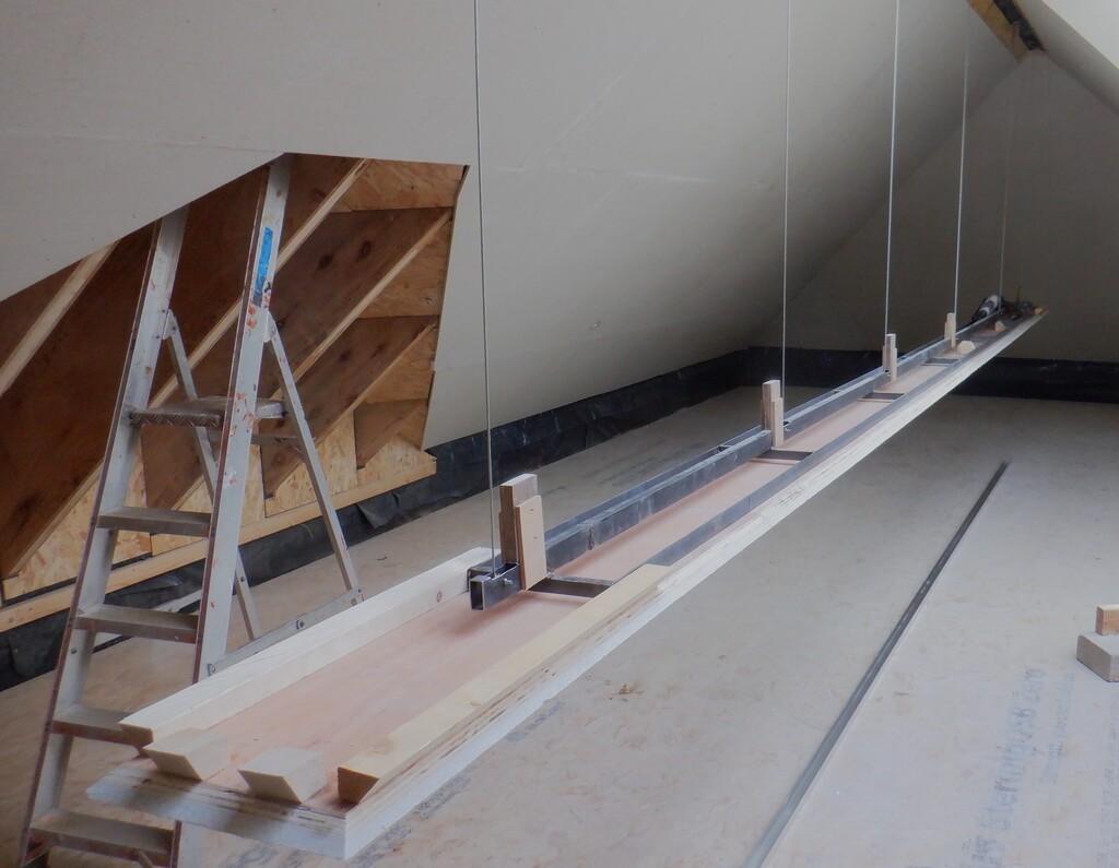
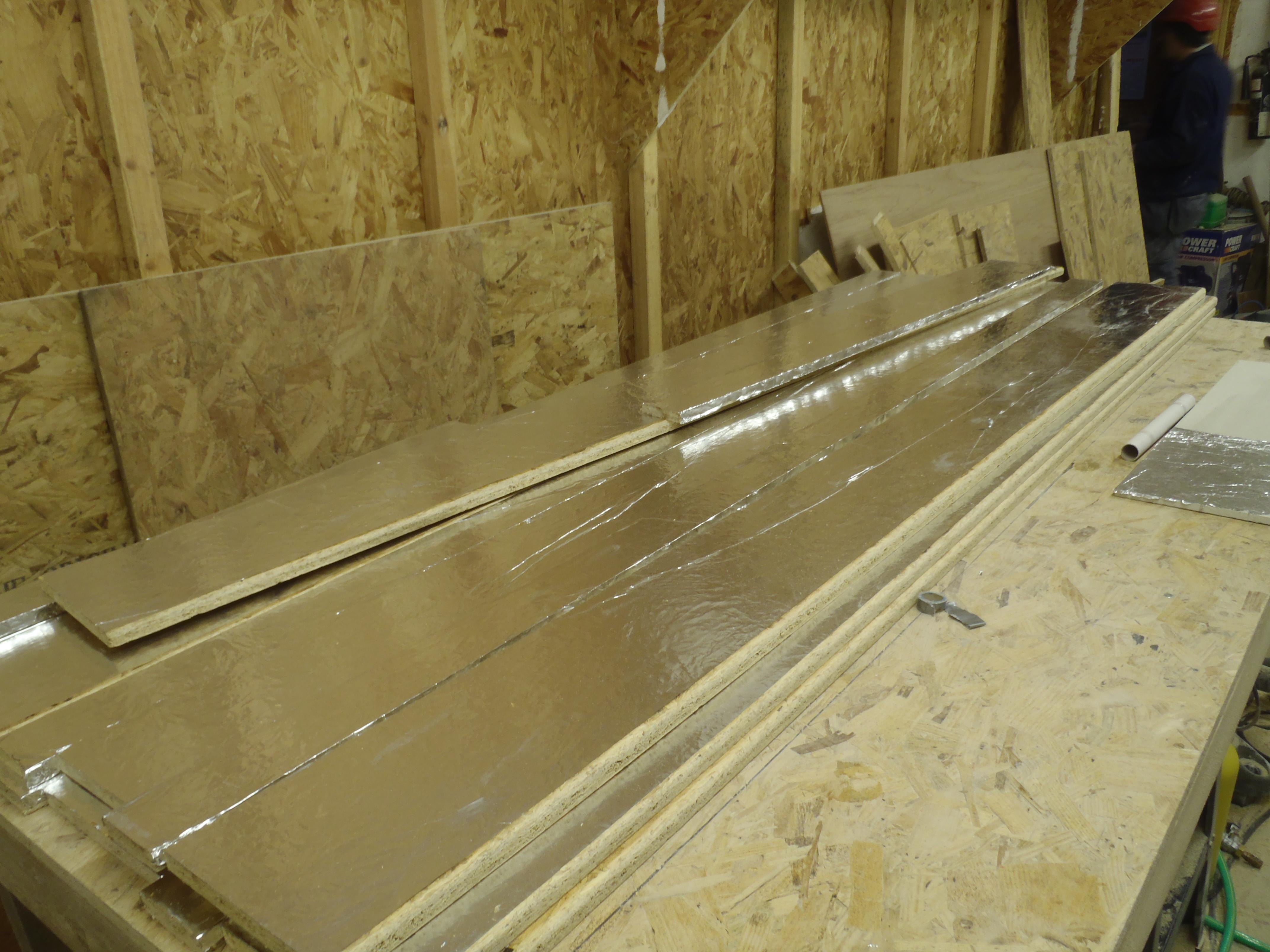
We also lowered our mobile Lighting Gantry unit and turned it upside down on four trestle tables so we could finish with that as well. We first installed the aluminium U-channel bars, which will contain strips of LEDs to shine down the slopes of the ceiling, all the way around the edge of the lighting module. Then we surform the fermacell edges that overlapped the U-channels so that both came together with a smooth graceful line. While we remembered, we stuck down a line of masking tape inside the aluminium channels, at the base so that we had still a bare strip of metal after we had painted them white, for the LEDs to have a good thermal conductivity to aid keeping them cool and long lasting. Most LEDs products these days are over driven and have very poor thermal cooling, and unfortunately, these lamps have short lives. We do not wish to suffer this fate so our LEDs will be under driven, well cooled and hopefully long lasting- fingers crossed!
Anyway, back to the gantry module, we then sanded the flat surface to make sure the joins are smooth and any screw points that pushed a little hump out, is all cleared away and left flat and smooth. Then, we drilled a further twenty-four holes, equally spaced out all the way along the module, only having to adjust very slightly their position twice to avoid internal metal framework. We now have plenty of downlighters to help illuminate our Great Room!
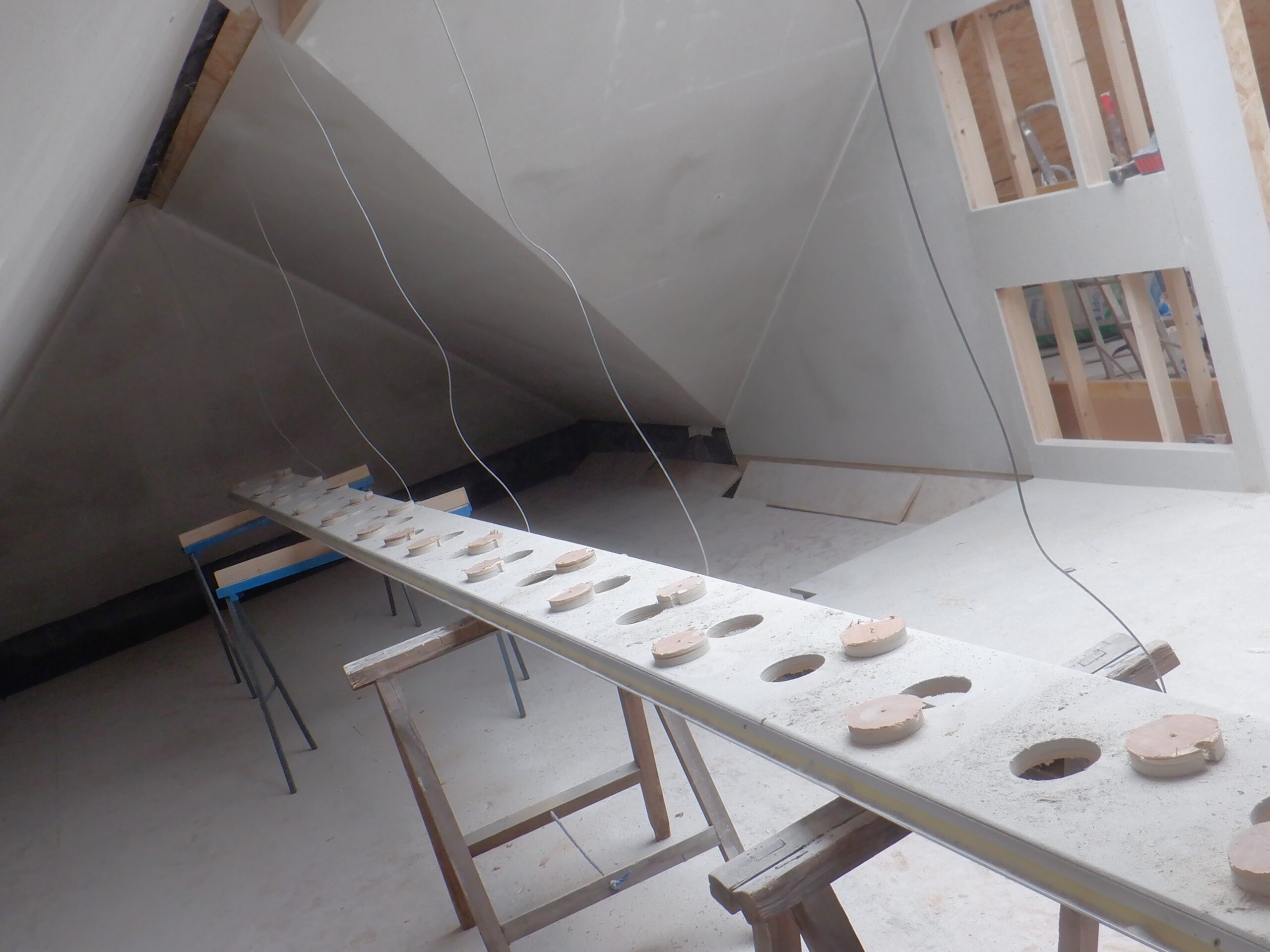
Gantry Spot light holes drilled
The other thing we did to the lighting module, was to take one length of the aluminium U-channel and cut a very shallow groove inside the metal surface, near the front so we can slide in a short length of plastic diffuser in the section that will look over the Gallery under the Skylight. We didn’t want to have the LEDs fully visible, poking their bright pin prick light sources at you, and also to avoid being able to see the electronic control circuits as well.So we were getting closer to the actual painting at last. We double checked everywhere, put in any filler in missing holes and scrapes, installed a little conduit under the cupboards on the Gallery for future lighting options and then gave the whole area a good and thorough vacuum and sweep. Also washing with plain water all the painting surfaces with a floor mop to remove any dust, sanding a couple of missed “bumps” along the way!
We then covered up the naked exposed rafters with masking thin plastic sheets, to protect the wooden surfaces so they can have the “pretty” veneer stick nicely to them .Finally, we can actually proceed to the painting at last! We got out our paint sprayer and got our 10 litre of white emulsion paint. It was quite thick and the sprayer said that it should be diluted with water, to make it thinner. It recommended a minimum of 10% of water and that the paint dribbles off smoothly and doesn’t form “bumps” or “tracks” in the paint before settling down. We ended up diluting it to about 12.5% before it looked ok. We had two spray nozzles and the wider fan nozzle, doing 50degrees wide fans, seem to be making a slightly bumpy surface on a sheet of insulation board. We switched over to our second nozzle, which produces a finer and narrower 30degrees fan, seem to be better.
So we proceeded to spray the ceilings, starting on the “A” section and working around clockwise. We managed to cover almost all the ceiling surfaces before we ran out of paint. We were surprised that we couldn’t get the 10litres to last long enough to cover all the ceiling and walls. The instructions on the paint pot claims that it should cover about 130 square metres and we estimated that our Great Room ceiling and Gallery is about 70 square metres. It looks like that we had put it on too thickly. Then, we spotted that the paint pot also said that they recommend diluting their paint 25% if one was using a sprayer. Oh Dear!!
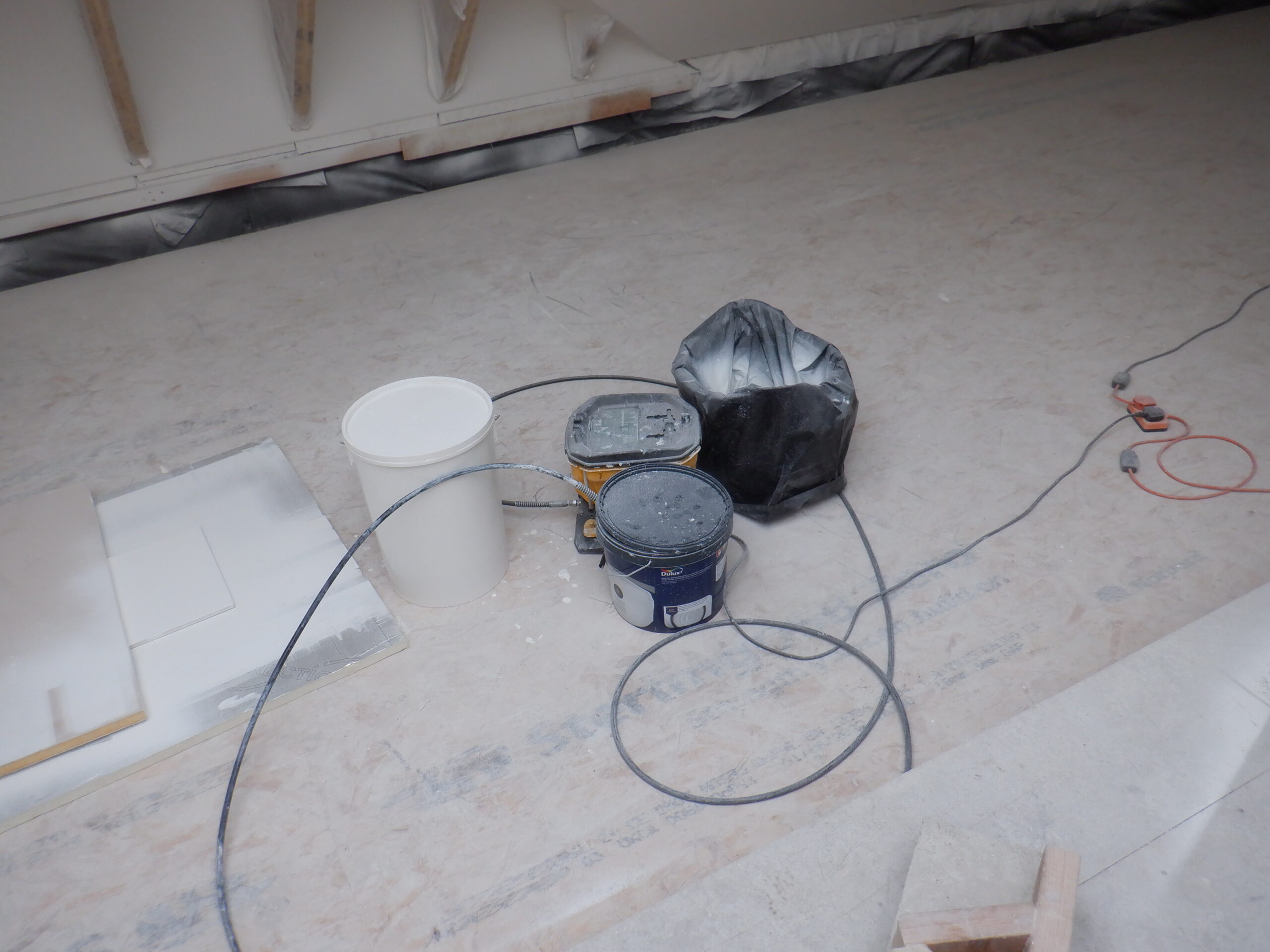
Paint spraying equipment
In the full daylight on the following day, we also noticed that we had missed sections. We were painting in the late afternoon and we hadn’t had enough lighting. We are learning!!
Another side-effect we have discovered, is that the fermacell plasterboards, which are made up of newspaper pulp mixed in with the gypsum, goes “hairy” when we do heavy sanding on the surface, like when we had to smooth out a joint. The paint has soaked into these hairy bits and produces a textured finish. But fortunately, we also discovered that by just simply sanding the surface with 240grit paper, it knocks off the hairy bits completely in one single swipe of the sanding paper. So, we went around the whole room with our large circular sanding machine, loaded with 240grit paper and got everything nice and smooth. This is good news and rather pleasing that it came out very nicely indeed.
The next discovery, was that we had missed several staple holes, staples that were not fully hammered below the surface and various gouges that revealed themselves by the high contrast colour of the white paint. We went around with more filler and touched up these spots.
Our new tubs of white emulsion, this time buying Dulux branded paint and discovered that their domestic grade paint is much thinner than the previous one we were using. We only needed to add 10% water to get it running and dripping quickly, as recommended by the sprayer people. We then used the first nozzle, the 50degrees fan and proceeded to finish those area we undone and we had to stop early to allow all that lot to dry and harden.
On the following day, we went around sanding smooth all the blobs of filler we had put on, gave the Gallery wall a gentle rub to nock off the hairs and even now, we keep coming across a missing staple hole once or twice. There was a case where we had accidentally put on a strip of the fermacell back to front and the manufactured grid pattern was visible. This was the narrow strip up inside the doorway on the Gallery, so we diluted our filler mixture and applied a thin layer all over its surface using a wide bladed scraper. And just to finish off our morning’s work, we proceeded to spray the second coat of “Pure Brilliant” white paint everywhere, using well over another 15 litres of paint. It seem that we cannot help putting on more paint than what the tin says. We just shrug our shoulders and it is not a great expense, considering the cost of the underlying material we had already invested in.
After lunch, we rubbed down that doorway surface, which came out extra smooth and gave that a coat of paint. While we were waiting for the second coat to dry, we remembered that we needed to cut two pieces of the aluminium U-channel, for the two Skylight Wings, to provide more lighting output to shine down the slopes of the ceiling. We took the metal channels and cut the grooves to hold the plastic diffuser strip and drilled a cable access port plus screw holes to fix the bars up and stuck down a strip of 19mm wide masking tape, like before, to maximise thermal transfer of heat being generated by the LED strips. Finally, we gave them a spray of paint as well.
On the morning, the surfaces were again very gently sanded, to get rid of more hairy patches and after lunch, use our finishing coat of white paint, this time using a brighter Absolute White colour, which claims that it will reflect 90% of the light back into the room. The colour of this Absolute White is definitely “whiter” than the previous paint which is called Pure Brilliant White and it says that it has a 80% reflectivity of light. This paint has a very very very slight yellow tinge to it, especially comparing against the new Absolute paint we had put on.
Upon the following day, the surfaces are looking much much better and we are definitely winning against any more hairy patches showing up. In the sunshine, we could see several patches of a slight difference in “Whiteness” so they got an extra squirt from the spray machine. And, after lunch, those patches have disappeared and it is looking very good indeed. We have decided that the job is finally done!
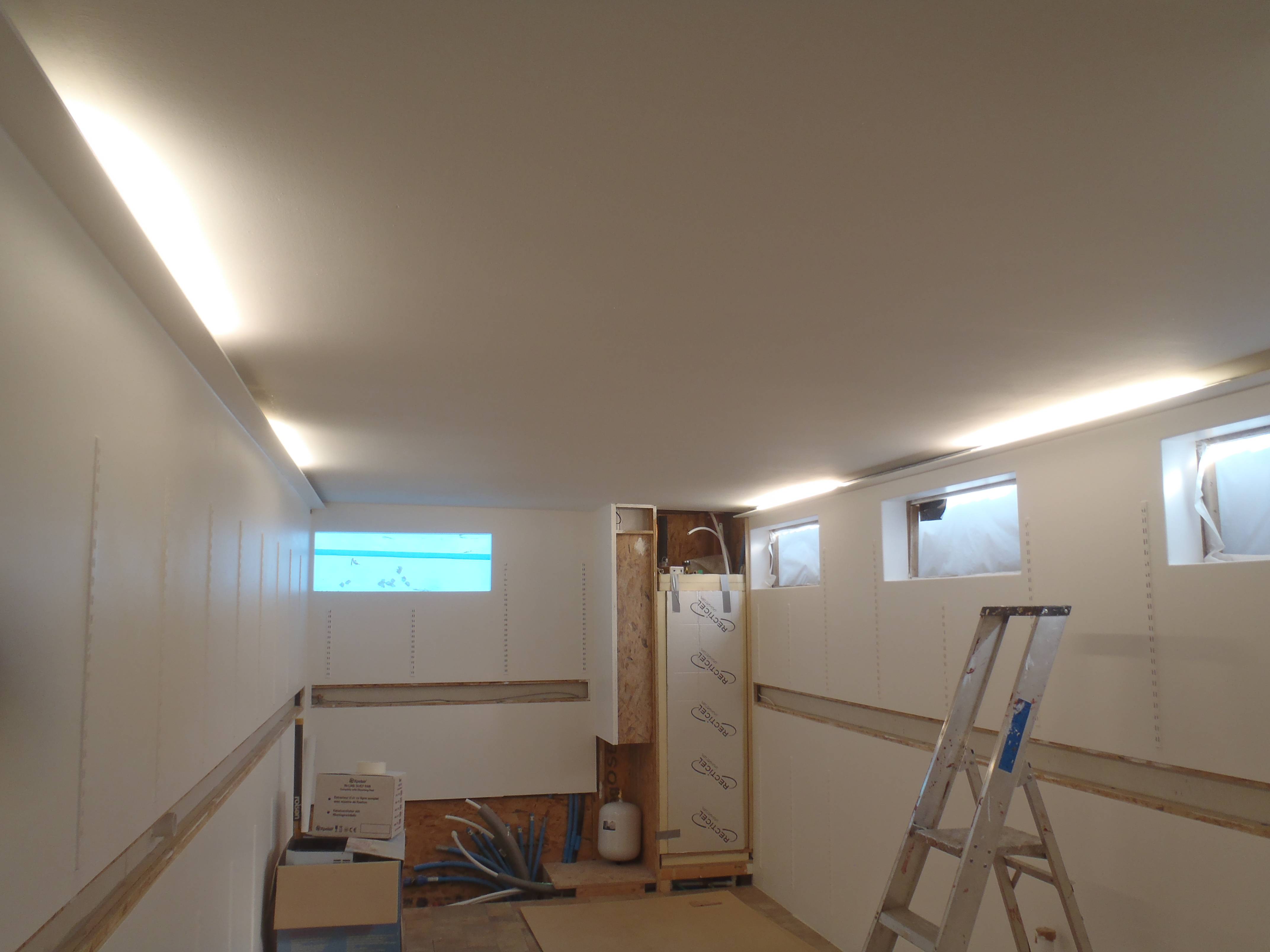
All painted (1)
All painted (2)
All painted (3)
There had been a great deal of learning involved during this particular task of building, preparing and finishing the final “plaster” layer for the ceiling and walls. We now know what to expect, what to do, when we repeat this kind of work again on other parts of the house, and it should be easier and quicker.
The next job to do, before we dismantle the temporary flooring, is to cut and shape our wood effect laminate sheets and cover the exposed rafters at the Dormer section over the Conservatory.