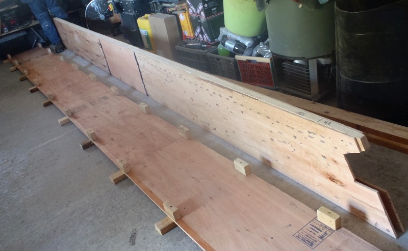
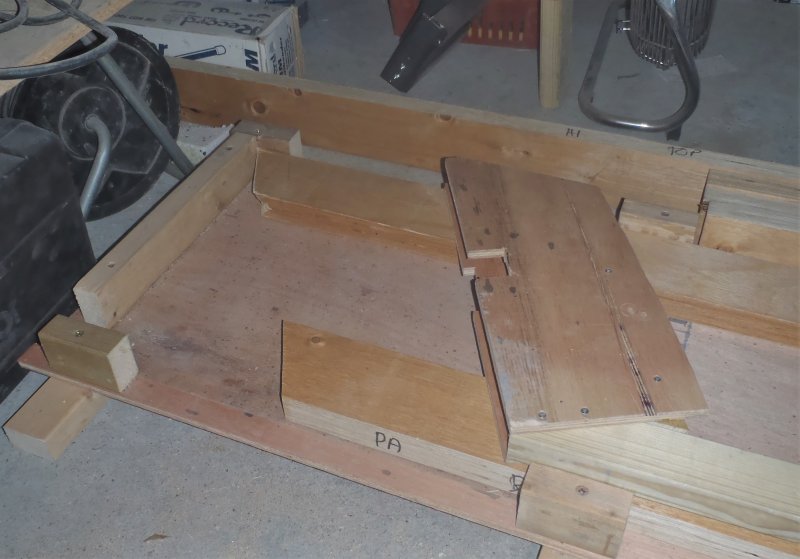
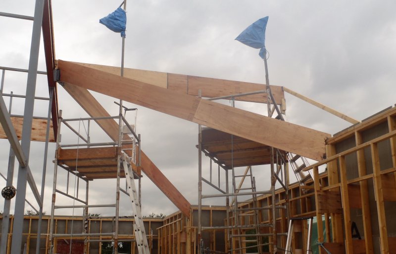
This morning, under a very nice sunny blue sky, we took out our completed PA Hip Rafter from the workshop to the building site, and after positioning the towers into place and trying 3 times to lift it up, finally made it to get it into place just before lunch!
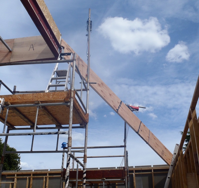
Rafter-PA-lifted-into-place
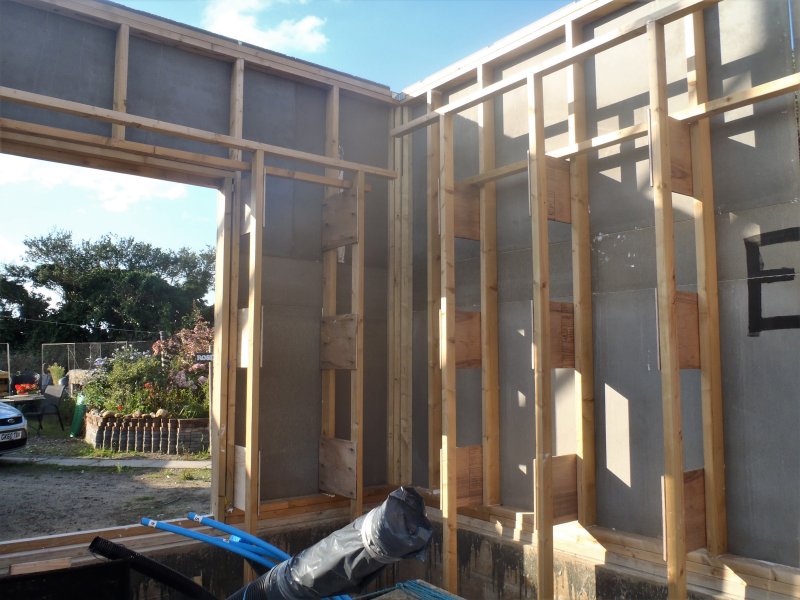
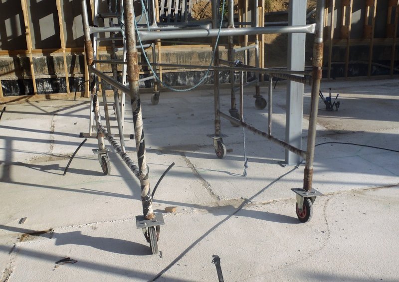
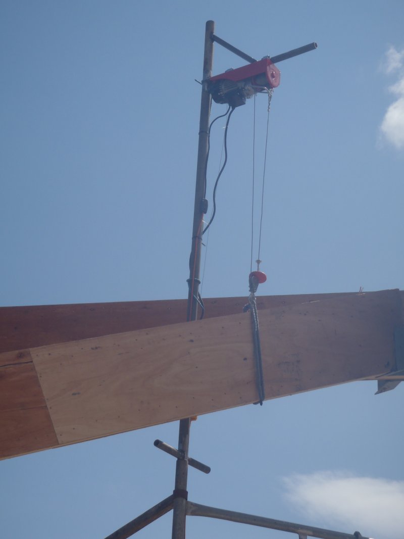
The trouble was that this rafter has a long sticking out bit that forms the Eves of the roof and goes out to the facia board and the guttering. This meant that we couldn’t lift the beam high enough one way and ran out of lifting wire on the winch before we could get it up. We finally shifted around one of the towers so it gave us more freedom of movement and also hit on the idea of lifting the other end (the end with the sticking out bit) first into the air so it overhung the wall entirely and this allowed the other end to come up and miss the obstacles on its way up! Phew! Oh yes, it fitted just fine!!
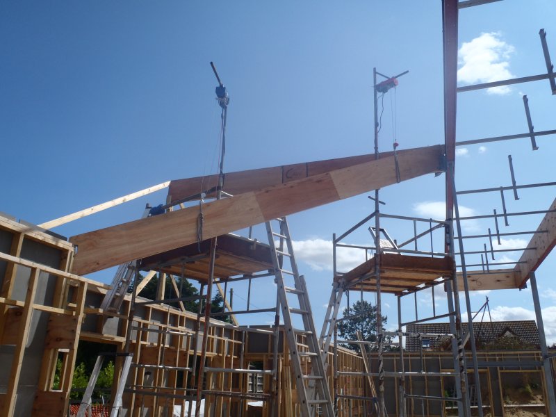
After lunch, we smeared lots of glue all over the joints at both ends, up and down the leg and on around the top-plate of the wall. We wiggled and banged the rafter into the corner and inside the leg, and also slid into the metal bracket and against the kerb at the top too. All then was fixed down with nails and screws to hold it while the glue sets. Hooray At Last!!
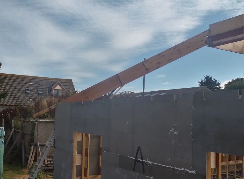
Rafter-PA-Installed
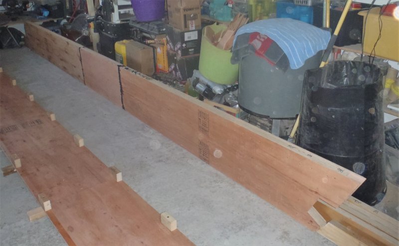
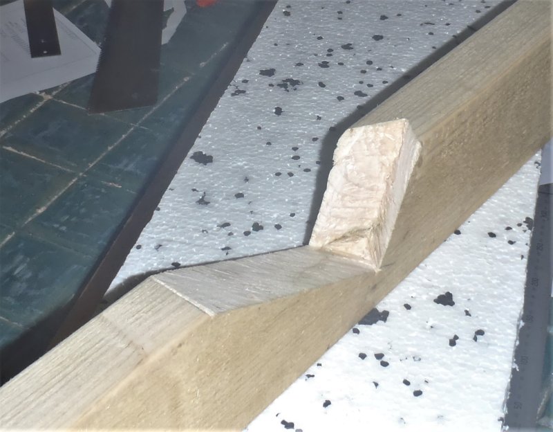
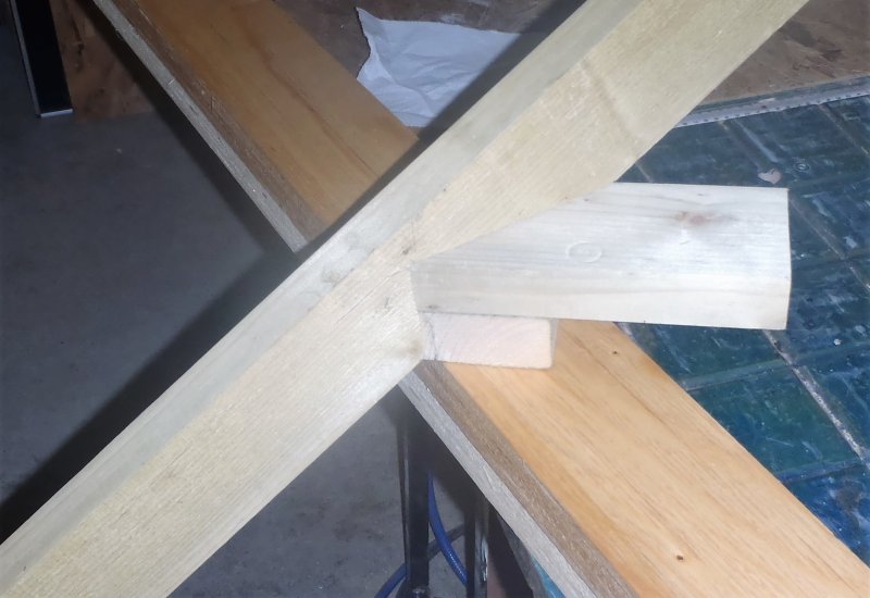
We carried on by moving the towers across to the next corner, the EH corner in the Utility Room and got our templates to measure the distance of the top flange which turns out to be 5570mm long. Inside the workshop, we took the correct LVL timber, sliced a flat bottom on one end and an angled cut upwards, and then measuring from that point, marked the timber at the other end at the 5570mm and drew the inverse arrow head with the tilt backwards. This end goes up and connects to the kerb of the Skylight. We carefully sawed out this inwards facing groove and took it outside to test it. Yes it fitted very nicely!
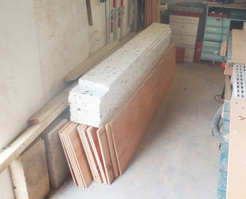
Finally, we removed the excess plywood sections on all the strips, both for the EH rafter but also for the other corner, HI too. We transferred the pattern over from the HI webbing to the EH but in a mirror orientation so all our webbing is now ready for sanding and assembling into rafters tomorrow. We hopefully can get both of them glued and squeezed together and have them dry and ready to go either Friday or Saturday. Fingers Crossed!! Grin!