Category: Skylights

The 16metres by 2.5metres window to the Sky!

  • Dealing With Desiccant Dribbling All Over Plywood Liners – Part 1

    Now, we have reached a major decision to make. We have been thinking about the problem where our attempt to control the condensation up above the double glazing had failed and the calcium chloride desiccant material has dribbled all over our plywood boards that we have lining up inside our Skylight. We tried to dry this constantly moist surfaces, using both a hot air blower and even a gas blow torch, to cook the crystals, trying to break them down etc. But, alas, it didn’t work. The plywood would go wet again after a day or so, and it is not because new water was dribbling in as we had glorious sunshine and dry weather for 10 days. It is probably the original desiccant is reabsorbing the moisture from surrounding surfaces, or straight from the air.
    So, what do we do?

    Do we try to cover this mess up? Put a line of plastic over it to stop the moisture staining our finished plasterboards? Or, paint a thick layer of varnish on the back of the plasterboard?

    But, this is not good at all. This means that the plywood will stay damp for years and years because the calcium chloride desiccant holds on to the water forever. Also, the calcium chloride liquid is slightly corrosive and we got our main heavy duty steel RSJ beams up there supporting the whole roof and Skylight.

    No, we are going to play safe.

    This means ripping off all the “infected” plywood and replacing it with fresh new material. We decided that we can use 11mm OSB boards instead of plywood, as it is not a structural element of the Skylight. We ordered 10 sheets and they will arrive soon.

    In the meantime, we went along the Skylight, on our trusty platform, to pull off each piece. They were both screwed and glued on!! It was hard work yanking off each sheet! The glue was so strong that we were actually ripping a layer of ply off the back of the boards! We tidied up all these broken strips of ply, removed broken screws and generally got it cleaned up.

    Lining stripped

    Lining stripped

    A contaminated board

    A contaminated board


    Now that we have removed the plywood covers, we can see in some locations where the desiccant liquid has managed to get behind the plywood and soak the timber and the top of the steel RSJ itself.

    So, we need to neutralise his liquid and the web says “use soda powder, which is sodium carbonate” or “use baking powder, which is sodium bicarbonate” and this converts the calcium chloride into calcium carbonate, which is limescale. It also produces table salt, Sodium Chloride and in the case of the bicarbonate powder, also produces carbon dioxide gas.
    Nice and simple!
    We had washing soda in our washing supplies so we mixed a good heap of the powder into hot water and dissolved it all. We then filled up a spray bottle and went around squirting on the damp patches and saw an instant reaction where it went white. This being the calcium carbonate. We also got a large sponge and literally soaked the surfaces of the plywood pieces that we had laid out flat on top of our Swimming Lane outside. This also caused the wet patches to go white too. Hopefully, that will solve that problem and once it is dried out, there will be just a mixture of calcium carbonate and sodium chloride salts sitting there and minding its own business.

    We also liberally sprayed all the spots on the floorboard where the desiccant had dripped down from the Skylight. This includes the stair case as well. We deliberately soaked a good amount on the first three steps at the top of the stairs and also wiped the next three steps down too.

    But, in the meantime, we have been attempting to dry out all the condensation that managed to freeze on the outer pane of plexiglass. We had made it worse ourselves because we kept running the air fan all night as well, and unfortunately, we hadn’t realised that the air that we pumped into the Skylight was getting more and more humid, and alas, the moisture froze on the plexiglass, especially during the icy cold weather we had been having.

    So, we needed to get rid of all this moisture first, before we could continue doing the repair work up in our Skylight. to achieve this aim, we rigged up an air drying chamber, using a large rubble sack, put in a water proof plastic tray and put a folded up mesh situated above the tray. The mesh held a large pile of Calcium Chloride crystals, which will grab the moisture out of the air passing through the plastic rubble sack. We made a hole at the other end and connected our air fan, to continue pumping dryer air into our Skylight.

    The results of this operation is that we are slowly winning the battle against all the moisture. The Skylight windows are slowly clearing away and soon we can resume work. We have already had to empty two loads of dissolved crystals and we have just ordered a couple more bags of the Calcium Chloride. We will continue with this operation for another couple of weeks.

    While all this had been going on, We have been working on our Ventilation system downstairs!!

  • Building the Skylight Boxing, creating the Air Ducting and installing more insulation

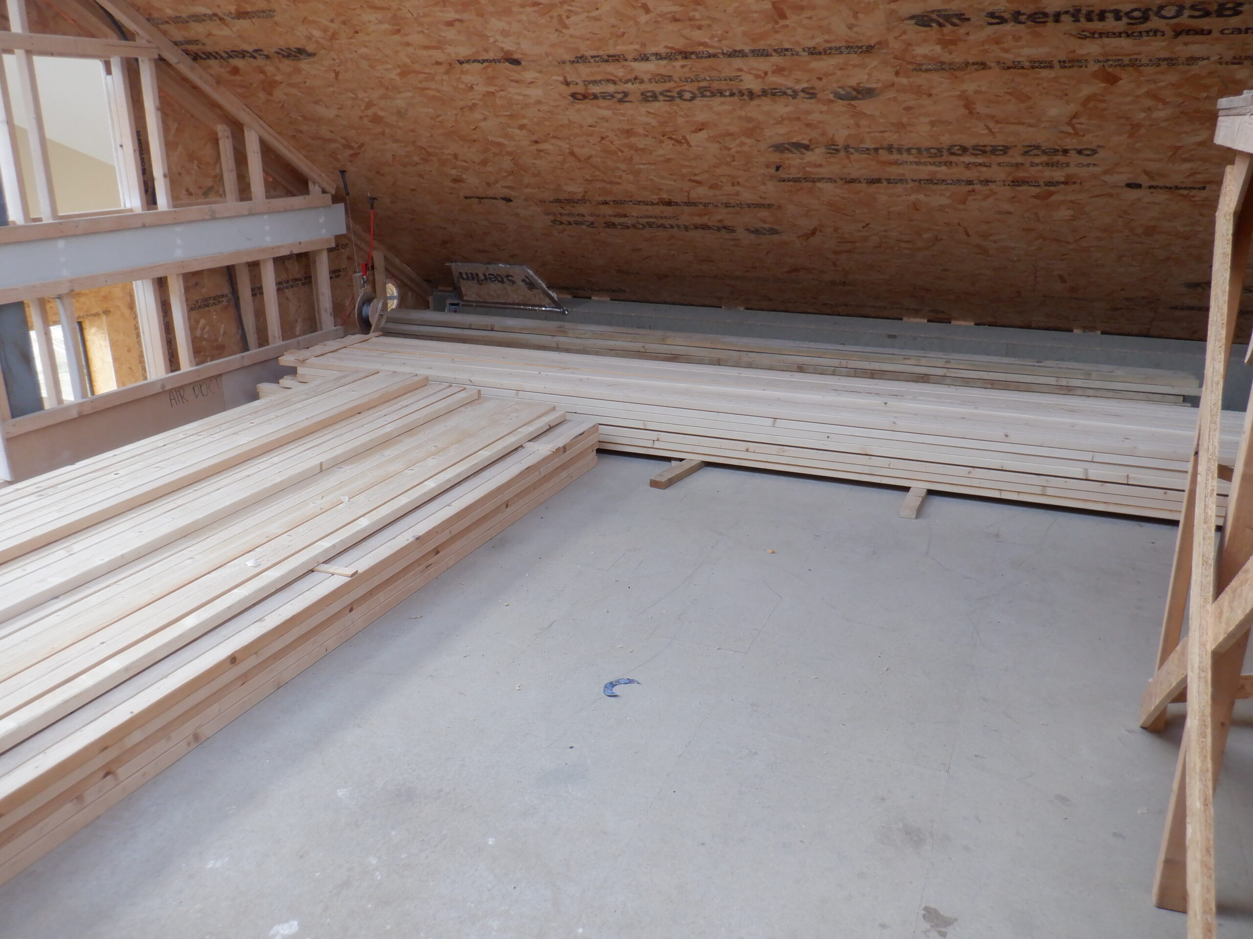
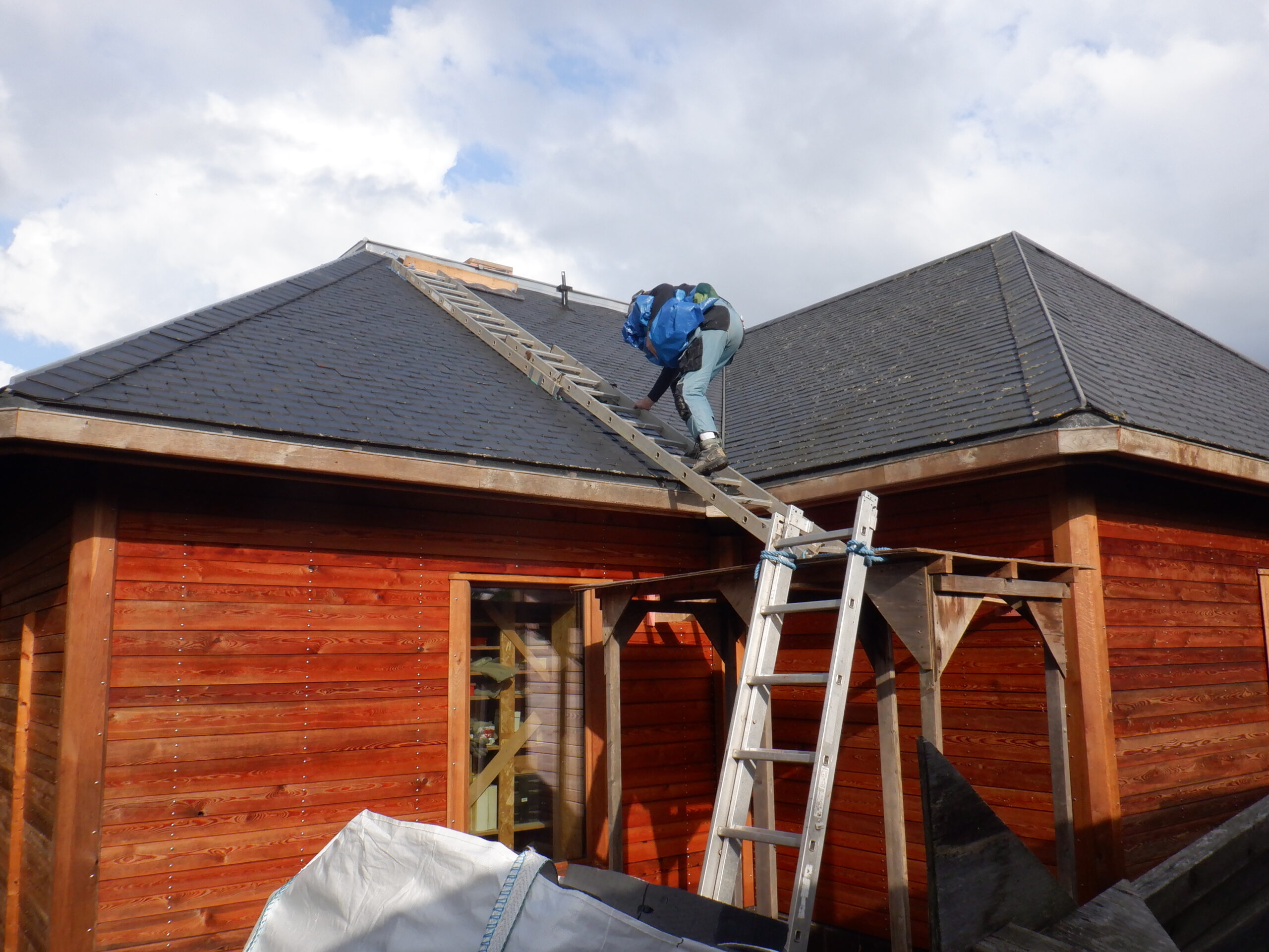
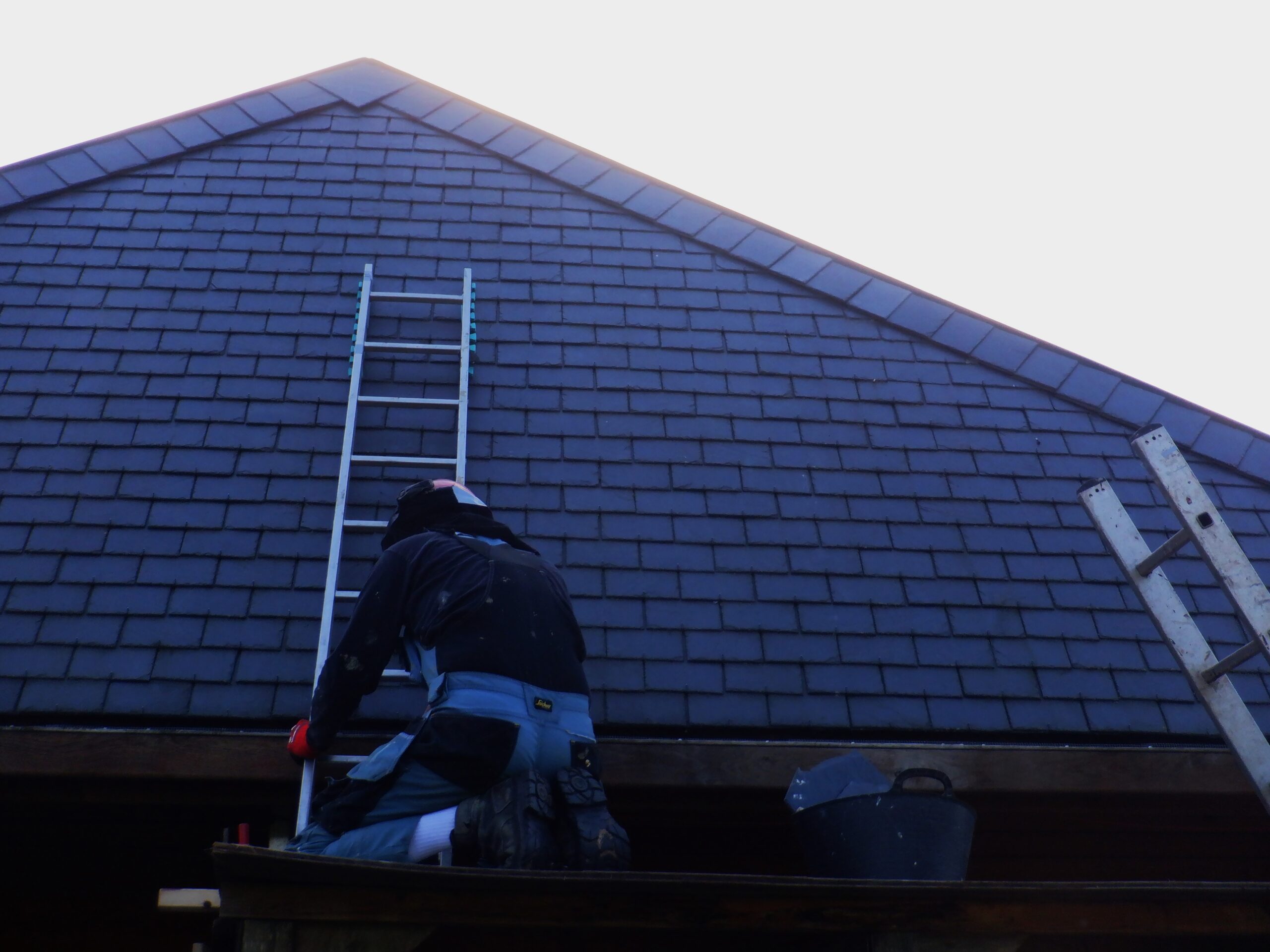
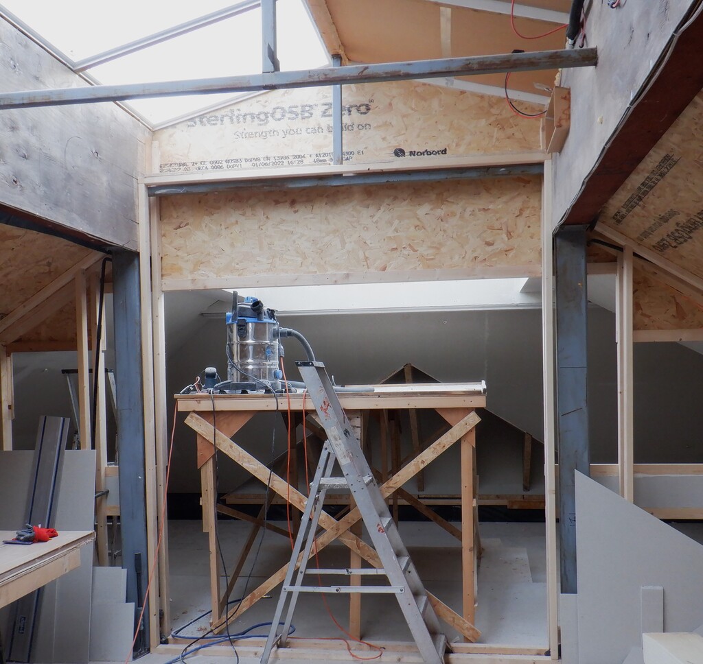
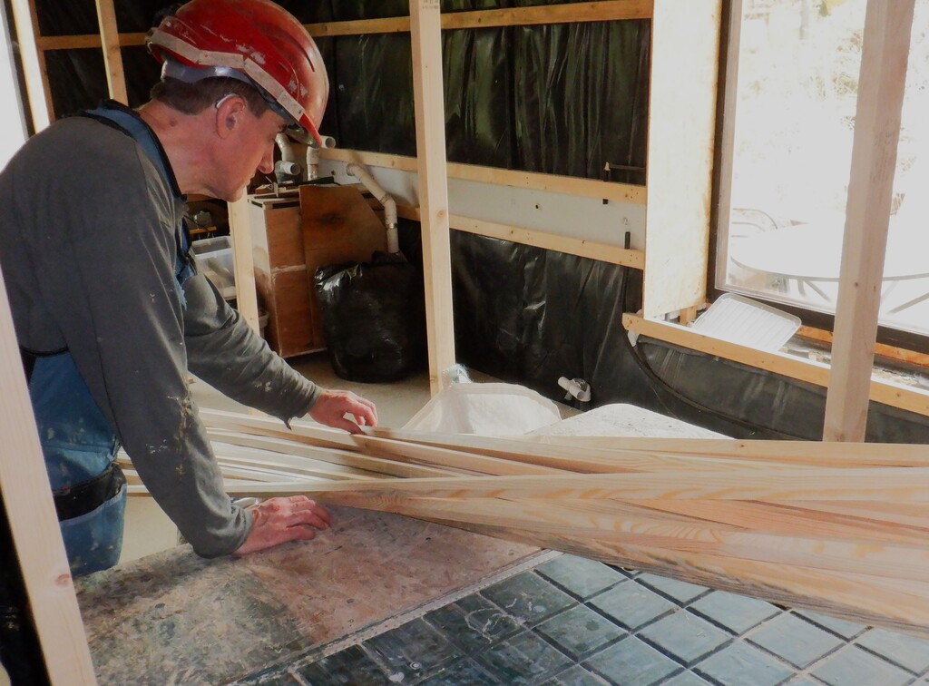
    While the weather and temperature are cool at the moment, we took the opportunity to complete the Skylight while we still had the work platform available. The Skylight is a good 3metres (10feet) up and it would be very awkward to to reach that high up on just stepladders, so, it is just prudent to get on in finishing everything that needs to be done up there, before we have to dismantle our large work platform.One of the first task that had to be done before we got into the Skylight, is to move our stack of 63mm CLS timber planks! It was situated going across the width of the large room just near the Gallery, which meant that it was rather in-the-way of our Skylight work. So, we simply rotated the pile around to the right and stacked up the 200+ planks out of the way, so we can move our platform back and forth lots of times, and get the maximum benefit at a much reduced time and effort. It only took about an hour to move all the timber, which is well worth the effort!!
    Rotating CLS

    Rotating CLS

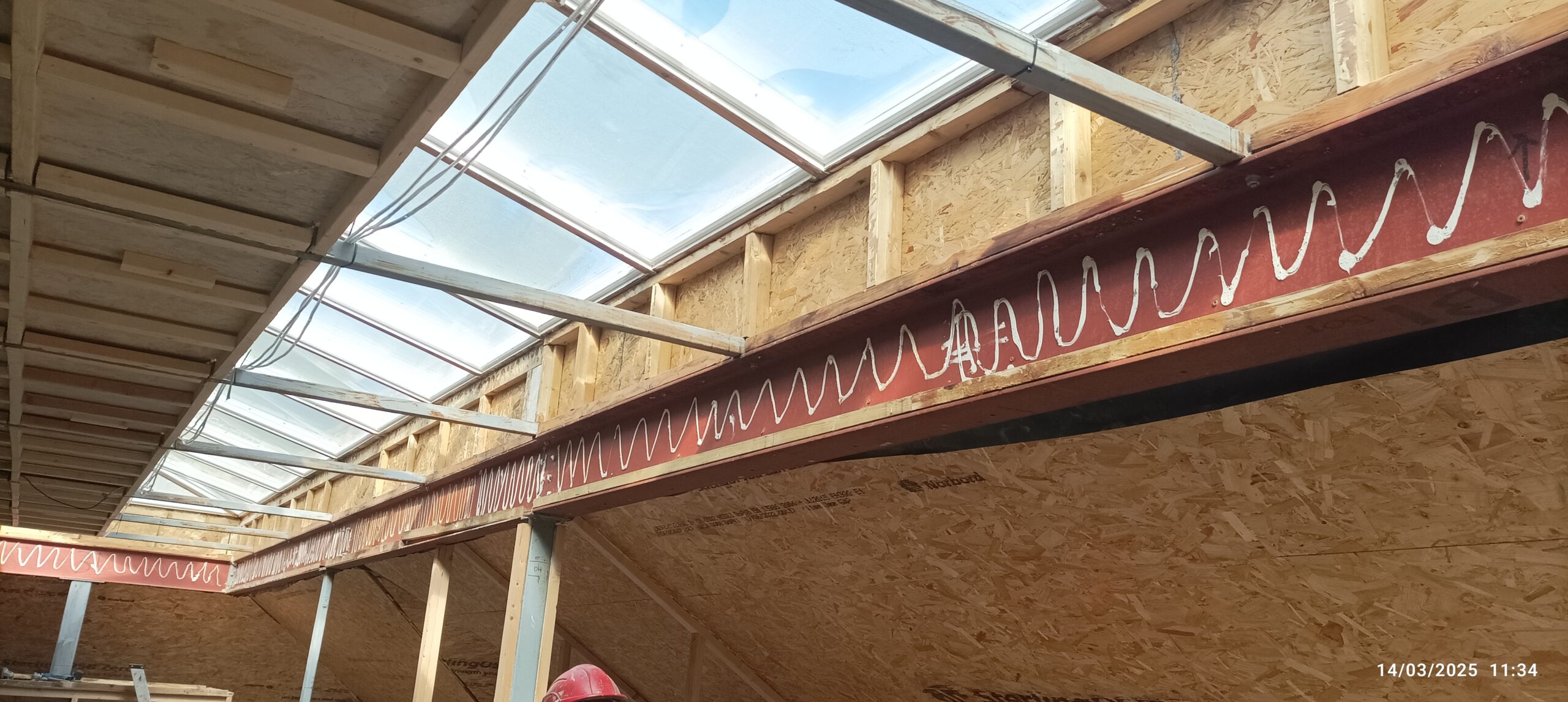
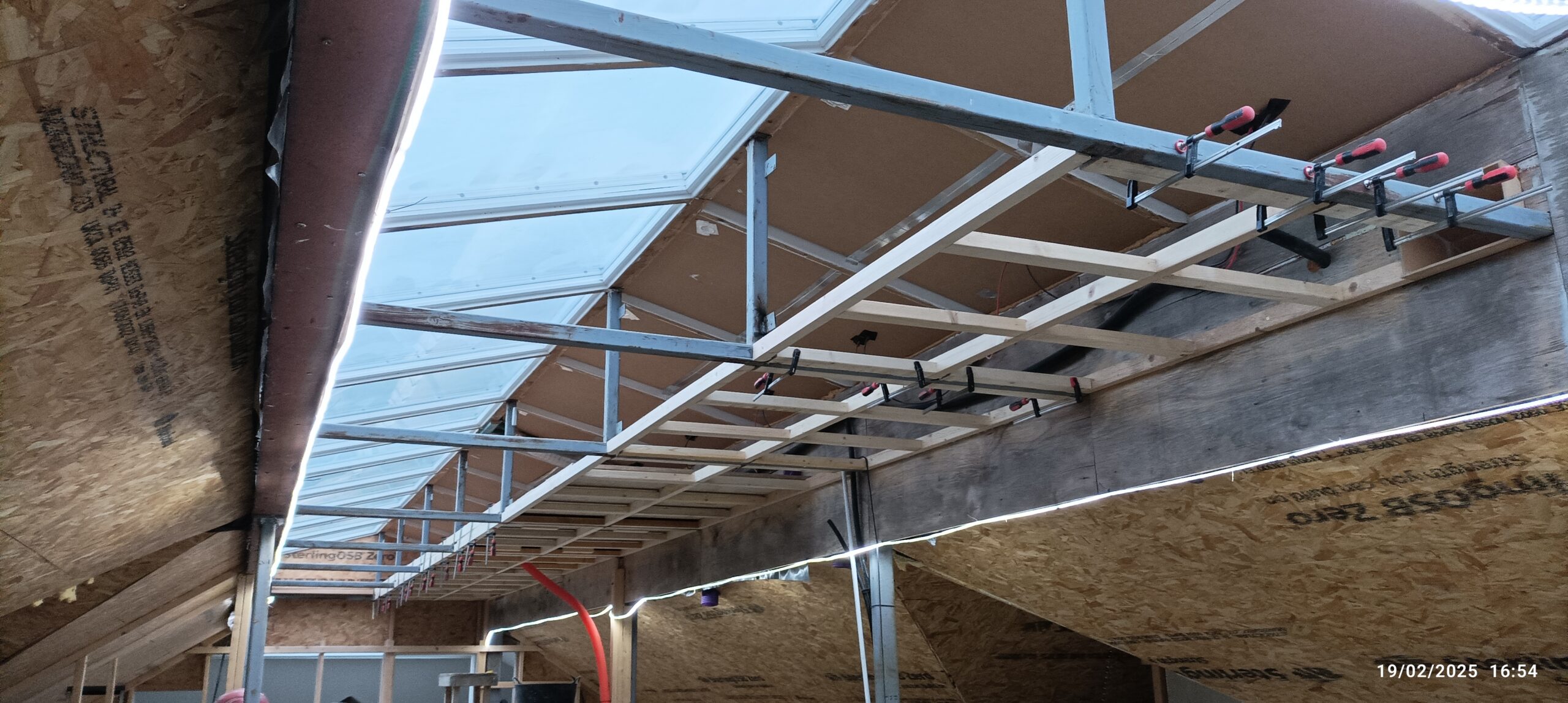
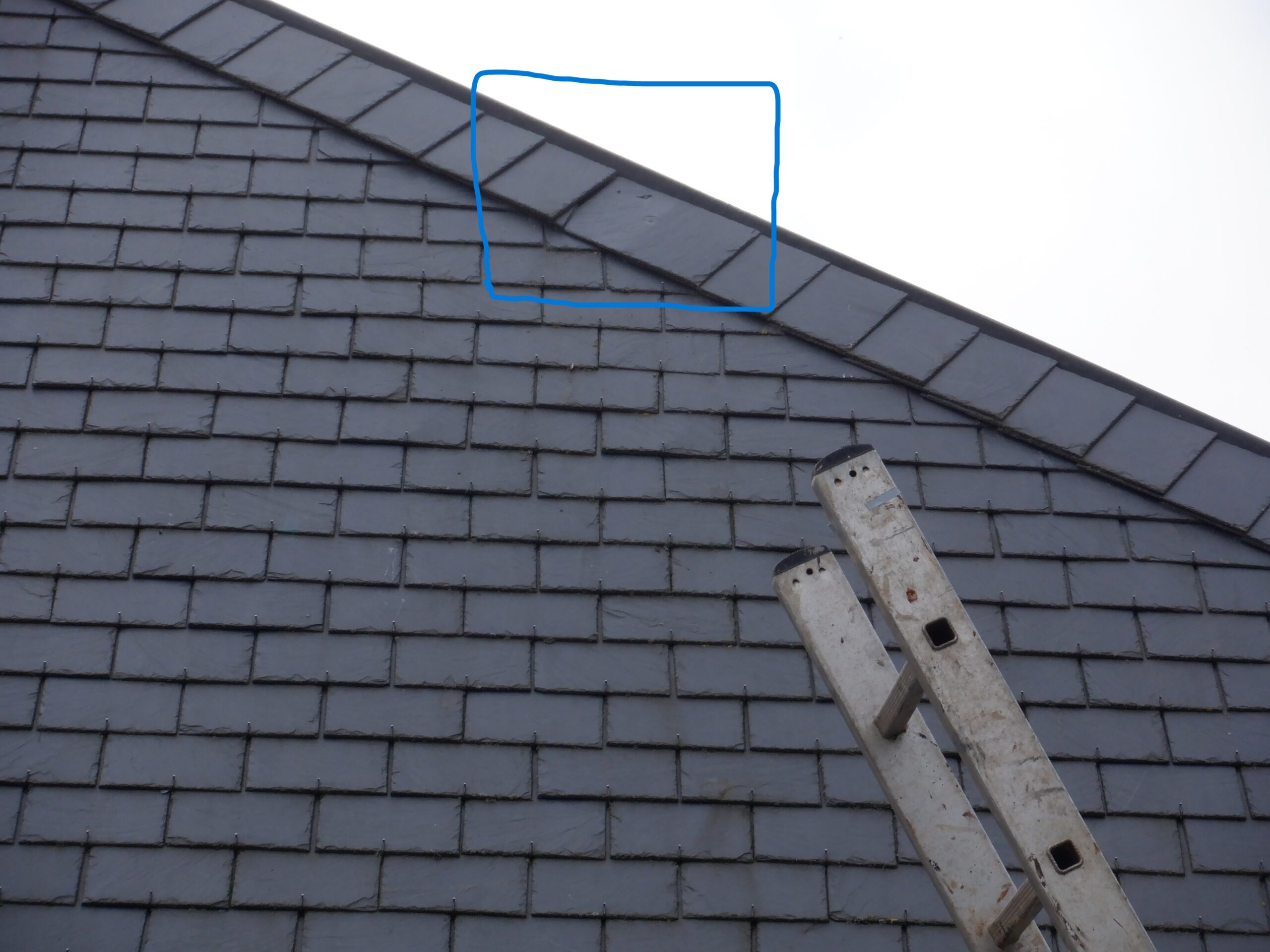
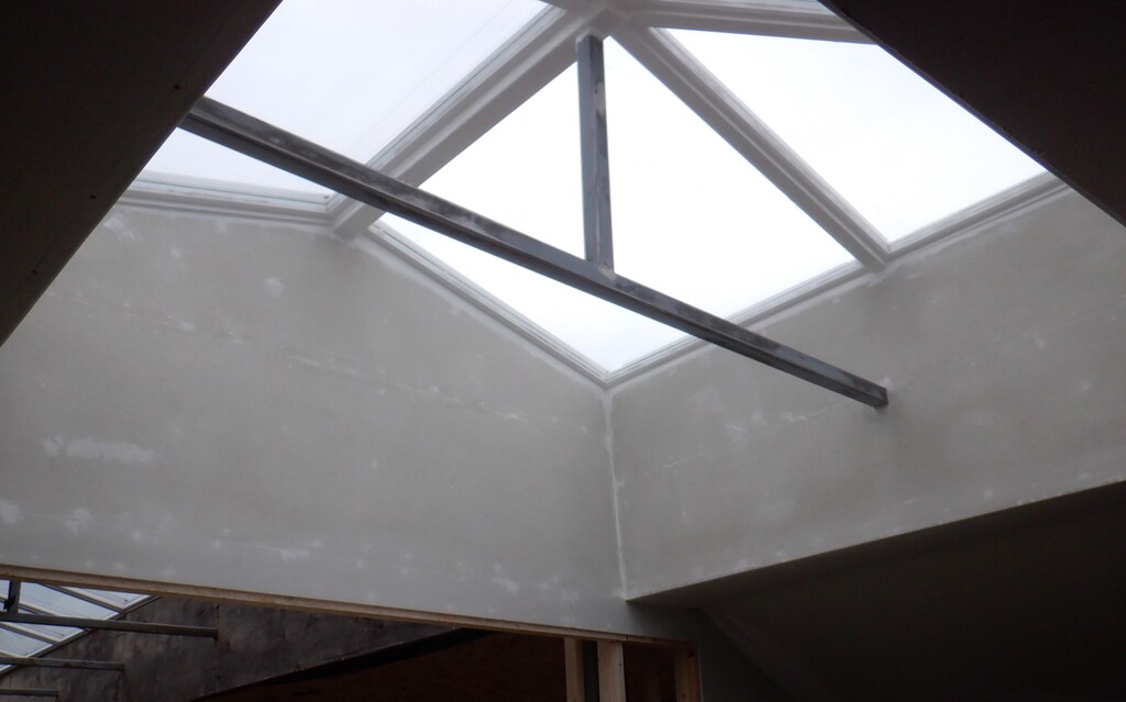
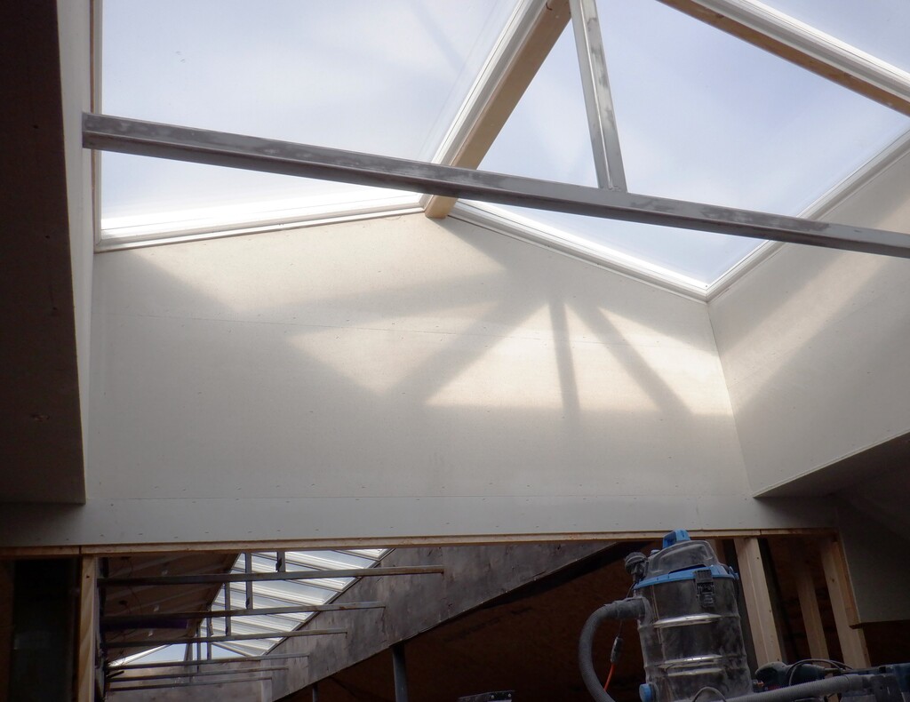
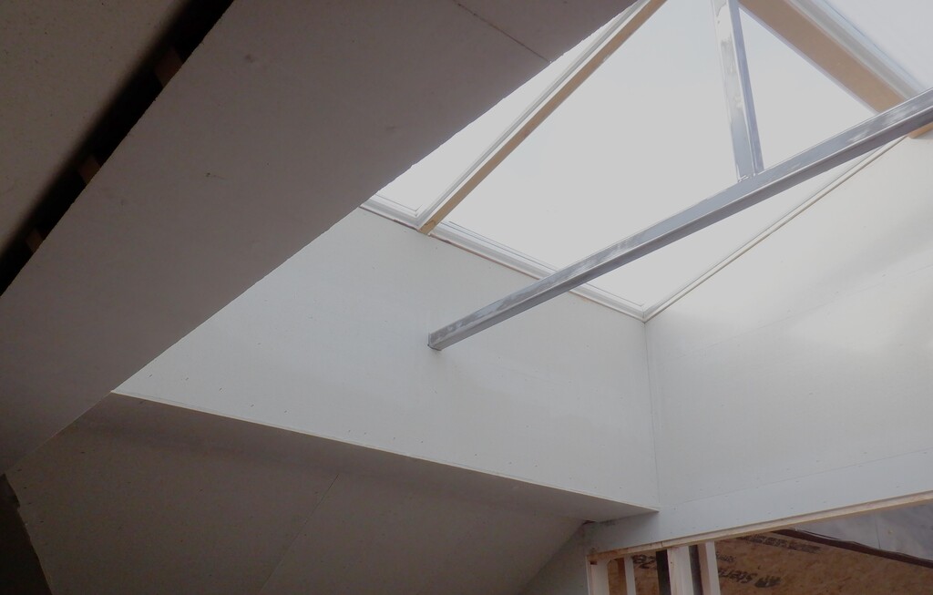
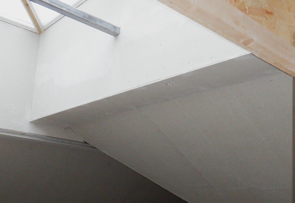
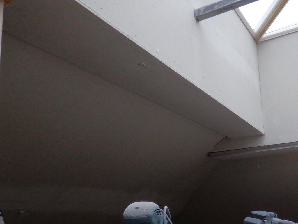
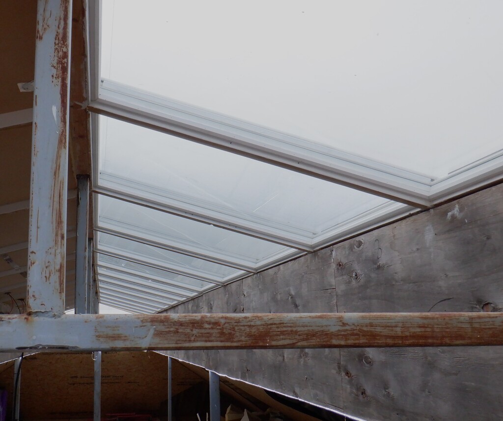
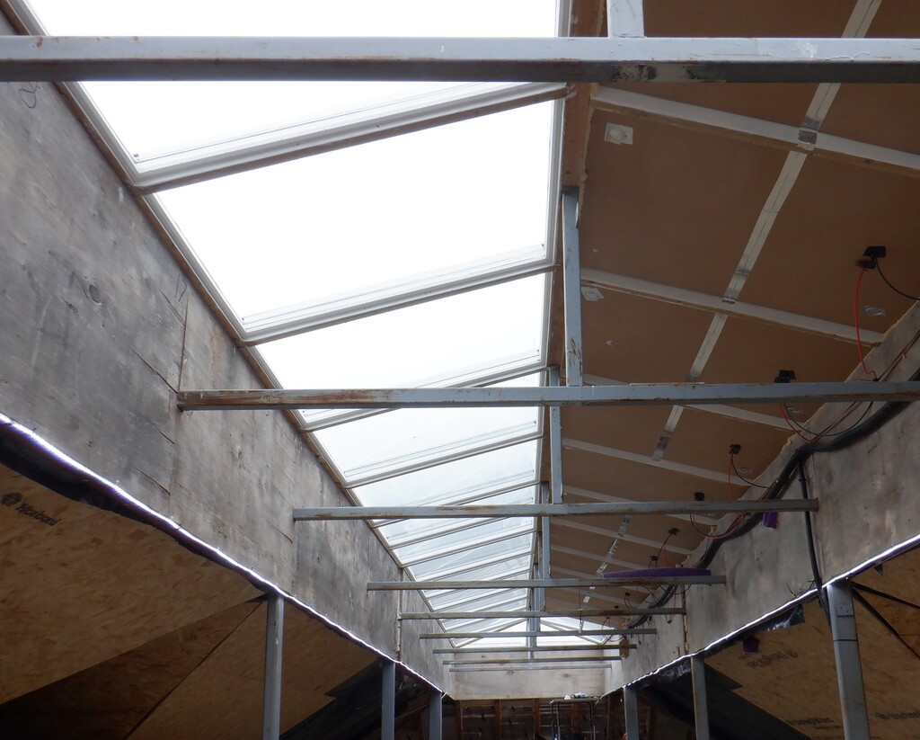
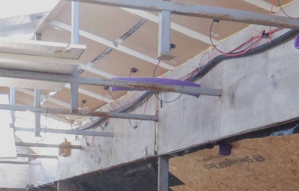
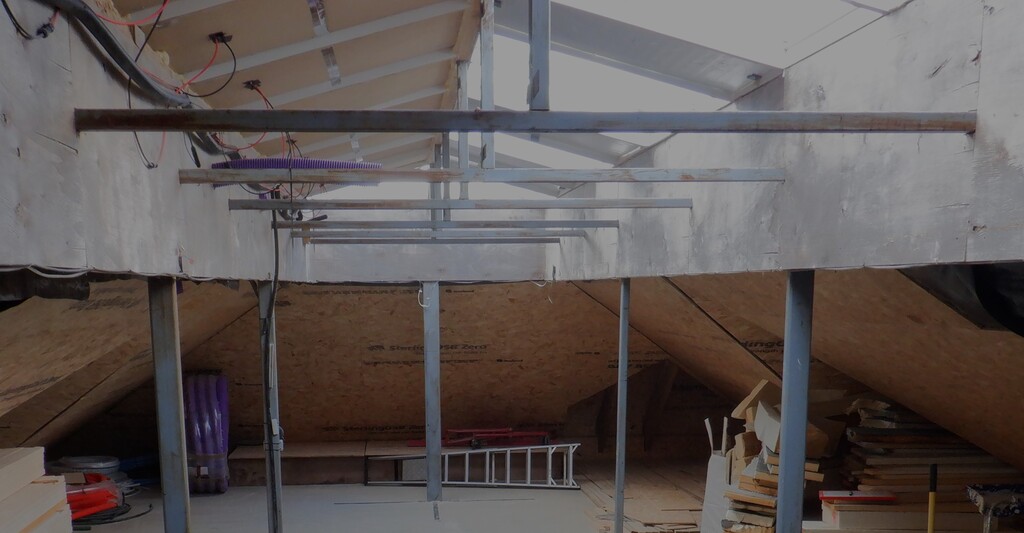
    Just to recap to what we got up there in the Skylight, is a 50mm square steel beams going across from one side to the other side, that supports a similar 50mm square steel post going upwards which has the wooden ridge beam running on top, supporting the Skylight Windows themselves. These steel beams will define and form the basic shell, or box, to cover up the solar panels, to hide the air ducting and provide somewhere to house the Window Blinds and lighting units as well.

    So, we needed to construct a wooden framework that goes from one steel cross tie, to the next cross tie. They are like upside down capital T. But, in order to attach the wooden elements to the steel, there needs to be metal tabs welded on to the sides of the steel tube. We already had two pairs of tabs going up the vertical post, ready to take a 38mm thick CLS timber, but, we needed two more pairs of tabs to take a 50mm thick piece of timber, this thickness matches the size of the steel tubes. These pieces of timber will support both the layer of OSB boards that is going inside the boxing, sitting on top of the steel frames, and also to allow the plasterboard to be glued and screwed upwards, to encapsulate the steel bars from underneath. Both surfaces needed this timber framework so that we could screw the materials in place quickly, without having to resort to wet slow drying glue as the sole fixing method.

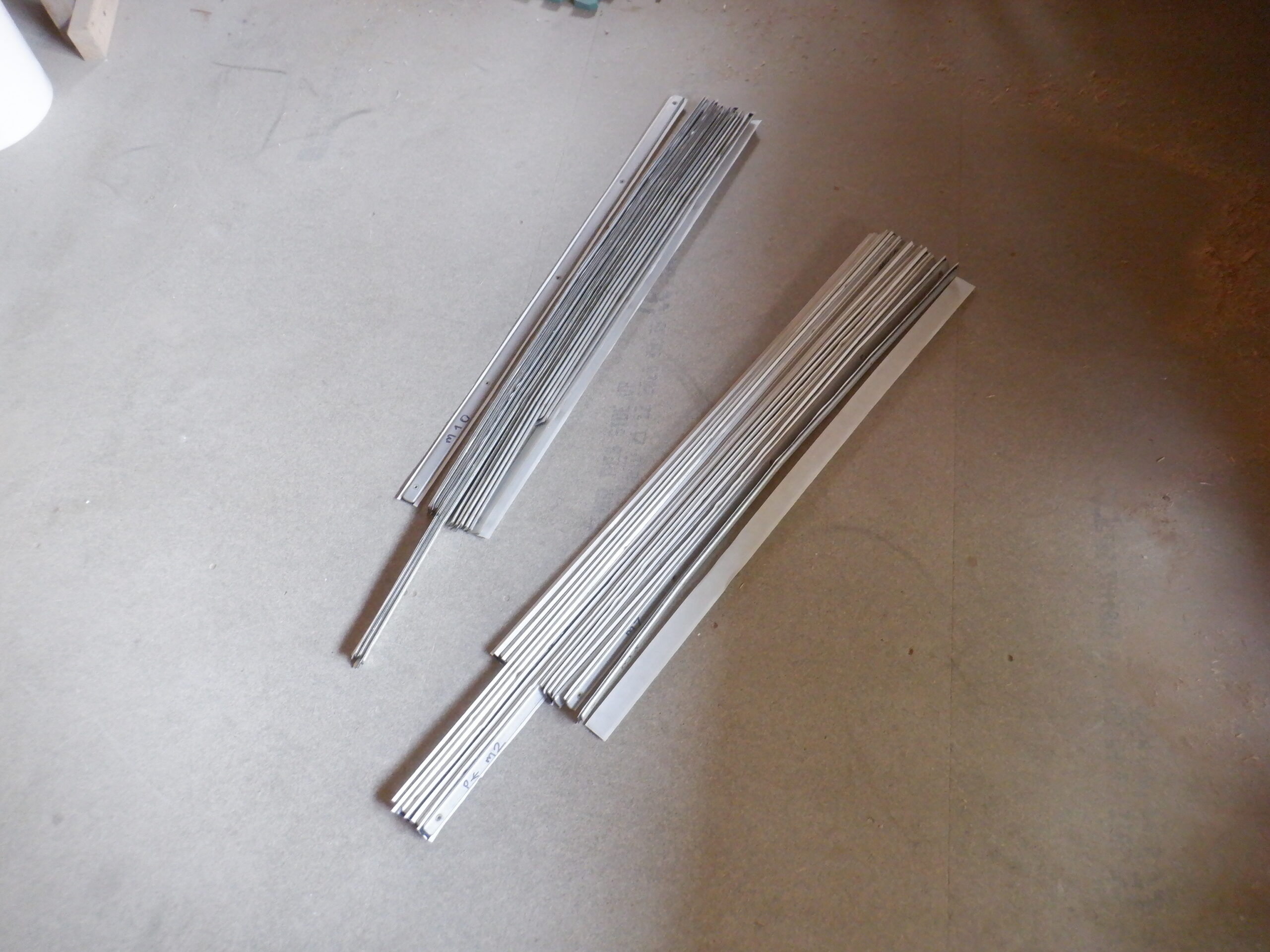
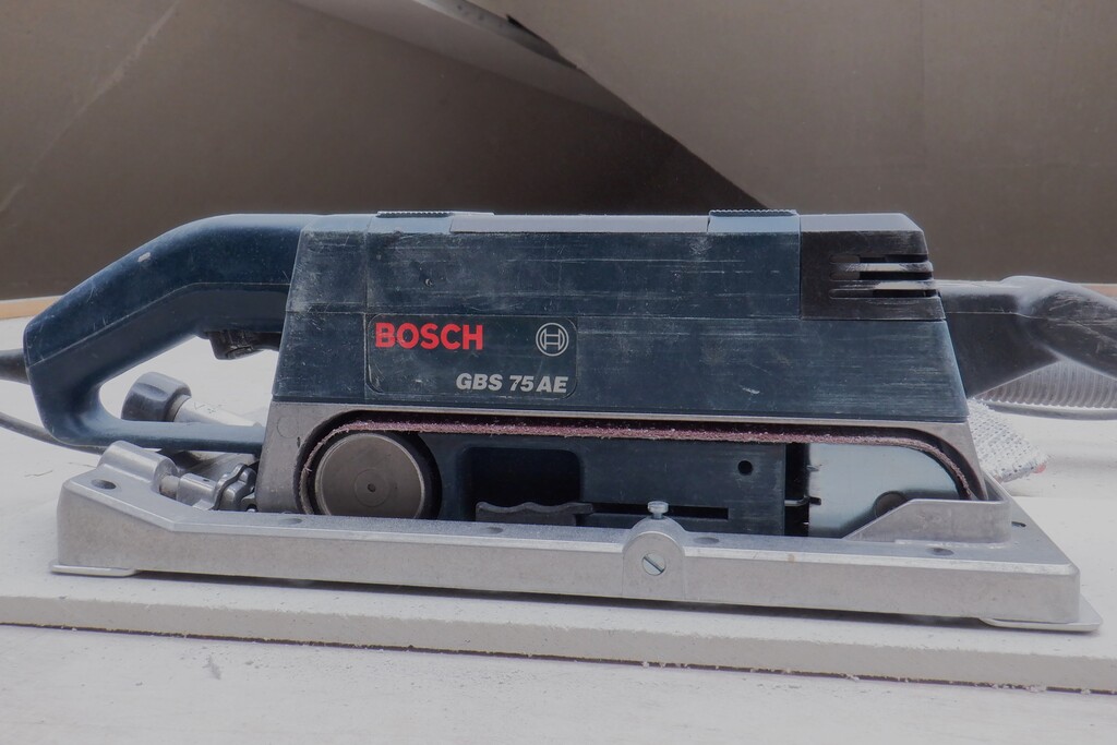
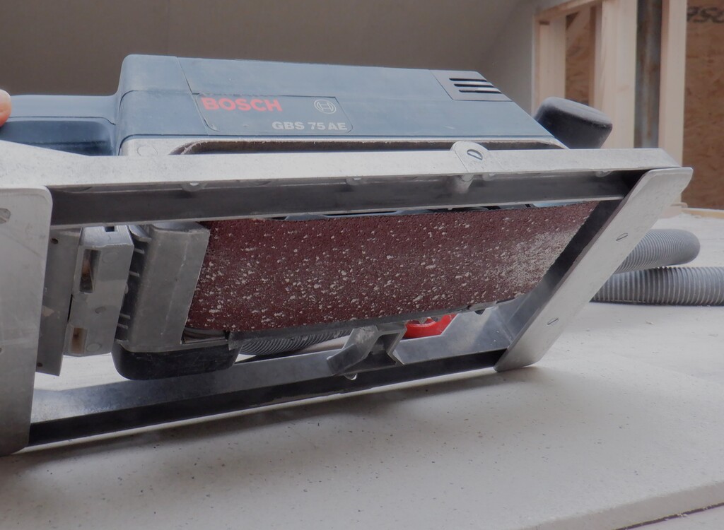
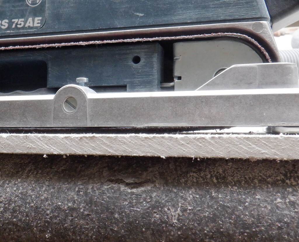
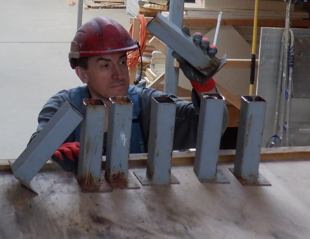
    So, we needed twenty-eight more steel tabs. We looked on our steel material rack and found a strip of 5mm thick bar measuring 70mm wide and we did sliced off twenty-eight pieces, measuring 48mm long. We did have to run our belt sander all over the steel bar because it had a rather gritty coating of rust, and after we had cut the pieces, plus drilling two 4mm holes, we put them all in a solution of anti-rust liquid and hung them up to dry on a length of string, like a necklace!!

    There are seven sections that needed these extra timber pieces spanning the gap between the ties, varying from 1495mm, 1520mm, 1595mm and 2140mm. We found the straightest 63mm CLS planks and created seven triplets. We did add an inch to the lengths, just in case there were local variations. All the timber pieces were taken to our table saw and proceeded to slice them down to exactly 50mm wide. We now have a heap of 12mm thick thin strips which probably will be useful in some future job!

    Before we can fix these pieces in place, we had to weld our new tabs on to the side of the horizontal steel tube. The first one is positioned in the middle of the steel bar so that the wooden piece will go aligned to the front surface of the vertical steel posts. This is where we will put our plasterboard sheets on that flat vertical plane. The second tab is just approximately half way along the tube heading towards the edge of the Skylight, so we had a template to position that second tab consistently on all sections. We moved the platform along to do each section. We did have to design and build a mobile welding station, with drawers etc. see  Building Welding Station. It made things so much easier in having the welder close to our work.

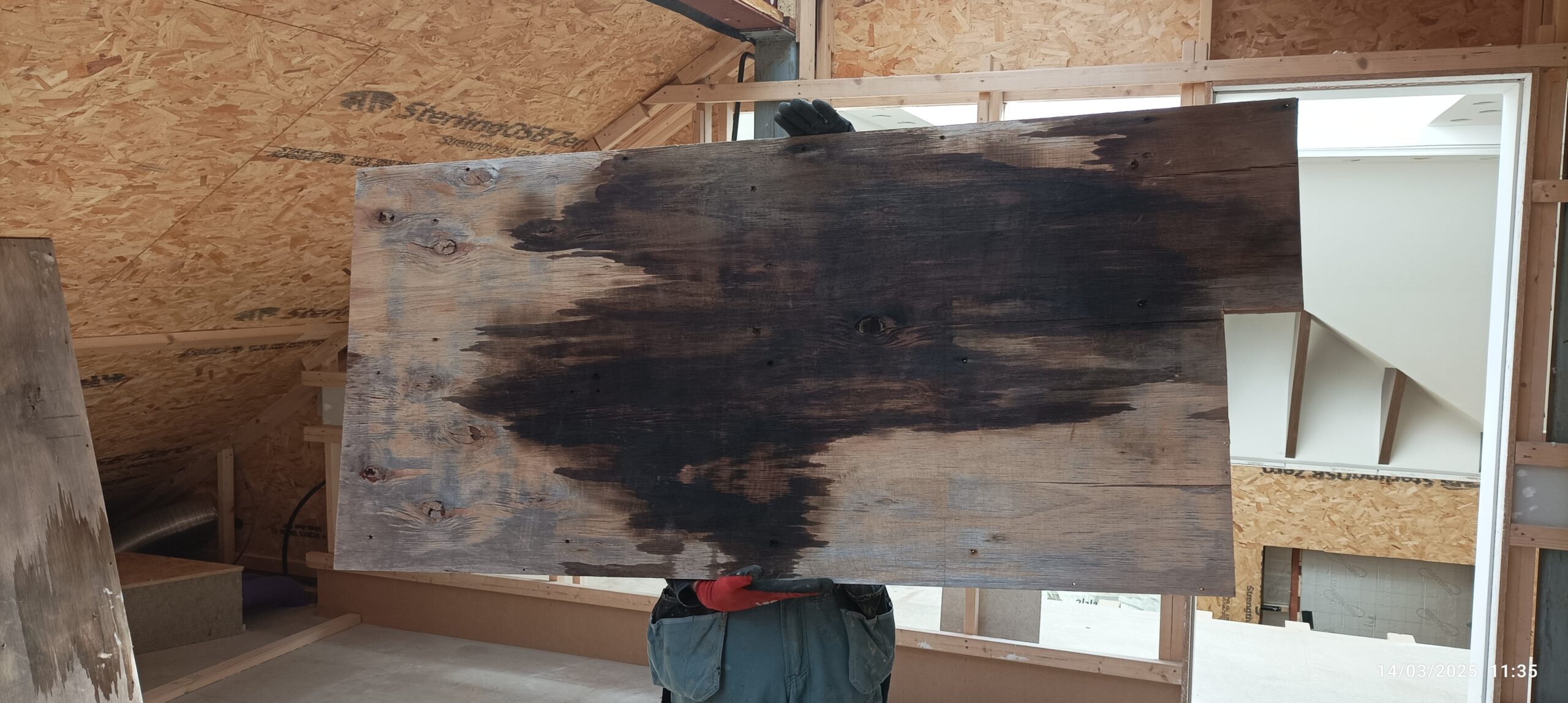
    Now, back upstairs, with our pile of 50mm by 38mm pieces of wood, we went along gluing and screwing the three pieces in each section. The first one on the front, glued and screwed into place, making sure that the alignment was good, followed by the second one in the middle, and finally, the third planed piece of wood is glued directly on to the plywood surface using PU construction glue, and screws to anchor it down while the glue sets. The plywood surface was thoroughly sanded using an orbital sander with a rough paper loaded, to get rid of the weathering.

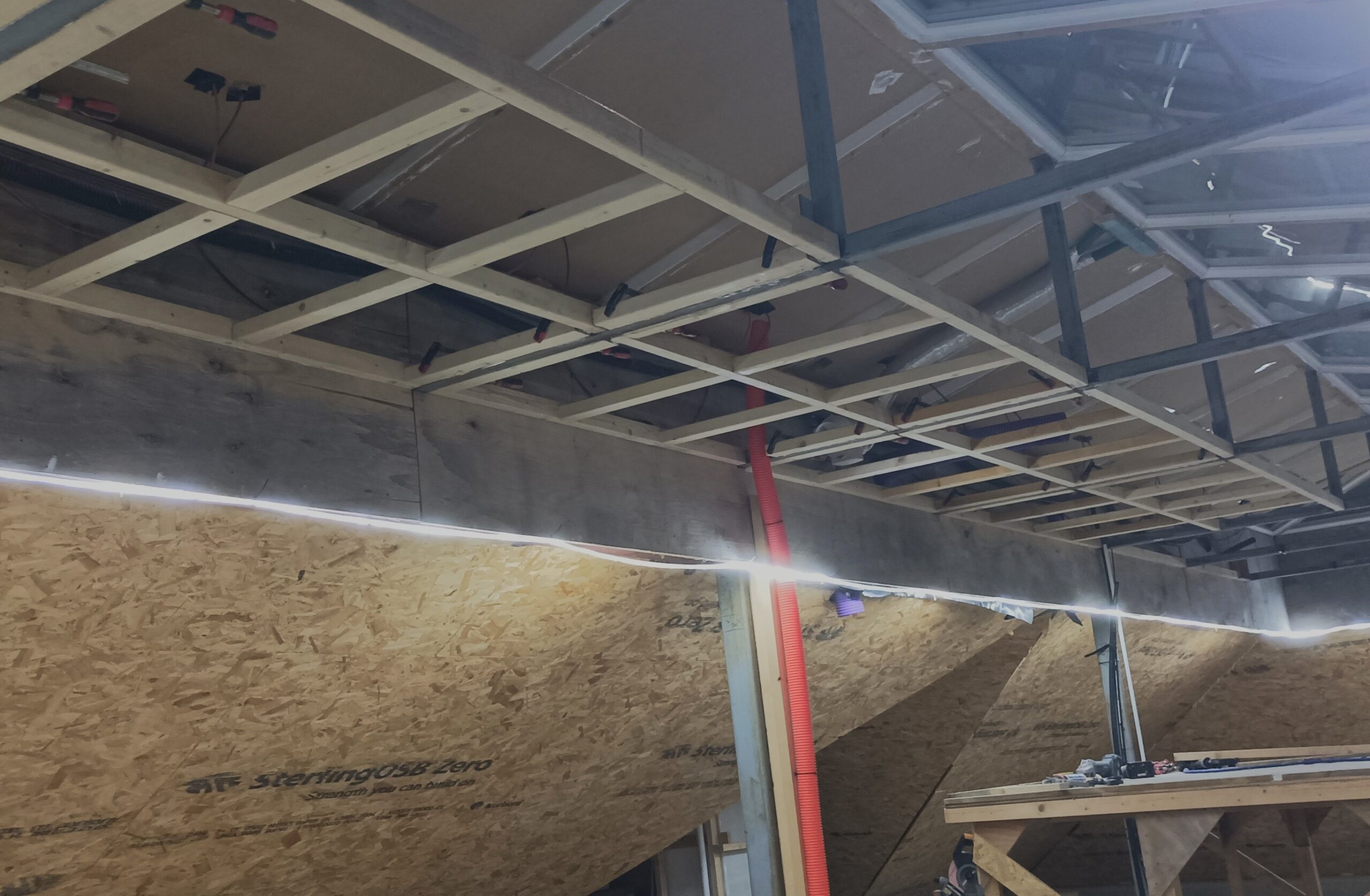
    While we are in a section, after we had put in the three pieces, we also put in four short lengths of 63mm CLS pieces, flat, going right angles to the other framework, to join them together and provide a flat surface for the plasterboard to be glued and screwed into. Without them, the plasterboard is not strong enough to be supported 600mm from joist to joist. Hence these extra pieces being glued and nailed into place.
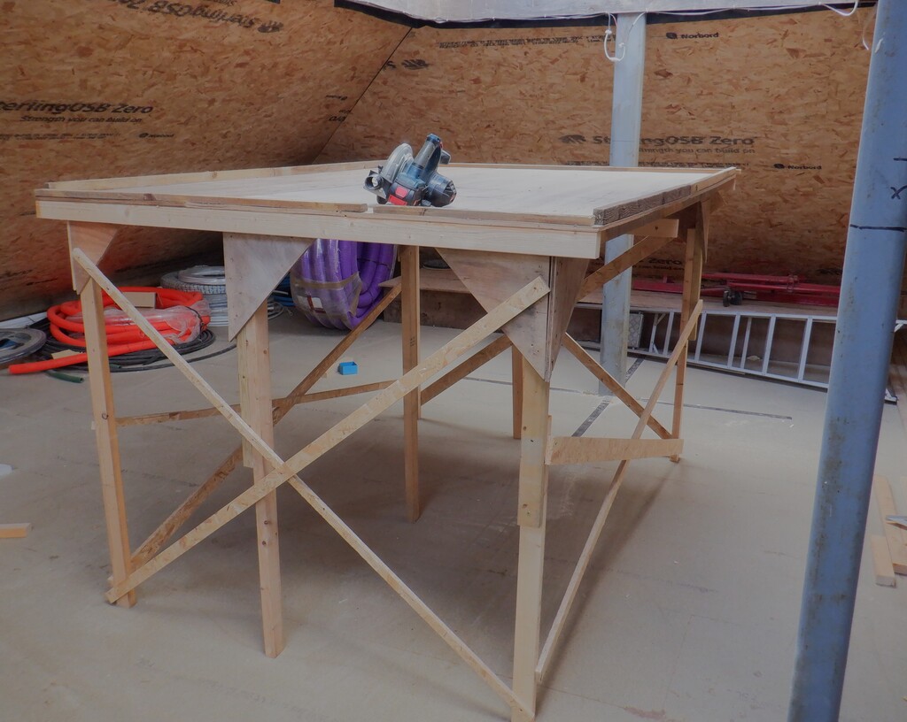
    Skylight Base Frame

    Skylight Base Frame

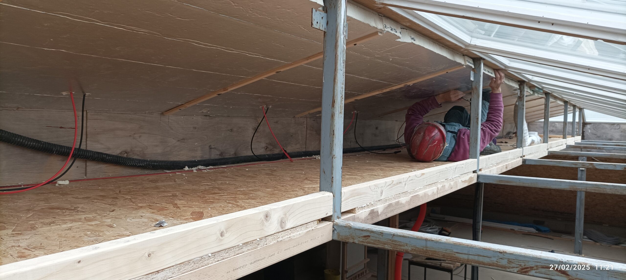
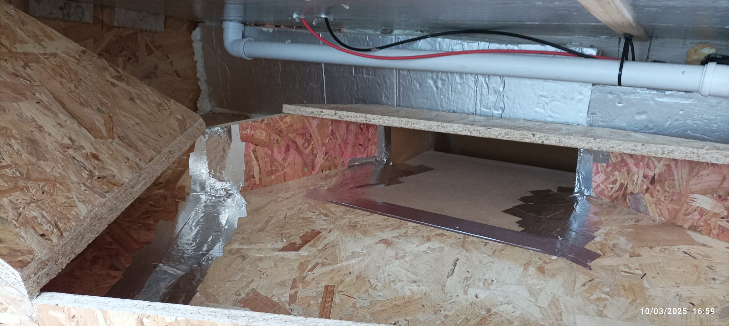
    Now, we proceeded to haul up sheets of 18mm OSB board pieces. We had a pile of already used boards and they are a bit painty with white emulsion. These came from the time we had built the temporary platform when we were constructing the ceiling and Gallery in the Great Room. There were eight half boards and one two-thirds sheets and turned out to just fit the entire length of this new boxing, a total of 11660mm end to end!

    We had to cut notches in each board piece, to go around the steel post, also wide enough to avoid the two metal tabs as well, when we lower each sheet into place. It got the usual PU glue and dozen screws to fix it down tight. The first three sections working from the Great Room end, had the board trimmed by about 30mm and the final four sections, had only 10mm bit sticking out to be trimmed off.

    Next, we put in the first horizontal CLS piece that is sitting on the newly created OSB floor, all glued and then screwed using the metal tabs to anchor it. This helped to stiffen up the framework very nicely.

    Skylight Frame 2

    Skylight Frame 2

    by this time, our delivery of eleven sheets of PIR insulation 50mm thick boards had arrived. This type of insulation is the modern version of the old PU foam and offers a much better fire safety response. PIR stands for PolyIsocyanuRate and it is only slightly worse thermal properties than PU foam.

    We needed this insulation boards because we need to protect our house energy where the solar panels are situated as there is no double glazing etc. So, we went along underneath each solar panel section, there are eleven of them in all, and cut an almost square pieces, measuring 1040mm wide by 1170mm high. We had to create a template to locate the four holes (two air holes for cooling down the solar panels, and two smaller holes which has the electrical cables coming through) and using this template, we could drill out the holes and insert the foam sheet up into place. It was a bit fiddly at times, and one of our solar panels had a different positions for the air holes, but, we made it all the way along. We then repeated the process again for the second layer of foam boards, this time anchoring the sheets up by using a strip of 12mm thick CLS left-over pieces and screwed them up to grip the edge of two boards with four screws. Finally, we used the left-over pieces of foam, to stick on the plywood panels at the back of the compartment which improved our house insulation a little bit.

    Insulating Solar Panels

    Insulating Solar Panels

    Now that we got up the insulation panels, we reconnected the cables from the eleven solar panels and tested each one to make sure that all eleven are still working. BUT, No! The first one (nearest the Great Room end) was not working. It was reading zero volts! Oh No! This meant that we had to undo the two layers of the 50mm thick foam pieces, unscrew the MDF 6mm thick board, to gain access to the solar panel itself. Then, we could see that the wire coming from the back of the solar cells and going into an adapter box, the soldered connection was very poor so we used our gas powered soldering iron, with fresh solder, and we got the wire solidly resoldered much better this time. We now have proper amount of voltage coming down the wires, some 20volts since it was a bright sunny day. We reassembled the cover, and the foam pieces, clamping it back down again.

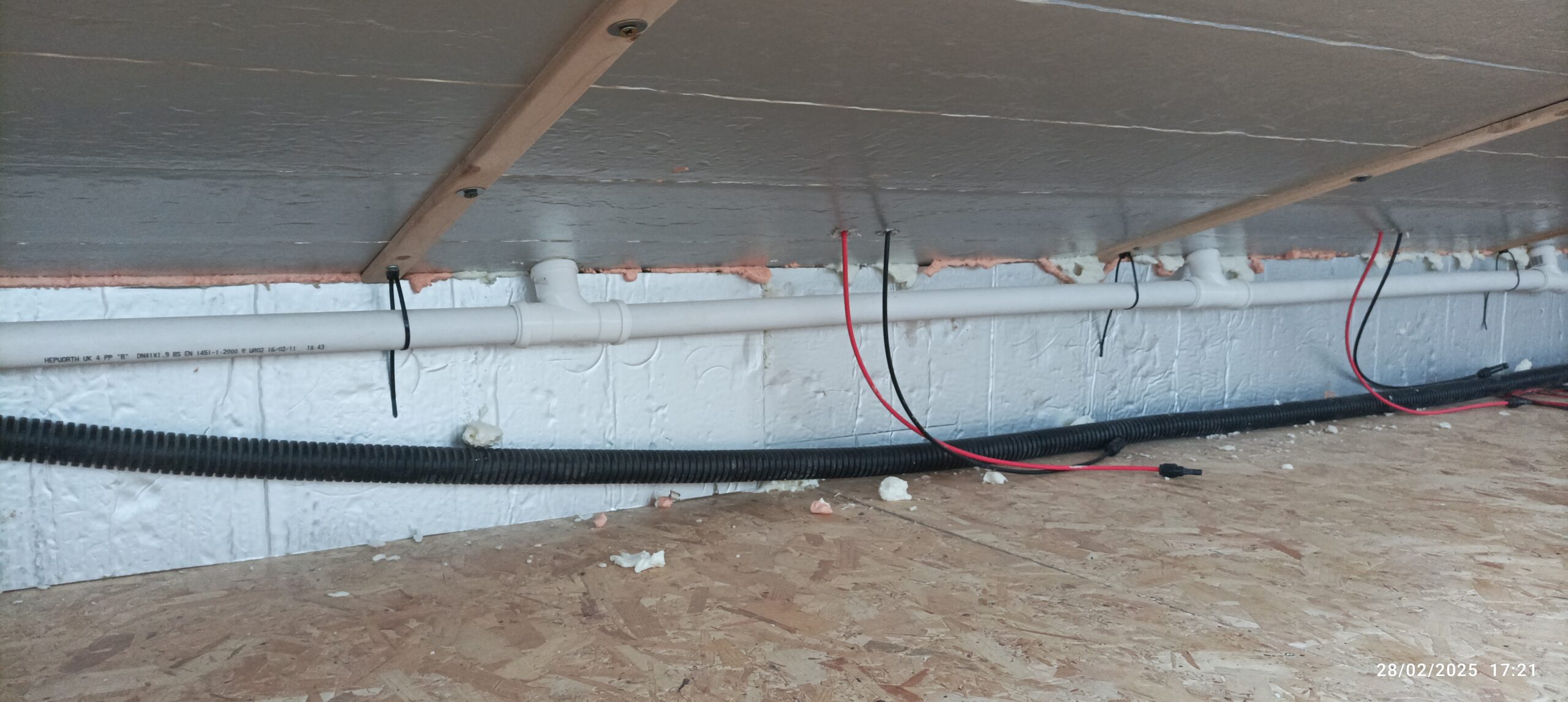
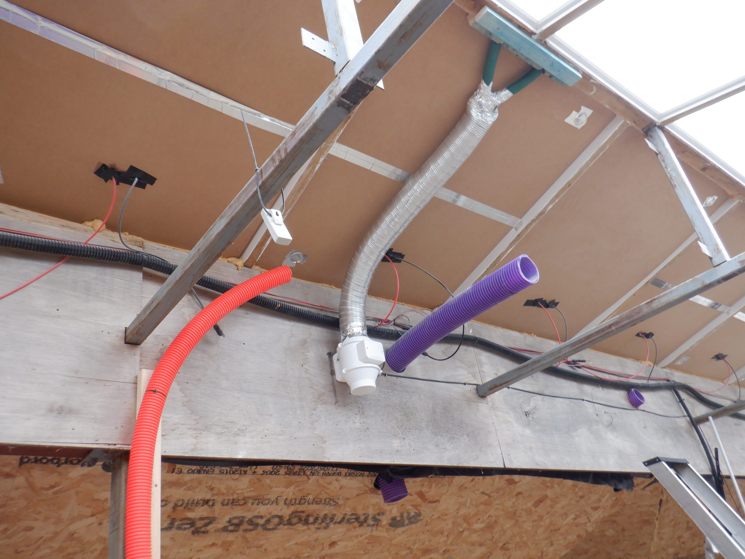
    We next tackled the task of installing an air supply to the Solar Panels, at the bottom, using 40mm diameter white plastic plumbing pipe, with push fit T-junctions for the middle nine panels and right angle bends for the outer two panels. We are planning to have air supply coming up from the main air duct running downstairs underneath the hall, going through a 50mm flexible conduit and that terminates into a switching chamber where the air can be diverted to either the Solar Panels to cool them down during sunny periods, or, through the gap above the double glazing to control the condensation. The cool air will push the hot air out via the upper air hole and will be taken away via several valves on the air duct that we got running inside our Skylight Box.

    Air to the Solar panels

    Air to the Solar panels

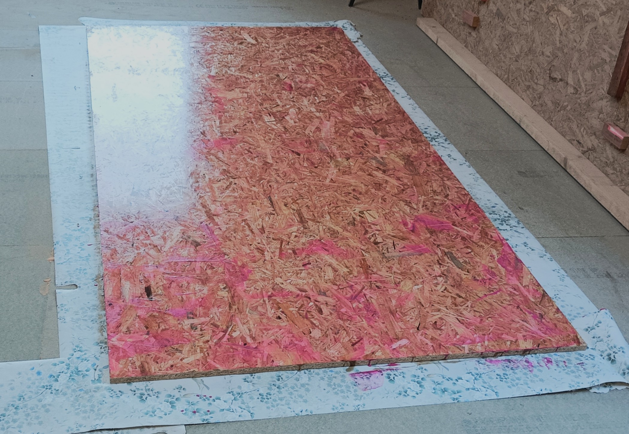
    Talking about our air duct, that is what we did next. We took three sheets of 18mm OSB boards, laid them out on the floor in our Great Room and proceeded to give them a double coat of polyester resin, to give a smoother finish, filling in all the holes in among the strands of wood, plus also to prevent moisture to build up in the fabric of the wood as well.

    Varnished OSB

    Varnished OSB

    Then we sliced up two of those boards, into eight 150mm wide strips from the first sheet, and then eight 300mm wide strips off the second one. These will form the main duct running along the whole Skylight Boxing, fitting just nicely in between the two “chimneys” that will take the waste air away. We fixed them using small pieces of 25mm by 38mm battens, using three of them on each 150mm high 8foot vertical sides, gluing and screwing them into place. We used the 300mm wide lids as a spacer to position the second line of battens at the back. We had previously set our green laser line generator to give us a ruler straight line for the front side of the ducting. We marked the surface with lots of dashes.

    Next, we looked at the beginning of the ducting, the furthest end away from the Great Room, and designed a gentle curving duct that flows the air around ninety degrees and also to bend slightly downwards. It also had to squeeze the air a little bit, to fit the chimney hole itself, before it spreads out in the channel down inside the sloping roof, to the main duct running around the first floor.
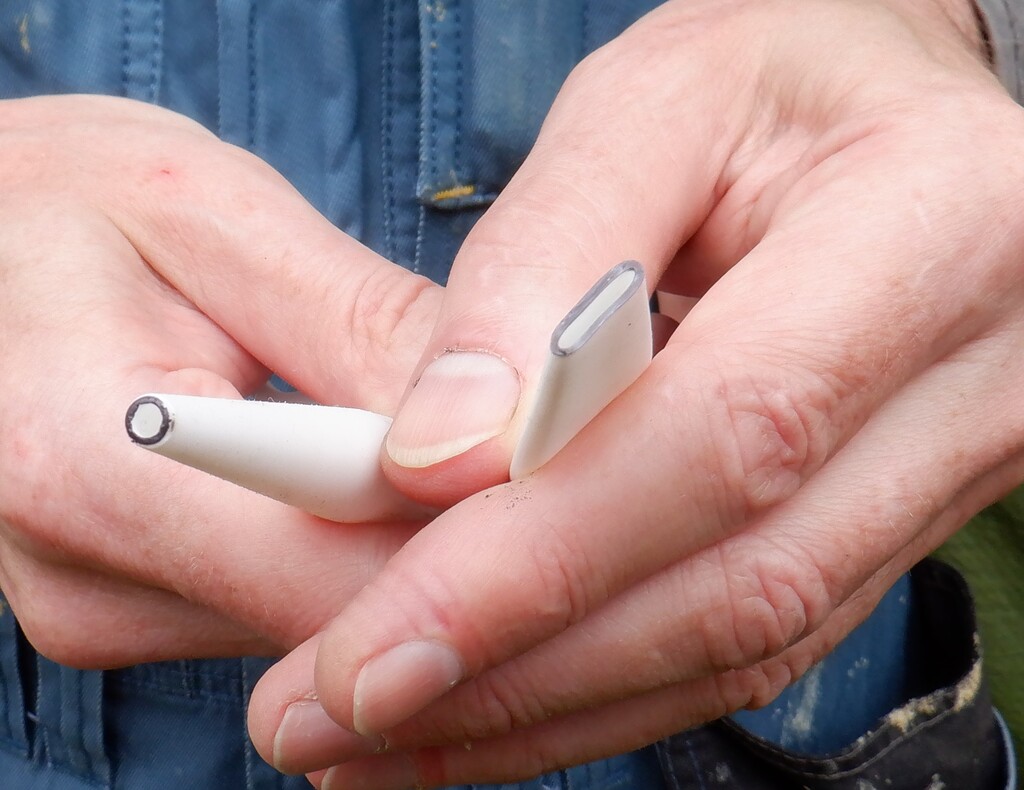
    We used a piece of our 1mm thick flexible plastic to provide that gentle curve, to encourage the air to flow around the bend smoothly. We then finally put on a lid to cover everything up. Eventually, all these joints will have aluminium sticky tape to seal against any leaks etc.

    Next, we proceeded along the length of the ducting, to drill holes into the lid and sides, to screw in a captive nut, and then screw down the lid with steel bolts. We used all eight of our 300mm wide by 4foot length pieces.

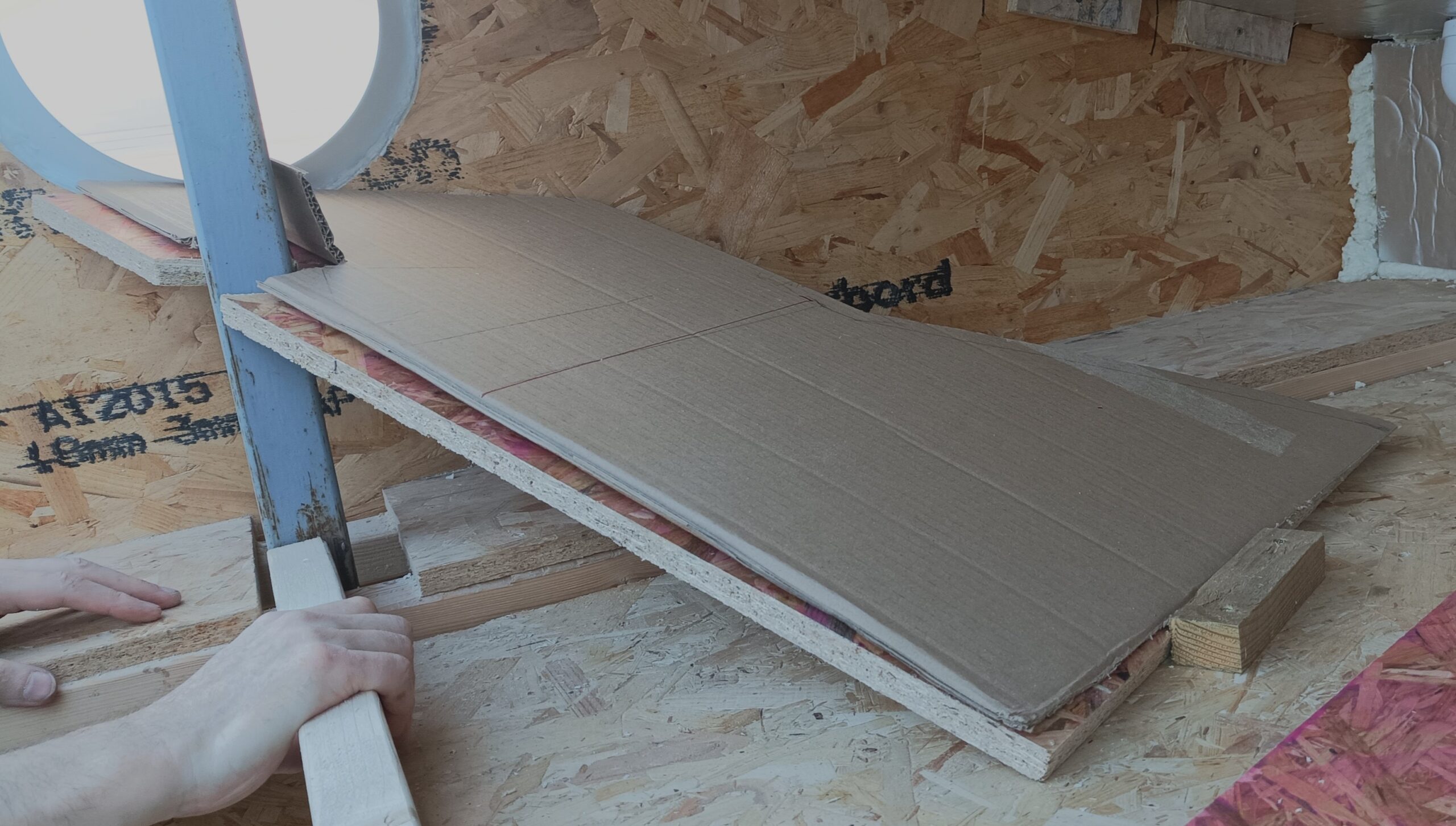
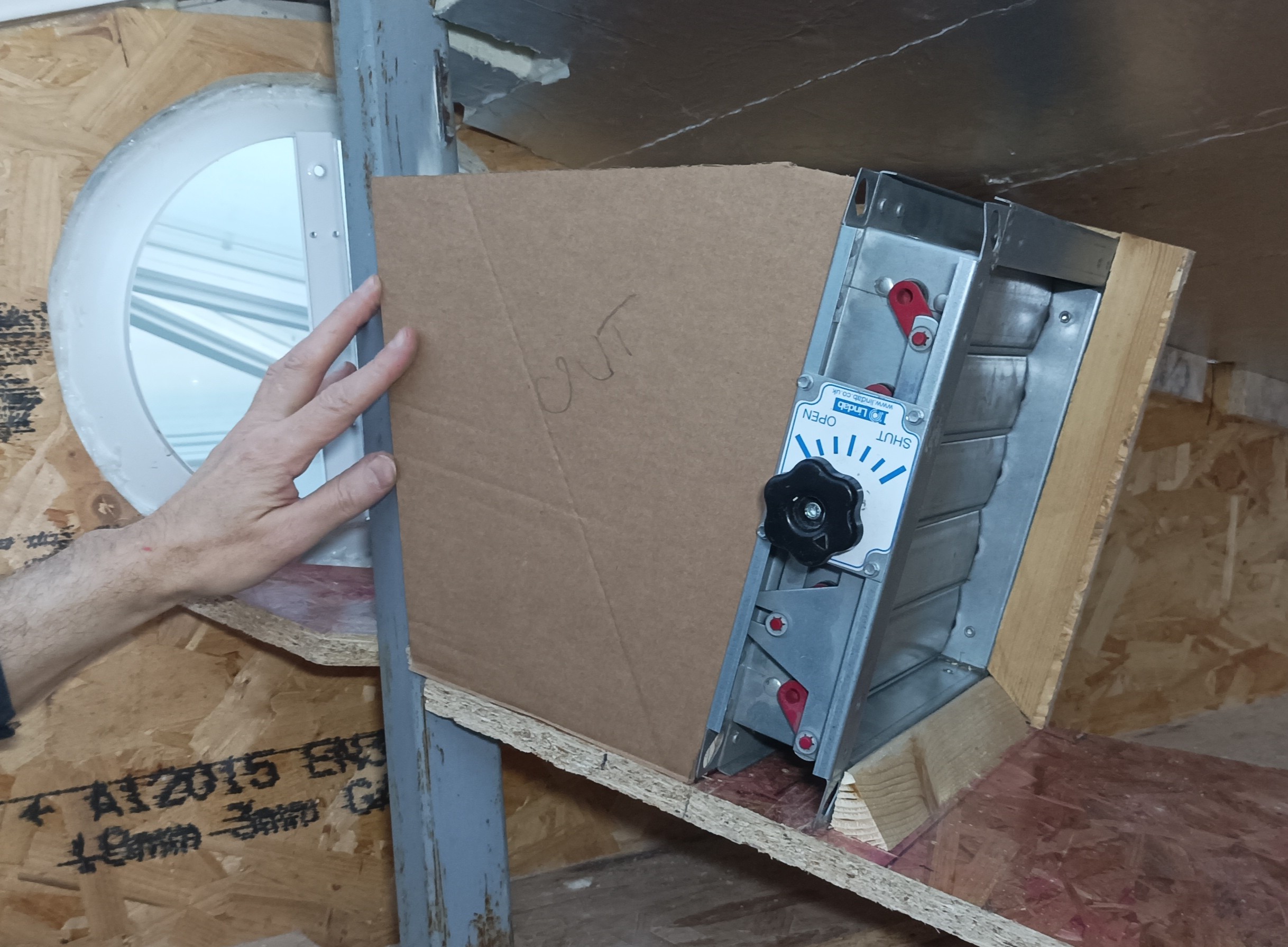
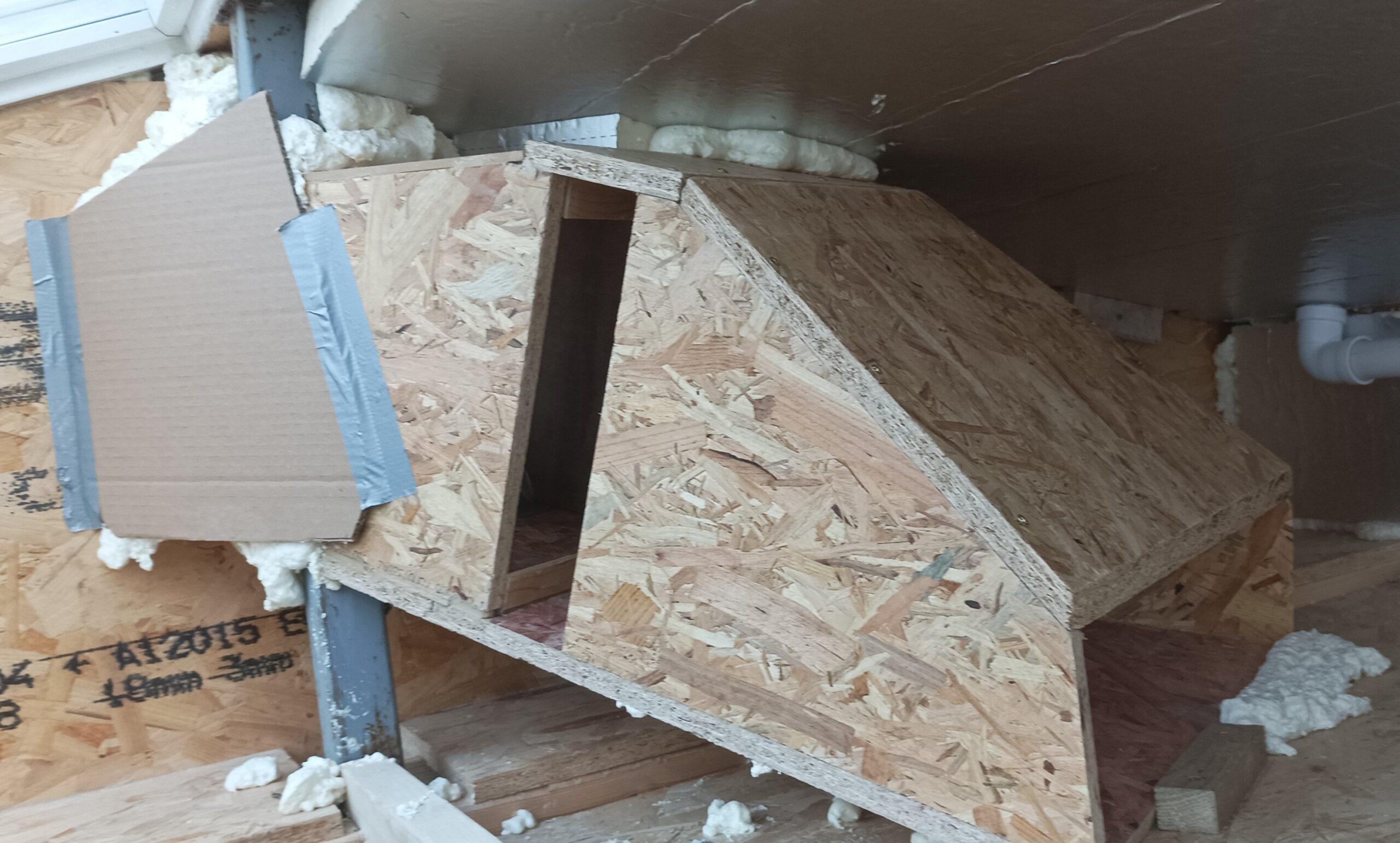
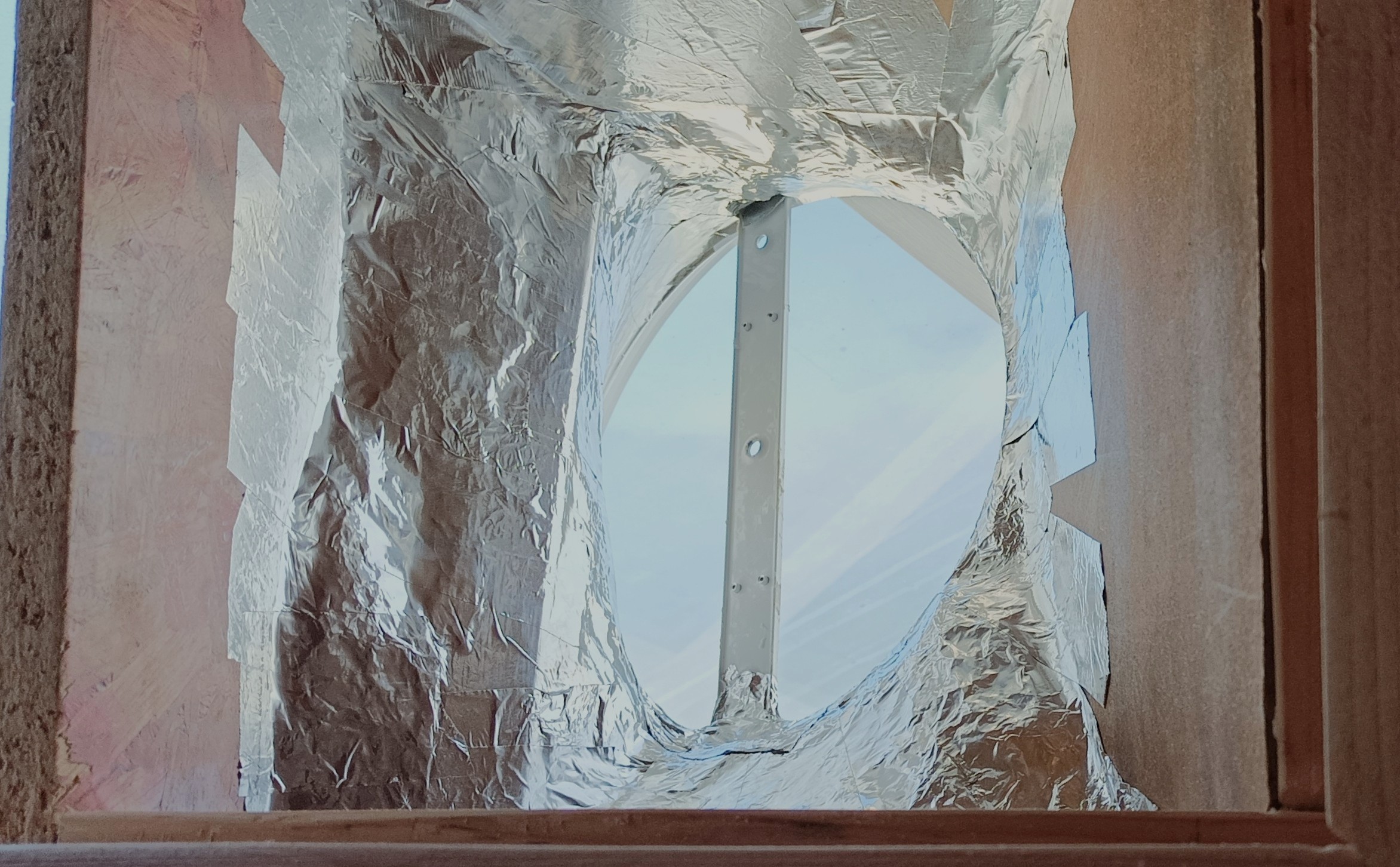
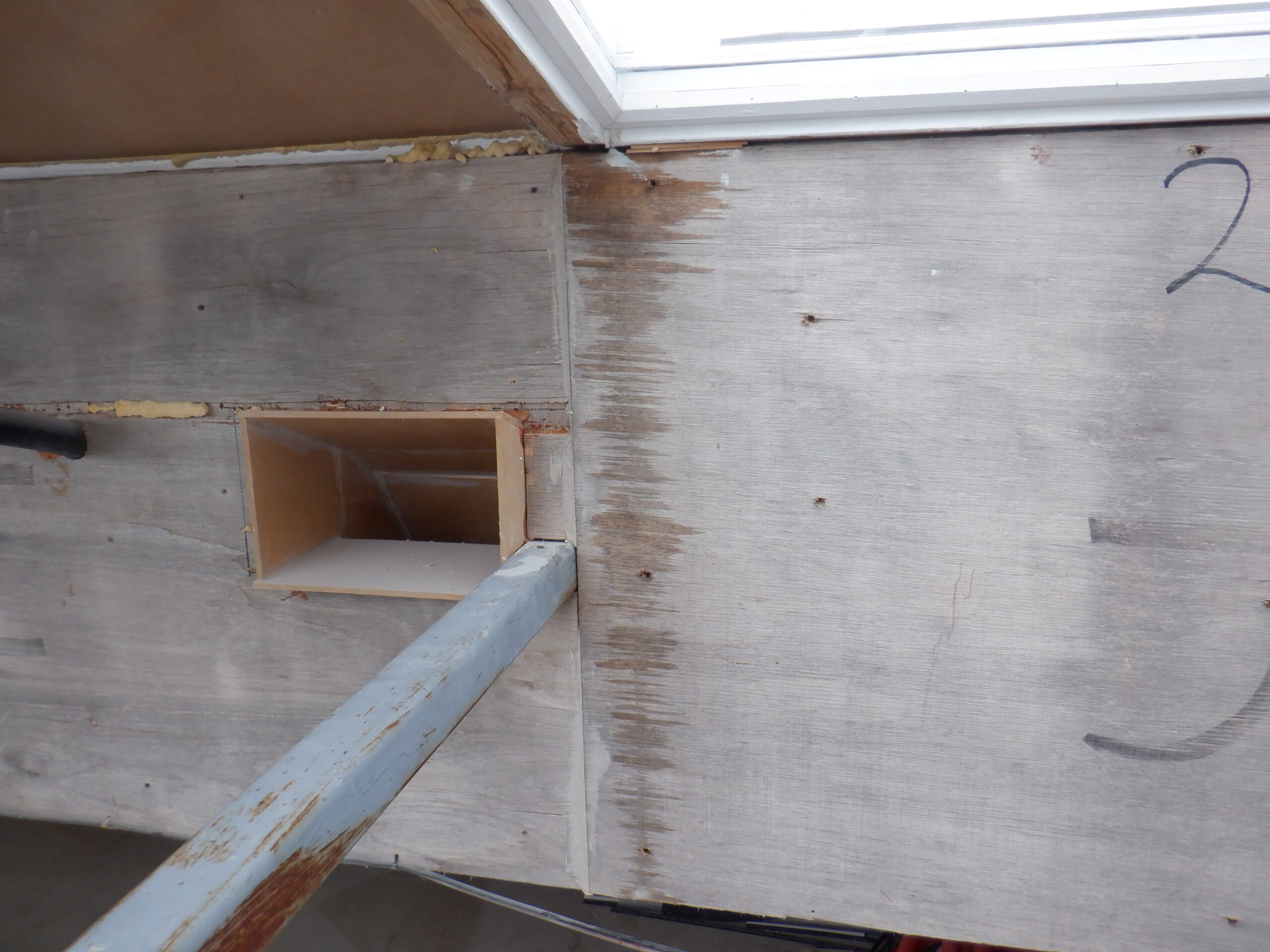
    Now we are at the other end of the duct, there is a far more complicated situation to deal with. As well as the chimney to connect to, we also had a large round vent to connect with, this being the vent for the Skylight inside the Great Room. It was a case that this 250mm diameter circular vent is positioned in the middle and we had a metal square post only a few inches away. Plus, another issue was that we needed to have a valve somewhere near by to control the amount of air being drawn from the Great Room. This louver valve is square, also 250mm internal size. Furthermore, the round vent hole is much higher than the rest of the ducting so indeed, we had to design a sloping downward construction, incorporated that 50mm square post, pass through the gate valve and then squeezes down and widens out to join with both the main duct running down the Skylight Box and also to the chimney. After careful measuring and thinking about shapes and angles, cutting pieces of cardboard to test things, we finally got a wooden square like object, with extra bits and pieces to help convert to the round shape, plus lots of spray PU foam, to allow us to rasp the hardened foam material into a morphing design to transform from that round hole, to roughly the square ducting. We then covered up all the foam, which is rather rough, with lots of aluminium sticky tape which has a very smooth metal finish. We also covered up the other joints and transitional surfaces and edges, in and around the chimney with more aluminium tape.
    We only just had enough of our third resin coated OSB board to make this complicated adapter and putting up the sides and on a lid etc.

    Tamplate for Central Duct connection

    Tamplate for Central Duct connection

    Templ;ate for side of duct

    Templ;ate for side of duct

    Central duct built

    Central duct built

    Lots of foil tape

    Lots of foil tape

    Duct ready for the lid

    Duct ready for the lid


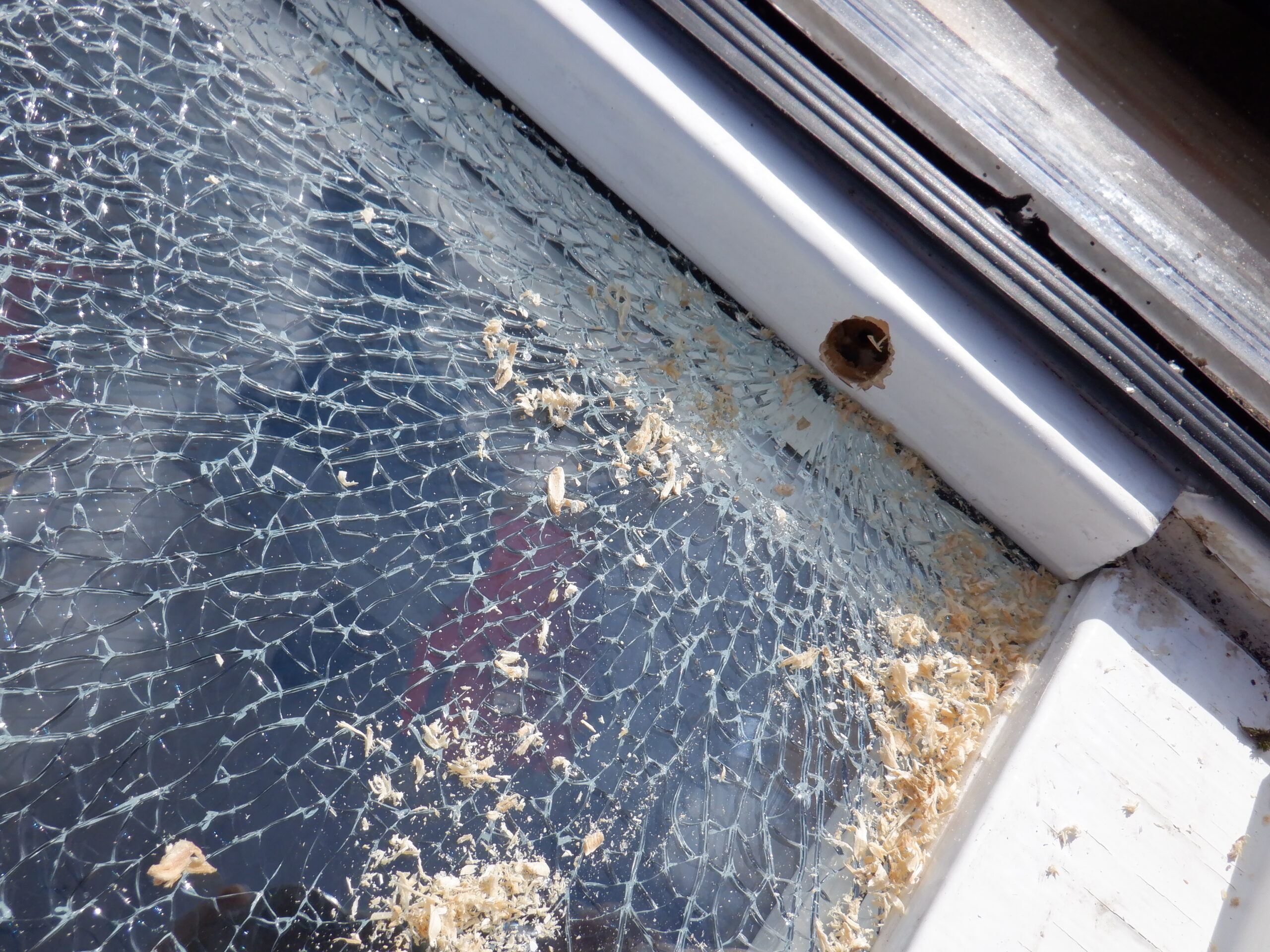
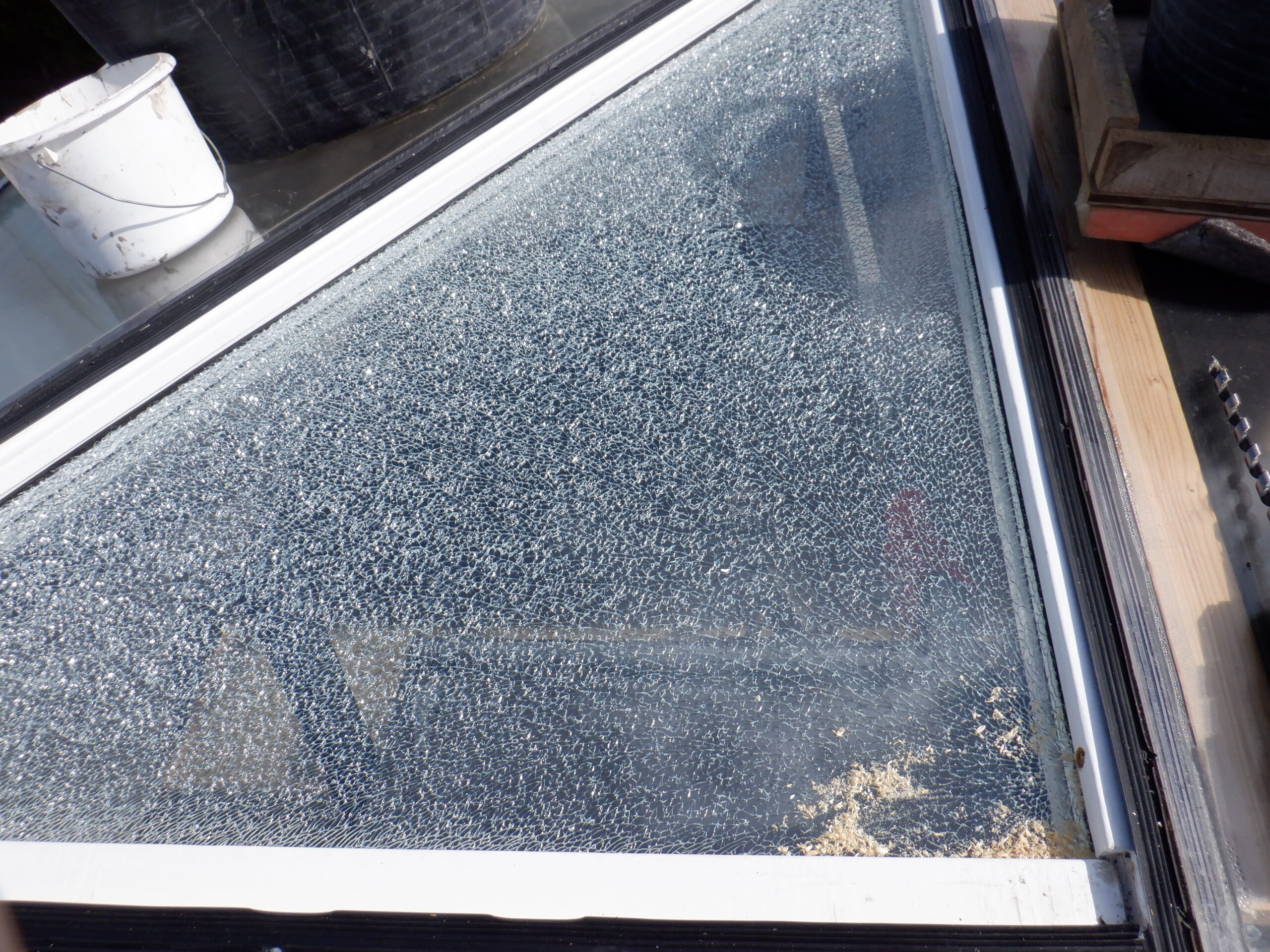
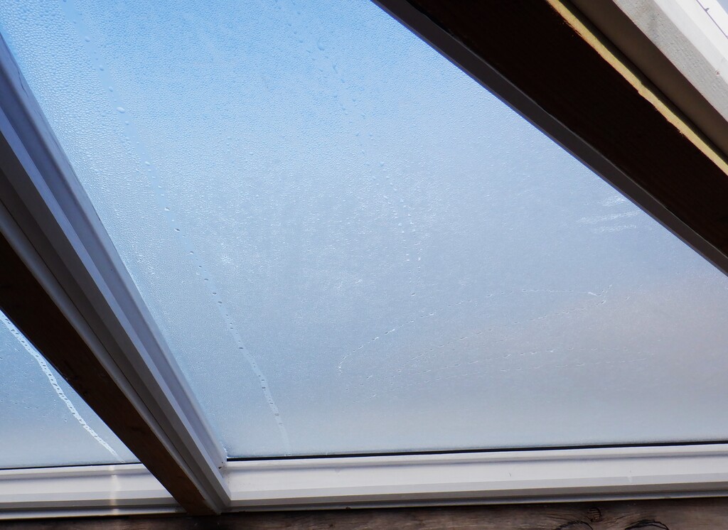
    This concludes most of the structural work for our Skylight for the time being. We now have to tackle the problem of the desiccant dribbling all over our plywood lining. Phew!

  • Solving Condensation Issues!

    Over the last three or four weeks, while dodging rain showers, we tackled the problem of moisture up inside our Skylight. See the following posts for more details:
    * Installation of Skylight Double Glazing Units – Part 2
    * First Stage of Improving Our Skylight Windows
    The solution to this annoying problem is to ventilate the gap between the double glazing glass units and the plastic polycarbonate outer layer. We decided that a neater solution is to drill air holes between each window section and then have one larger hole drilled in the middle position, through the central ridge beam, back into the boxing underneath the solar panels, where an additional fan can be installed, to force the air through all the windows in a loop and the “moist” air returns back into the boxing at each ends.

    It is quite a complicated task and we had to work from the roof side completely. We didn’t want to disturb the glass units because they were already fixed in with lots of sealant, but also they are damn heavy. Plus also, we cannot access the triangle windows over the Great Room. So, it was from the roof that we did all the work.

    It was slow work, as we needed to be safe while we got up onto the roof. Towards this safety, we assembled one of our old wooden platforms and positioned it around the back of the house, in the corner of one of our extensions. We then placed our giant extension ladder, using two of its triple segments. We taped on pieces of rubber foam to the top and bottom edges of the ladder, to cushion against the nails and bumps of the slate tiles. The foot of the ladder was fixed down to the wooden platform with a block of wood and rope. Then we had a smaller ladder to allow us to gain access to the platform.

    Setting up access for Skylight refurbishment

    Setting up access for Skylight refurbishment

    Next, the next step towards our safety regime, was to build three little foot rests that was connected to our steel wire we got running around the whole Skylight. we found some 11mm OSB left-over boards from when we were making the hot and cold water tanks, and screwed on a length of 2by4 timber along its length. This timber had a hole at each ends for a rope and a clip hook attached, ready to quickly hook to the steel wire. The other thing we did was to stick all over the underside of these foot rest with a thin layer of PU foam underlay we had lying around. This would provide some extra grip on the slate nails and also not to put too much pressure on the roof tiles as well.

    Now we are ready to get up on the roof.

    The first job was to undo the bird scarer. This is a set of three thin stainless steel wires stretched down the whole length of the ridge line of the Skylight. We rolled this up on a cardboard tube and then unbolted the brackets and lifted off the rain deflectors, which was in five segments. All these items were brought down to ground level and stored on our swimming lane cover for the short term.

    Then, we started on the first Skylight window, which is a triangular one and we undid the clamping bars that are holding down the plastic polycarbonate sheets. Once we got the cover off, we could remove the little aluminium tray of the desiccant crystals (which is now mostly a liquid). We put this into a large rubbish trug we had up with us (it had a couple of bricks in the bottom to hold it against the chance of winds). Then, we washed the desiccant chemicals away with a damp cloth and then tackled the job of drilling holes.
    We used a 16mm sized drill bit to make a good air holes.

    This first window is different to the other windows because it is a start (or an end) of the sequence of windows that we are planning to allow a flow of fresh air to blow around the skylight. So one side has horizontal holes to connect to the next window in sequence, but, the other edge needed diagonal holes drilled downwards so the air could escape back into the boxing that we will build to cover up the air ducting and solar panels etc. It was all guesswork so we probed by drilling a thin drill through and we can discover where the drill came out underneath. We wanted to miss the solar panel but also avoid coming out on the bottom edge of the joist. We had to be careful because the double glazing unit is sitting right there underneath where we are sitting! BUT, when we changed to the fatter drill bit, and proceeded to drill the larger holes, we must have very slightly clipped the edge of the glass and .. unfortunately .. scattered the whole pane of glass. It was toughened glass so it broke up into thousands of little pieces as it supposed to do. We had few choice words to say out loud !!!!

    Drilling a air vent and clipped the glass

    Drilling a air vent and clipped the glass

    Oops! We broke a window pane

    Oops! We broke a window pane


    We learnt a valuable, or rather, an expensive lesson! We scooped up all the broken glass into another smaller trug and disposed of that in the recycle bin.
    PHEW!

    So we adjusted our approach in drilling these diagonal holes and we were able to continue to produce five air holes.
    And then, we drilled horizontally on the other side, to connect this window to the next one. We did have to remove the polycarbonate sheet because the drilling angle meant that we could have scratched the plastic as the drill bit came out the other side.

    We then vacuumed up the wooden mess and and put back the cover, all the while in trying to minimise other dust and bits being blown in the wind. It was tricky. But, unfortunately, we discovered later on that our new air holes themselves actually allowed some of the wooden rubbish to be blown backwards into the previous window so we realised that we couldn’t rely on getting each window perfectly clear so we decided that we would have to perform a final vacuum on the return trip, once we got to the very end of doing all the windows, all twenty-two of them!!

    Drill holes to join up the window spaces

    Drill holes to join up the window spaces

    As you can imagine, it was a slow job in opening up one window at a time, removing the desiccant tray, cleaning, drilling holes, vacuuming the dust and then putting the cover back on. Including screwing the clamping bar back down with two screws (there were six or seven screw in total) and then moving on to the next window. We were using our foot rests so they needed to be moved along as well. Plus, on top of all that, we would get the occasional rain shower, which meant that we had to quickly cover things up and wait. Sometimes, we lost a whole day because of little rain showers coming and going. Phew!

    One different occurred for the middle set of windows, right over the staircase, because this is where we needed to provide a much larger single hole for the fresh “dry” air to get into this thin gap in the first place. We took the advantage of this situation over the staircase because there are two slightly narrower window modules so these became the beginning of the “circuit” for the fresh air to travel around all the air holes. So we drilled a large 25mm wide hole diagonally down through the central ridge beam, two of them, one for each of these windows. They popped out just below the solar panel as well, ready for tubing to be connected from a fan. More later.

    Holes through the ridge beam into skylight box

    Holes through the ridge beam into skylight box

    Re resumed doing the rest of the windows, going towards the Great Room and arrived at the final window before the start of the solar panels. Here we had to drill another set of diagonal air holes like last time .. but we were very careful and got five holes done without mishaps this time!!

    So after we had removed all the trugs of aluminium bars, dirty water and cloth and most of the tools, replacing them with the vacuum cleaner and one or two tools like screwdrivers, we started our return trip. We opened each window up in turn, vacuumed the last pieces of sawdust and put in plenty of glazing sealant on the joints of the rubber seals and then laid the cover back on and this time put all the screws back in the clamp bars. We put more sealant at the top of the clamp bars before putting the rain covers back on.

    We made steady progress, working our way back along the whole Skylight and in a few hours, got back to the beginning again.

    Nearly done

    Nearly done


    The final job was to remount the central ridge rain deflectors and then unwound the three thin wires back along the ridge and bolting the “arms” back into place to pull tight the wires.

    We have finished the external work of this task so we took everything back down again including the three foot platforms, a rain tarpaulin cover that we had tied a brick in each corner but we never got to use! We then carefully lowered the heavy ladder and put that away too. the final tidy up job was to disassemble the two platforms and return them to the storage stack in the swimming lane.

    Oh yes, one of the things we did while we had a platform assembled, was to do a repair job on the Front Porch roof. We had a slate split along an unseen fault line and half the slate had slithered out and a little way down the slope. The slate in question forms part of a line protecting the hip ridge line, on the right side of the porch. So we anchored the platform underneath the spot and proceeded to remove all the slates above the broken one, all the way to the top and levered them off their copper nails. We did end up breaking a couple more slates because the copper nails were ring shank types and really were stuck in the wood. We even broke the large central piece at the top as well! But, fortunately, we had a couple of spare large slates (measuring 300mm square). We then replaced all the slates again, including the new slates and nailed the final central slate back at the top.

    Repairing a broken slate on C roof Hip

    Repairing a broken slate on C roof Hip

    This the the broken one

    This the the broken one

    Slates removed to the top

    Slates removed to the top

    C roof All repaired

    C roof All repaired


    That concludes all the outside work but one of the consequences, is that we have scratched the polycarbonate plastic sheets up there and we will have to spend some future time to polish the scratches out, but when it is better weather and warmer!!

    We just needed to finish this particular job by installing a small fan we ordered off the web, connect it to a length of flexible aluminium “stretchable” 100mm pipe, which in turn got squashed down into two separate smaller flexible pipe that then plugs right up through the two big holes we drilled through the ridge beam. The fan is currently just plugged into the mains socket by hand when we can see that the Skylight needs blowing out, to evaporate the condensation accumulating up there. But, eventually, we will automate this process so that a timer will control when to run the fan and for how long. And possibly, detect the humidity levels up there and switch the fresh air supply on and off automatically

    Fan to ventilate the skylight glazing gap

    Fan to ventilate the skylight glazing gap

    This concludes this necessary work, in correcting a poor design choice we made at the start. We will have to live with this. But, it is now sorted!

  • First Stage of Improving Our Skylight Windows

    Today, on this lovely sunny Monday, we took the opportunity to go up on our roof, to our Skylight Windows, to do some upgrades and improve the windows. We have been having some problems with moisture getting in, but we never realised this had been happening because it is very, very small amount indeed. It is only because we have installed our double glazing units, with the moisture absorbing crystals, sucking up this small amount of rain water, and only in the last couple of weeks, some eight months later from when we installed the units, we are now getting leaks. They are coming from the metal tray of these crystals, which have now turned into liquid and running out of the trays. Yukkkk!
    Sklight first leak sign

    Sklight first leak sign


    So, we got the task of finding and sealing the windows better, hence this upgrade and improvement task.After careful analysis, even removing a section of the plywood on the inside of our Skylight, to dig around in the body, to backtrace the water, it seems to be coming from the glass and these trays. The “walls” of the Skylight are not damp at all, so the rainwater is not coming in from around the edges, underneath the glass.

    This leaves the rubber seals themselves that we got squashed on both sides of the polycarbonate plexiglass material. And when we inspected the window up on the roof the other week (very chilly and very windy), we noticed that the bottom edge is showing definite signs of water moisture underneath the plastic glass, inside the rubber strip. We can see quite clearly through the plastic. We then unscrewed the clamping aluminium bar that we used to hold down the bottom edge of the pane of glass, and it is very likely that the rain water is managing to slide pass the thin rubber padding we got under the aluminium bar, and dribbling into the screw holes we got through the plastic. We didn’t do a very good job of creating a seal to block off the clearance holes. Some of the holes had extra sealant in them, but no way enough substance. Not good at all. we decided that we will replace the thin rubber strip with a 18mm wide strip of butyl heavy duty black glue that is designed to be very long lasting and resistive to drying out and very very sticky. We did that aluminium bar on that day a couple of weeks ago and waited for better weather.

    That day came today when at last, we had a calm day and reasonably sunny as well so we got back up on the roof, to first unscrew all the aluminium bars off all the windows, a total of 32 of them, leaving behind the one we did earlier, and take them all down to our tools room. The one thing that we nearly forgot to do, was to label the individual bars with a location code so that we could return each aluminium bar back to its original place.
    We then used the bench sanding machine to clean off the old glue, throw away the thin rubber strips and then apply the new strip of the butyl black glue and get them ready to go back after lunch. They got a protective waxed paper on.

    Rooflight front strips with Butyl adhesive applied

    Rooflight front strips with Butyl adhesive applied

    After lunch, we took a bucket of hot soapy water and a scrubbing pad to clean the dirt away that was trapped under the bar and a towel to dry it off (it turned out that the Sun was strong enough to help dry the plastic by itself) and we went around clockwise with one of us cleaning the bottom edge of the window, moving backwards and the other poked the screws through the holes and the waxed paper, polished the surface to make sure that it is dust free and dry, position the bar down on the holes and tightened the screws up again.

    We completed the job at about 5pm and the last dozen windows was lovely because the built-in solar panels was hot from having the Sun shining on them so we had warm bums !!

    We couldn’t do many photos while we were up there and no one to take any of us sitting up on the pinnacle of our house !

  • Finishing the Skylight in Great Room – Part 2

    We resumed work on the Skylight on Monday after the Christmas break and we got on with filling all the little staple holes all over the fermacell boards with a gypsum-based filler which has extra additives to make it extra sticky and shrink proof. One of the things we thought that would make a better job of sticking this filler into these tiny holes, is to air blast them clean of any crushed fermacell material when the staple was fired in. This will provide a longer term finish.
    We also ran a bead along the joints and also the corners as well. We then ran all over the woodwork and filled in the tiny little nail holes in the beading that holds up the double glazing glass units, filling in knots holes and the various joints along the ridge beam and metal work.
    All these fillings were sanded down and where discovered, refilled any holes that did actually shrink after all. This is a bit strange since the filler boast that it doesn’t shrink so we concluded that the water is being struck out into the dryer fermacell material (which is gypsum and newspaper mix) before the gypsum has the chance to form the lattice work during the curing process. Another job we did was to trim the bottom edge of the vertical sections of the walls and then rounded it gently to soften the edges plus also to protect against being bashed and having little chunks fly off.
    Starting to decorate skylight

    Starting to decorate skylight


    The next job is to paint the wood framework with universal combined primer and undercoat white paint, and a metal white paint for the steel cross tie. We had a little issue with one of the Skylight rafters where a knot hole kept on “leaking” colour when it got painted so we got out our oil-based primer and dabbed that area which did the trick. We repeated the undercoat for the second time all over to make sure that everything has a good strong whiteness.
    We, while waiting for the woodwork to dry between coats, applied a coats of white emulsion on the walls, using a regular bulk white emulsion and then finishing off with a high quality brilliant white paint.
    GR Skylight Decorated! (1)

    GR Skylight Decorated! (1)

    GR Skylight Decorated! (2)

    GR Skylight Decorated! (2)


    At this point, everything that we needed our mobile working platform to reach high up is finished so we moved it away to the other end of the first floor, ready for some future task like building the boxing that will hide the backs of the solar panels and the air ducting etc.
    We can now finish constructing the rest of the gable wall going across the Gallery, putting in the doorway etc and shelving units, blocking off the gap between the two steel posts holding up the Skylight.
  • Finishing the Skylight in Great Room – Part 1

    One of the areas that need to fully completed, including painting the woodwork, steel cross ties and the walls with paint, is our Skylight in our Great Room. Because this section of the Skylight stretches over beyond the Gallery, we had to extend the Gallery temporarily so our mobile working platform was able to be employed so we didn’t have to keep climbing up and down ladders. It was far safer and much quicker to do the various tasks.
    Work platform on Gallery

    Work platform on Gallery


    One of those tasks, was to build a blanking off wall, to extend our Gable wall, all the way up to the Skylight window frames themselves. Our interior Gable wall is aligned to the edge of the First Floor and it is thick enough to hide our large 6inch steel legs that are supporting the Skylight and we have designed the alignment to coincide with the Skylight Windows themselves, and it turned out to be very close to what we wanted. We had to lean backwards, very slightly, our vertical piece of wall, to meet the wooden framework of the window. We could have gone up perfectly vertically but we would have had a small 40mm “shelf”, collecting dust and dirt, hence we went for the gentle slope instead, which also will help reflect more light down to the Gallery and the Great Room.
    Skylight walls (2)

    Skylight walls (2)


    We then turned onto the two sides of the Skylight vertical walls and proceeded to give them a good hard sand, to get rid of years of weathering and make them ready for gluing and stapling up more of our fermacell boards. We had to do these sections in two halves because we got a steel cross tie that is half way up inside the Skylight, which is there to support the ridge beam and rafters of the windows themselves.
    Now, we tackled the last side of the Skylight, the one that comes down to align with our mobile lighting module. We wanted it to come down to our aluminium lighting channel that we got running around on all sides of the lighting module so we had to extend this fourth side further by another 150mm, making a total of 900mm. We also had to add an 18mm spacer, to bring out the surface, to align it with our aluminium channel. This meant that we had two “wings” to build as well, going underneath the edges of the Skylight and meeting up with the slopes of the ceiling. It was quite tricky to get everything measured and cut to the correct shape and size, but we managed it.
    Skylight walls (3)

    Skylight walls (3)

    Skylight walls (1)

    Skylight walls (1)


    The next task was to put a narrow strip of fermacell just above the doorway in our gable wall, going from left to right so that we could then install a flat piece of “ceiling” board under the Skylight two edges, coming perpendicular out from the Gable wall. These will have further lighting units installed, to help luminate the Gallery etc.
    Skylight wings (1)

    Skylight wings (1)

    Skylight wings (2)

    Skylight wings (2)


    One job was to put on a “pretty” cover on the ridge that is holding the windows and we used a piece of oak plank we had left over from doing the guttering. We trimmed it down to a 80mm wide piece and then created a “jigsaw” like joint, to go around the metal post. We chamfered a small 45degree bezel around the three edges and then screwed and glued it up.

    We then, modified our belt sander machine, to provide a method of sanding the finished fermacell surfaces, especially all the edges and joints. We used the existing frame that came with the machine and we added two 3mm thick aluminium bars to sit top and below the sander. The sander is then adjusted so that it is just skimming the surface when the machine is flat on the surface, without digging in at all.

    Surface sanding system (1)

    Surface sanding system (1)


    We put on a very rough sanding belt so it didn’t take too long to tackle the job of removing the steps in the joints, which indeed it didn’t! We went around everywhere in the skylight area quite quickly which is good because we will have to tackle the rest of the sloping ceiling surfaces everywhere.
    Surface sanding system (2)

    Surface sanding system (2)

    Surface sanding system (3)

    Surface sanding system (3)

    Wall after sanding

    Wall after sanding


    That concludes this first part of getting the skylight finished. We will have a Christmas break now and return in the new year for part two.
    Merry Christmas !!

  • Skylight Double Glazing Units – Part 2

    These last two weeks saw the installation of all our double-glazing units up into our long Skylight at long last.
    But one of the last pieces of preparation work to complete was to cut the freshly painted white battens into twenty-two sets. Fourteen of them had four pieces and eight had just three. We took the glass size of each unit and added a generous 20mm to their measured lengths and cut the battens accordingly.At this point, we had to inform our glazing supplier that two of the triangle units were not manufactured correctly. We had specified that these two particular windows had a very slightly non-right angle corners and we had clearly indicated this in our drawings we had sent off, but somewhere along the process, this piece of information was lost and it was only third time lucky, after we had to strongly argue with our supplier that there are such things as non-right angled triangles, we finally received the correct shaped units yesterday. They fitted ok .. more later !

    So, in the meantime, we started at one end of the Skylight, at the North end and specifically number 18, the first square one and proceeded to install each one in turn. Our first one nearly took all day to do as we were learning the procedures and order of getting each step done correctly. The first step was to test fit the glazing unit up into that window, to make sure the physical glass went in and had enough gaps all round for the sealant to go in. Then, it gets taken over to the cleaning department so that the outward facing surface was thoroughly cleaned and polished. There is only one chance to get this done perfectly because we won’t have access afterwards. At the same time, the polycarbonate outer glazing pane was also polished and double checked for any ‘dirt’. The double sided sticky tape was stuck all the way around the framework. The third step in our procedure is to put the glass unit back up into the Skylight and hold it up using two temporary wooden rectangular battens with two screws in each, to take the stain of holding the weight up. These 28mm thick units, comprising of two panes of 4mm thick toughened glass and 20mm space that has been filled in with argon gas, were quite heavy, ranging from 17kg to 26kg for the square shaped ones, and about 13kg for each of the triangle ones. This made them just a bit too heavy for a person to hold it up while we did various tasks, hence the two support battens on each of the upright sides.

    Uint held up by temporary battens

    Uint held up by temporary battens


    At this point, we balanced the position of the glass unit by putting in plastic spacers on each edge, so we had an even gap all the way around. We wanted a sufficient gap to squirt in our low modulus double-glazing approved white sealant and make sure that it is completely sealed against any water vapour and dirt from entering the upper chamber. So, we stuck down bent over plastic spaces around the edges so when we insert the glass unit in for the final time, it will go up straight and evenly in one go, without worrying about accidentally slipping sideways and sticking the glass in the wrong place.

    Putting spacers in to center the unit

    Putting spacers in to center the unit

    At this point, we can release the glazing unit and lean it ready to one side of our working platform.
    we now need to make up the two trays that holds the desiccant powder, cover it up with a breathable cloth tape and put two pieces of aluminium sticky tape at each end to seal the cloth tape to the tray, to stop the powder coming out.

    Dessicant tray with tape on end

    Dessicant tray with tape on end

    Dessicant tray filled with chemical

    Dessicant tray filled with chemical

    Dessicant tray covered up

    Dessicant tray covered up


    This powder is highly active in absorbing the water moisture out of the air and we had to be very careful to tidy up afterwards each time we make a tray, or we get a horrible pool of very wet ‘sludge’ as we discovered! We modified our procedure, and we collected up any spillage by using a strip of toilet roll paper and poured any excess back into our pot of powder, clean the worktable, and vacuumed it as well to remove any fine powder.
    These two trays then were immediately put up into the Skylight, to sit on their little prepared shelves, one at the top and the second one at the bottom. Then, the security tape had its protective wax paper peeled off and we lifted the glazing unit back into place, making sure that our plastic spacers were all still in place and push up hard to stick the glass to the sticky security tape. We reapplied the temporary battens to hold it in place as we don?t trust the security tape to hold the glass forever!

    The next part of our long list of tasks to perform, is to measure the bottom and top edges and cut the battens with 45degree angles at both ends, using our chop saw. We had our super sharp mitre guillotine up on our platform, to allow us to trim a tiny bit off the length until the battens fitted in. A thin double sided security tape was then stuck on these wooden battens. Meanwhile, we used our compressed air sealant gun, to push a decent amount of sealant into the gap between the glass unit and the frame, all the way around on all edges, except the small section blocked by the temporary holding battens. We generally use about one and a half 300ml tubes of sealant for each window, but sometimes it is a bit more and sometime a bit less, depending on how big the gap around the glass unit is. We had bought thirty-six tubes and, we very slightly under-estimated the quantity, so we had to order two extra tubes!
    Anyway. The next step is to push the batten hard up against the glass (remembering to peel off the wax protective tape!) and then nail the wooden batten into place using 50mm long brad nails, using another one of our compressed air nail guns. These nails have very tiny heads, so we only need to put very small spots of plaster filler on and rub it smooth, ready for painting. All this will be done later.
    Having, done the bottom and top battens, all nailed and secured, we then can unscrew our temporary battens of the vertical sides and then finish squirting in more sealant to complete the full circuit. Here, we then measured the final two battens for the vertical sides and fitted them into place, with any small trimming to ensure that the mitre joint is neat as possible.

    Nailing the battens in place

    Nailing the battens in place


    That finally, concludes the procedure of fitting one of these windows! As you can see, the first one took us many hours to get it all done, but after the fourteenth one, we were getting them installed in about 75minutes!

    Then, we tackled the triangle ones! At this point, we were now in the Great Room so three of the four windows went in smoothly. The only addition that we had to adjust in our procedures, was that we needed to be able to cut a mitre angle at 22.5degrees, half of a 45degrees which are the normal square corners. Now, the four triangular windows have one 90degree corner but two 45degree ones which means that we need a way to cut the battens with an even sharper angle than the machine can manage. We made a ‘wedge’ to support our batten with an additional 22.5 degrees rotation and the blade now can slice long diagonal cuts.
    So, as I was saying, three of them went in with reasonable ease, following all the steps we did before, but, for the fourth one, we discovered that the glass unit wouldn’t slide into place. It is very similar to the first window we put in a couple of weeks ago and like that time, we had to file and grind the framework on the long hypotenuse, to widen the ‘entrance’ to allow the glass unit to slip in. Once inside, there was enough gap all round so we resume our list of tasks and got that window done as well.

    Lot's Double glaing units (1)

    Lot’s Double glaing units (1)

    Lot's Double glaing units (2)

    Lot’s Double glaing units (2)


    The final stage of doing the Skylight windows was back down at the other end, to put up the last four triangular units. Two went in ok as usual, and then we had the delivery of the two special ones with their non-standard right angles and we got them in too. One was very tight and the other one was very loose! It used up a lot of sealant and we were very glad to have ordered those extra tubes!
    One observation we made today was the huge amount of condensation there was on these two last windows. The temperature had dropped overnight to below 10°C and the air inside our house was 60% humid and contained lots of water because it is still warm inside and we arrived this morning to find the outer polycarbonate pane covered in loads of water.

    Condensation on a plain window

    Condensation on a plain window

    We wiped it all off. We then went to inspect all our other twenty windows that we had completed before today and there is no signs of any condensation at all. This is very hopeful and we keep our fingers crossed for these windows surviving for the long term. It depends on how good the outer rubber seals are on both sides of the polycarbonate pane. We can gain access from above if we need to do any extra sealing in the future and replace the desiccant material with fresh dry stuff.

  • Skylight Double Glazing Units – Part 1

    We started the new week by tackling the task of installing our new double glazed units up in our Skylight. We have twenty-two units to put up, 8 triangles and 14 rectangles.
    But, the first job is to prepare the framework and make sure that it is nice and solid, without any gaps etc.
    So, using our new High Platform, we went along and blasted out all the crevices with compressed air, put in short lengths of 10mm PU “sausage”, squashed into the gaps, to help to reduce the amount of sealant, squirted in plenty of sealant and bringing it all up so everything is more or less smooth and level.

    Next, we gave the windows a thorough clean on both the outside and inside. Shaun went outside on top of the roof with a bucket of hot soapy water and armed with a squeegee and sat on the Skylight itself. He lent over to reach all corner of each window with the microfibre scrubber pad and then drew off the water using the rubber scraper. The windows haven’t been cleaned for several years so it took a while to get the dirt washed off. Shaun shuffled clockwise around all twenty-two windows and ran out of energy, and clean soapy water, by the time when he reached the solar panels so we will come back another day to do those.

    Shaun washing skylight windows

    Shaun washing skylight windows


    We will invest in a long handle cleaning tool that can telescopically extend out but also has a hose pipe going up the middle to supply a flow of water at the same time while scrubbing the surface. This tool will also serve to clean our seventeen solar panels as well. It will save us having to clamber up onto the roof tiles and be able to do this task from the ground itself, or at least, on a high platform at the gutter level.While this was happening, Stephen went around inside to clean the inside surfaces of the windows, using a little gadget that scrubs and sucks up the dirty water at the same time. But, it was also needing several washing cycles and each were polished with a microfibre cloth. He was standing on our high wooden platform. These windows needed to be extra clean because they won’t get a second chance after the double glazing units gets sealed in later in a few days.

    We were considering what sort of battens to secure and fix up the glass units, and after thinking about making it out of Oak, we decided to phone our local timber merchant and ordered a set of planed 21mm square beading. They come in 4.2metres lengths and we calculated that we would need 23.5 pieces so we round this up to 25 lengths just in case. It is quite shocking to how high the price of timber is these days, it cost us about £1 per metre of 21mm by 21mm planed pine wood and only a couple of years ago, we paid £1 per metre for 63mm by 38mm planed timber!!

    Next we adapted a compressed air sealant dispenser tool so that we can get a constant pressure and flow of the low-modulus neutral cure glazing sealant that we need to squirt all around the edge of the 28mm thick glass unit and make sure that it is completely filled in. The problem we got with our existing tool, is that it is too long. It was designed to take a higher capacity sealant tubes that were 1½ inches longer. It is a pity that there wasn’t a unscrewable section on the body of the chamber and therefore adjust the tool to take shorter sealant tubes.
    We made an internal extender to take up the slack by cutting out three circles from a piece of 12mm thick cement board, measuring 47mm diameter, using a core cutter. These three pieces were glued and bolted together to squash the joints and waited overnight for the glue to set. Next we found a little length of 50mm wide plastic pipe which is a fraction too wide to fit inside so we sliced a very small chunk out of it so it can close up to fit smoothly into the gun. Then, we “turned” the solid cement plug very fractionally so it also just fitted smoothly inside the plastic sleeve. We made sure that the cement core was exposed by 5mm or so so that we can slide on a fat O-ring rubber seal over the cement core and sit snuggly down to the edge of the plastic sleeve. The whole lot (minus the rubber O-ring) was glued all together so that it forms an air tight plug with just a small hole down the middle to allow the compressed air to enter the tube of sealant. The O-ring squashes up tight to the ends of the sealant tubes and the cement plug also seals against the original rubber seal at the bottom of the gun.

    Air powered Sealant gun

    Air powered Sealant gun


    It works very nicely without any air leaks! We can now go ahead to provide a steady flow of sealant for our glass units when we get them installed up into the Skylight.

    We also modified some sealant nozzle to flatten them to allow the sealant to be pumped into narrow gaps around the units.

    Modified sealant nozzle

    Modified sealant nozzle

    Our wooden battens arrived this morning (Wednesday) and we got on with shaping all 25 pieces in our router machine attached to our router table. We just wanted to put on a single extra flat surface on the corner of the square 21mm by 21mm batten, to chamfer at a 45degree angle a third flat surface to provide a slightly more pretty finish than just plain square.

    Double glazing battens

    Double glazing battens


    We then proceeded to give all pieces two coats of primer and undercoat, rubbing them between coats and get them ready for when we install the glass units.

    The last piece of work for this week is to make the moisture extraction system. It sounds fancy but all it is, is a tray of desiccant powder with a breathable tape over the top. We bought a heap of long 1inch wide by ½inch high extruded aluminium trays, measuring 5metres long. We then cut these up to make two trays, one at the top and another one at the bottom, in each square window and one tray at the bottom of the triangle windows. We had pre-built a little “shelf” in each window, to hold these trays of desiccant but, we discovered that some of them are slightly tight so we sliced off a couple of millimetres to reduce the height of these trays. We made 36 trays in all, with eleven of them reduced in height. We also rounded the ends and then taped a small piece of aluminium tape to seal off the open ends, to retain the crystals.
    Lastly, we test fitted a couple of our triangle glazing units because we discovered that the last two units that we had to order again were not correct. We were cleaning off some sticky tape that the glass people had put on and cutting off excess amount of the tough sealant that is filled inside in between the panes of glass, when we tested the angle of the “right angle” corner and discovered that wasn’t correct. We then measured all three sides and the glass people neglected to take any notice of the hypotenuse and just assumed that these two triangles were exactly right angles when they were not. For some reason, they failed to noticed that these two triangles had special angles. We took them up to the Skylight and made sure that we couldn’t get them in. We will now have to go and chase them up and get them to admit their mistake. What a Fuss! We tested two more triangle windows, number 22 and number 19. Number 22 fitted in straight away but number 19 was ever so slightly too tight and we had to make some minor adjustments to the wooden framework so we could eventually get the glazing unit to fit into place.
    Finally, just for completeness, we also tested one of the square windows, number 18, and it went straight in with no fuss at all.

    We will carry on in dealing with the Skylight windows so it is all done, before we resume working on the Great Room.

  • Decommissioned the Slicing Table and Converted it into a High Working Platform

    Today, after we have sliced up all the remaining foam boards yesterday, we proceeded to demission the slicing table, taking off the sabre saw that had been mounted underneath the table (with the blade sticking up through the top) for the last couple of years. We converted this table and extended it original 8foot by 4foot size by adding another 2feet width to the long side, reinforcing the framework, extending and putting in additional legs and then stiffened the whole thing up with bracing structs so that the new working platform is much stronger, safer and also much higher so we can reach comfortably the Skylight.
    Skylight work platform,

    Skylight work platform,


    It has a tactile edge strip all the way around the edge of the 8feet by 6feet platform so our feet can detect when we are getting close to the drop off, especially that the platform is five feet off the ground now! We will need a step ladder to climb on and off it!!
    We are using this platform so that we can easily install our double glazing window units, but also, we can build the upper boxing on the back half of the Skylight for the air ventilation, solar panels, the window blinds and lighting units, all inside this box-shaped construction.
  • Sliced Off Dangling Metal Posts

    The first use of our new High Platform, that we built earlier in the day, was to go along up in the Skylight and slice off the small metal posts that are hanging downwards from the steel cross members in the skylight. These posts were originally intended to allow a wooden framework to be constructed, to box in half the Skylight and extend the flat ceiling portion of the room.
    But, we decided that would feel too “crowded” and we liked the idea of opening it up and make it more airy and also allow more of the Skylight sunshine to pour in and reach the back half of the rooms.
    So, we used our 5foot high platform and a pair of angle grinders tools with one having a cutting disc and the other having a sanding disc. We proceeded to slice off all eight stubby posts.
    Removing Downward stubs on Cross beams

    Removing Downward stubs on Cross beams

    Stubs cut off

    Stubs cut off

    Stub free cross bars

    Stub free cross bars


    We will weld on some new metal tabs in the future and allow us to screw up a set of sheet material to form the box that will house the ventilation ducting and other bits and pieces living up there.