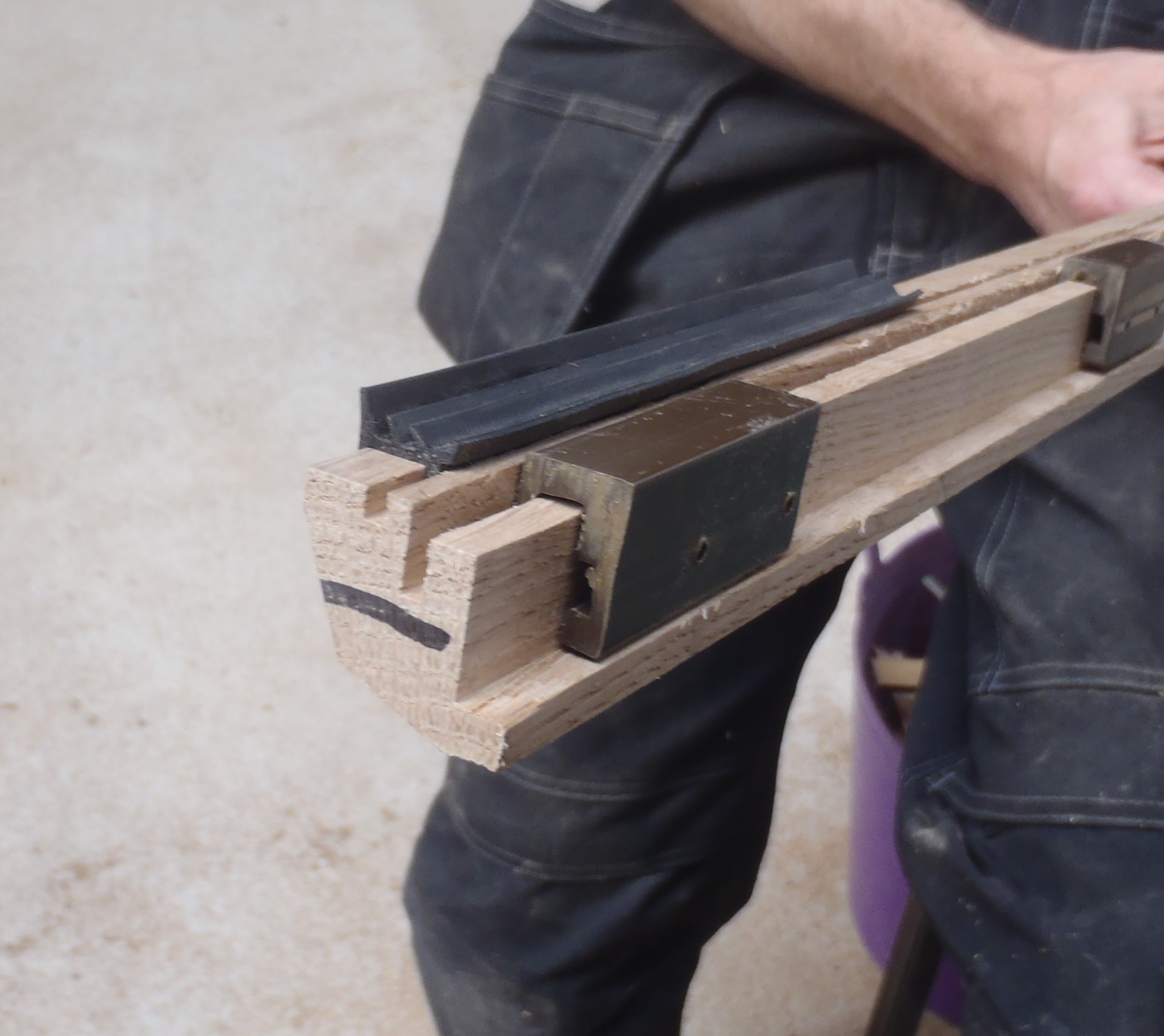
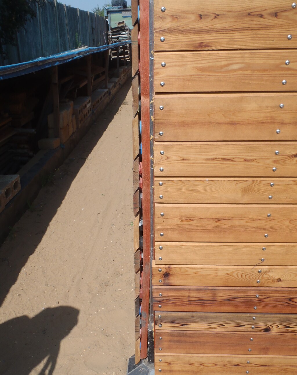
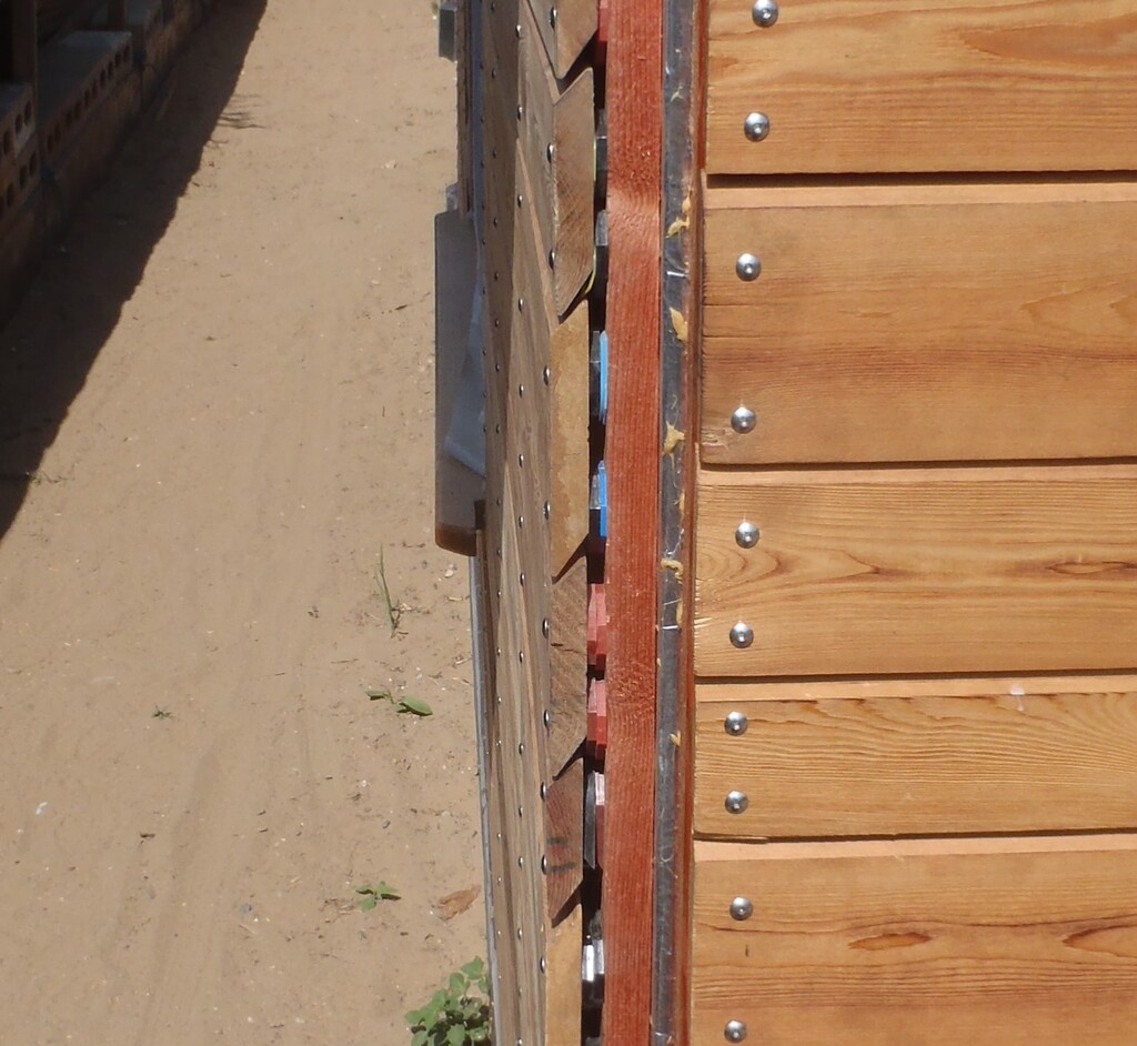
We resumed work after our so-called holiday on two separate streams of work, one to develop the automation infrastructure and Development Environment (see Creating The Automation Development Environment) and this stream where Stephen needed to manufacture specialised plastic pads to support the glazing units. Our units are triple glazing with 6mm thick glass separated by two 16mm wide gaps filled in with Argon gas. Hence, the total thickness of our glazing units are 50mm. We couldn’t find these to buy on the web and we had a special requirement because our window sills have a unique shape. We wanted the slope to go under the glass a small distance to ensure that any rain water will be encouraged to run out again if any got in or leaked pass the glazing beading strips.
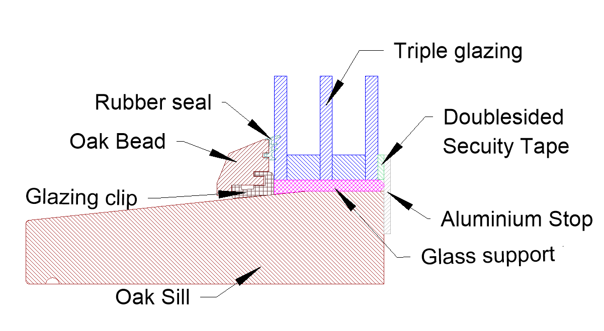
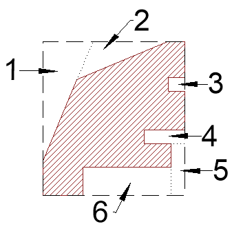
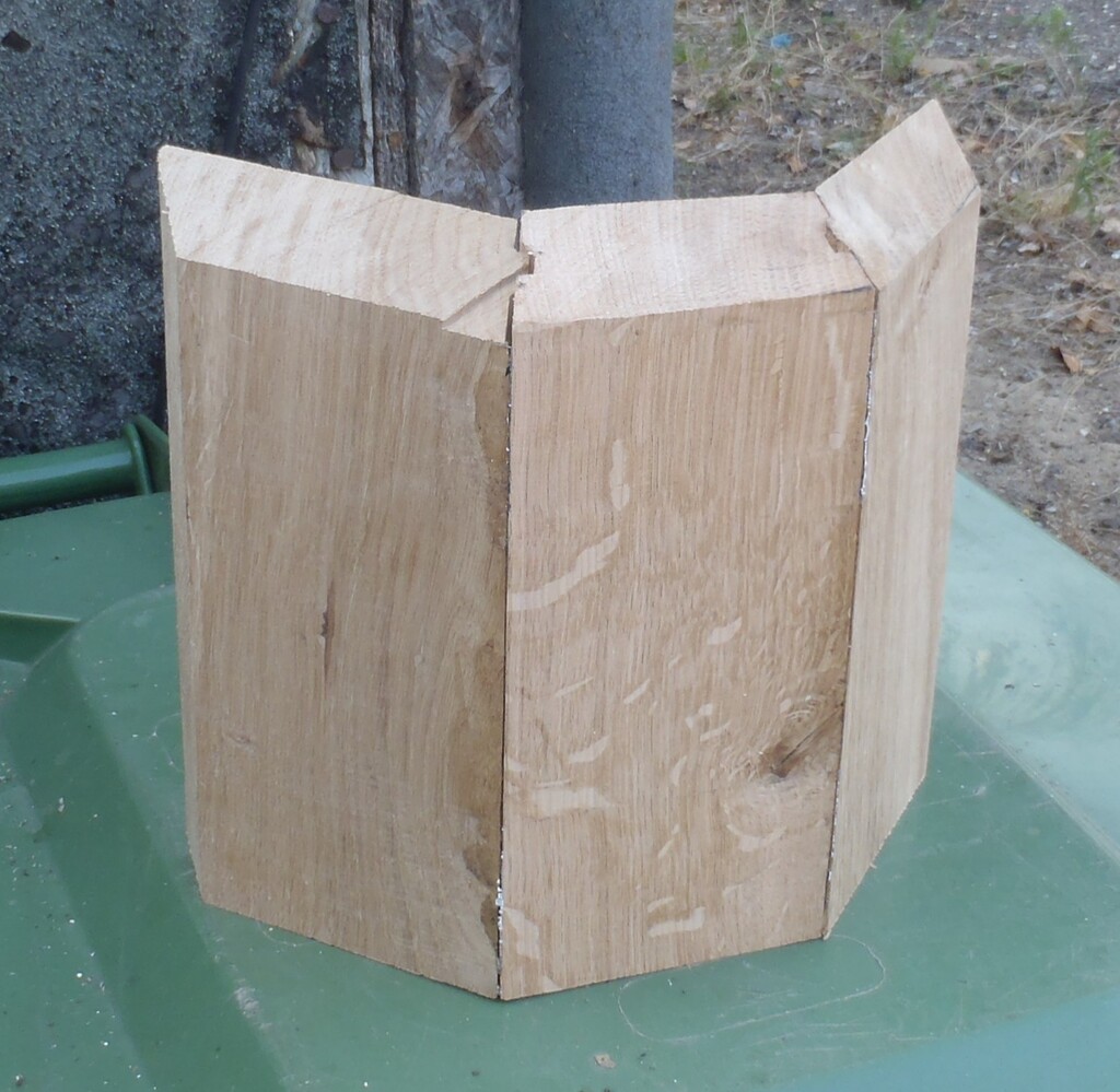
Window bottom cross section
There is a flat area of 35mm wide and then the slope starts which goes all the way to the front of the sill, this means that our plastic pads had to grow thicker to accommodate the slope (The Pink bit in the above picture).
Here enters our 3D printer!!
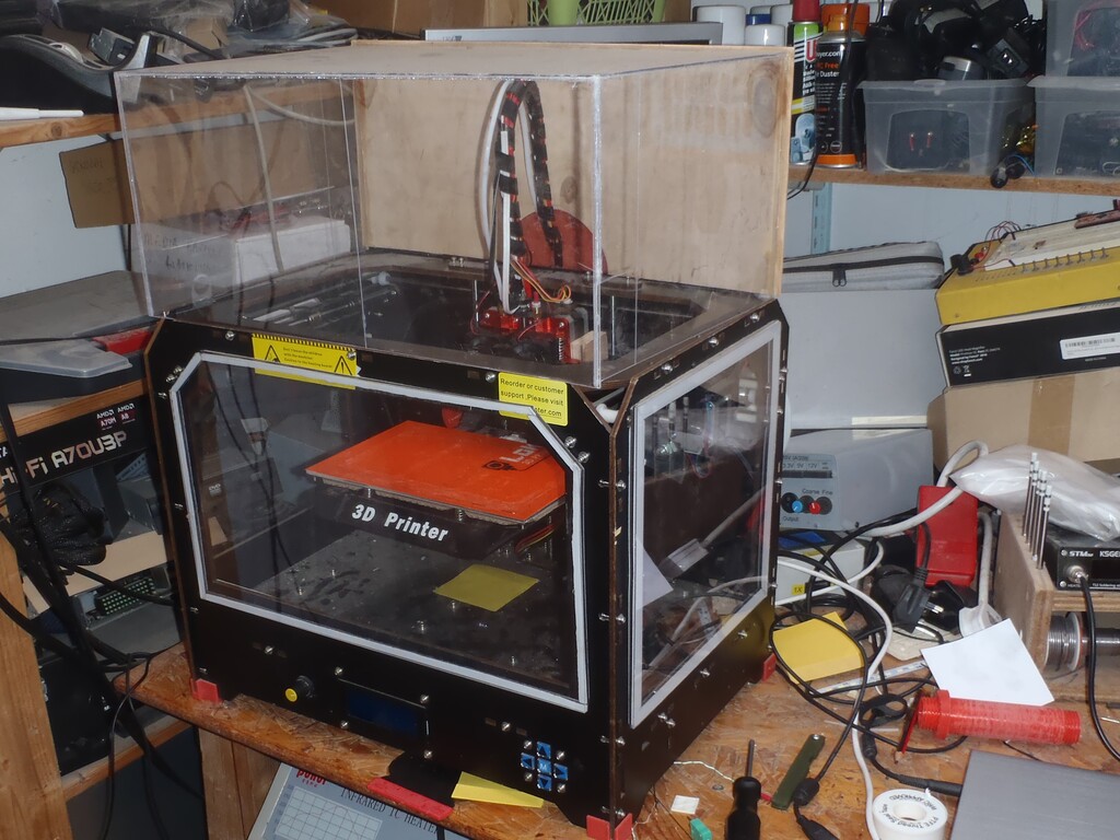
The-3D-Printer
We had our 3D printer for a few years now but it is the first time we are using ABS type of plastic, ABS being a much tougher material and also offers a very long lifetime resilience, especially for the outdoor environment of rain, sunshine, insects and dust!
Stephen started to do some printing with ABS but it was not very successful, the plastic was not flowing well out of the nozzle and as the printer has to work at higher temperatures to melt this type of plastic, Stephen decided that certain parts of the printer needed upgrading.
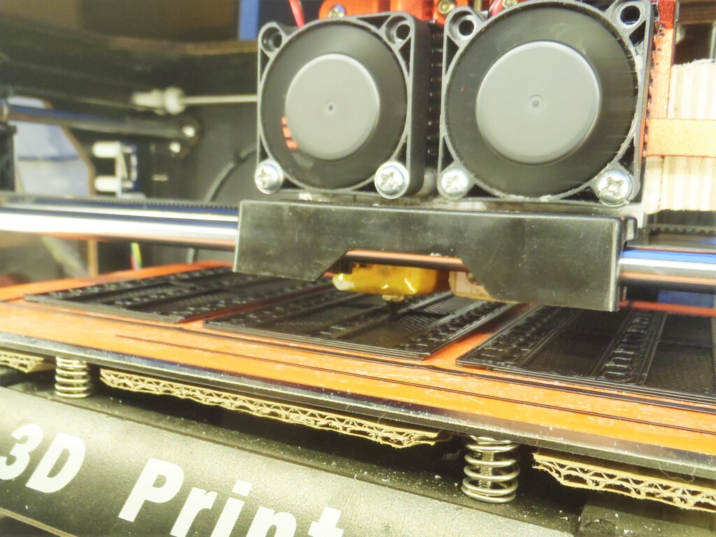
The first thing to improve is the heat retention of the base plate that all the plastic objects are created upon. It is normally heated but we found that it wasn’t getting the temperature high enough to keep the ABS plastic steadily hot so that it does not warp by cooling too quickly. The improve this we glued the heater to the base plate (it was just placed against it before) and a piece of double corrugated cardboard was placed on the underside to insulate and retain the heat longer. It works very nicely now!
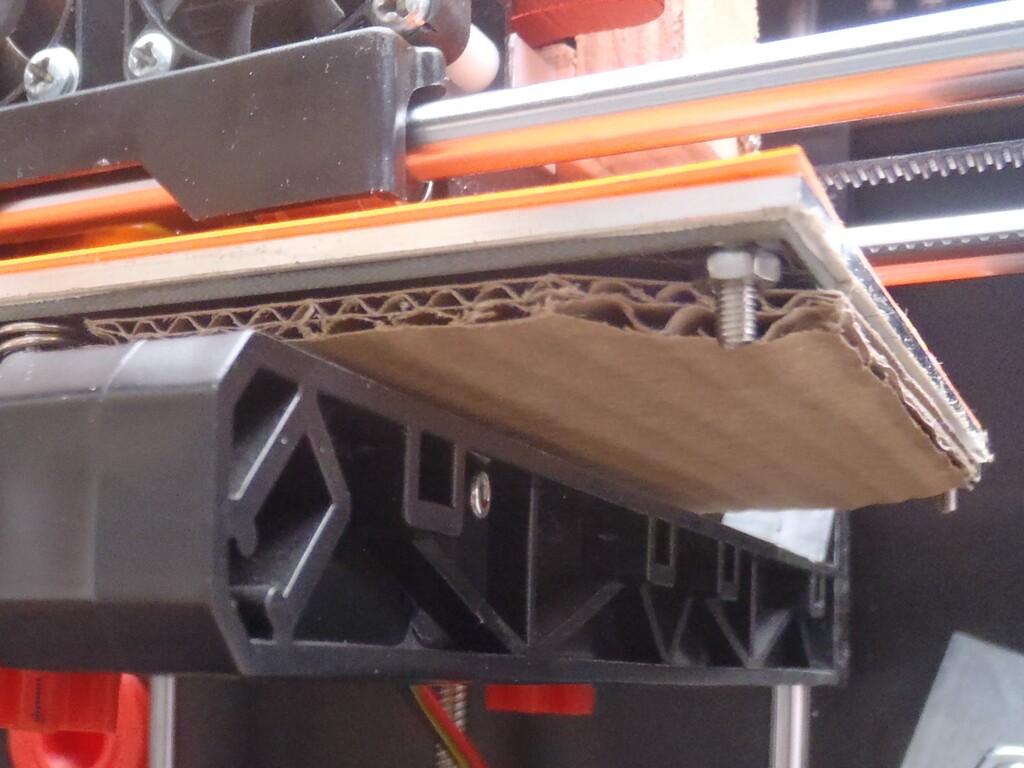
Improved-build-plate
The second upgrade was to the roll holders at the back of the machine, where the plastic filament rolls are stored. The large rolls are quite heavy and the weight was causing higher friction which gave problems to the feeder motor that was trying to pull the filament into the melting chamber. The solution was to make a conical plastic holder with a ball race bearing fitted in it. We printed two new pieces, using our 3D printer of course, fitted the bearing and threaded both on a rod with wing nuts.
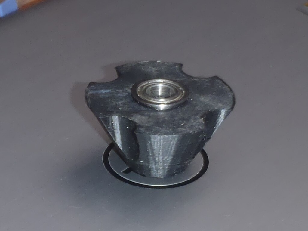
New-spool-support-cone-with-bearing
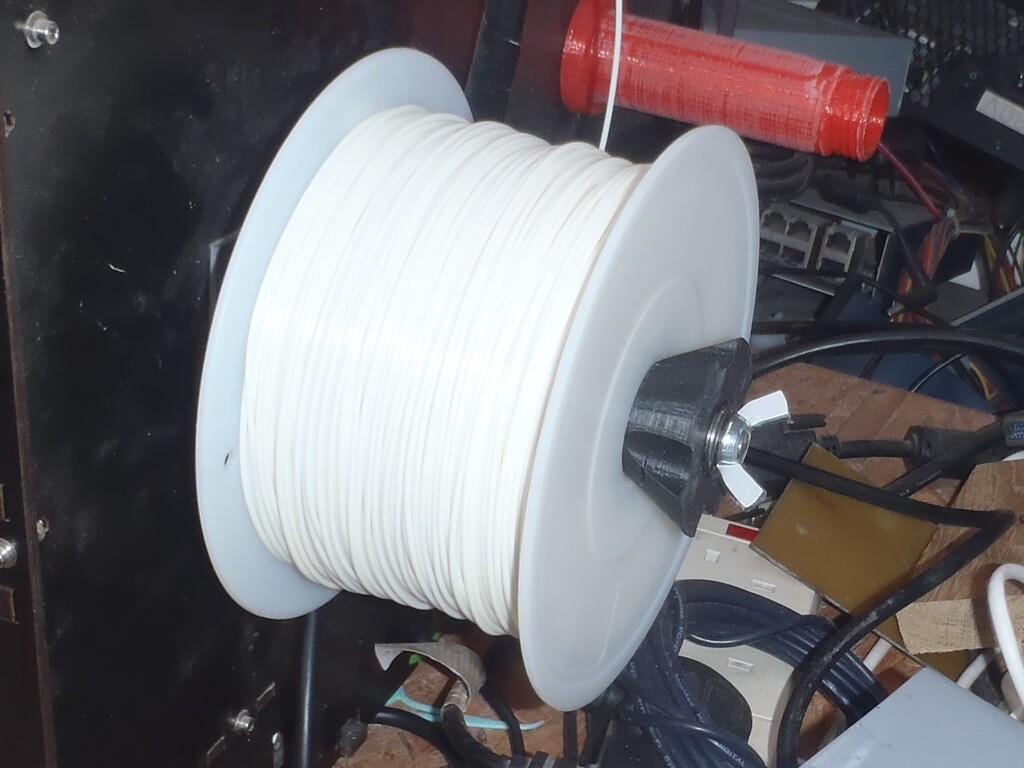
New-filament-spool-holder
In the meantime, we had ordered a replacement all-metal spring loaded mechanism to improve the grip strength of the feeding motor, the old one being plastic and unsprung and we felt that the quality of feeding the filament into the nozzle was important to maintain a good pressure and flow of melted plastic.
The new extruder needed a lot of fiddling, filing, buying longer bolts etc. to get it to work well.
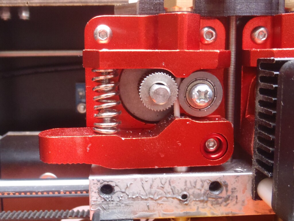
New-Extruder-motor-unit
The final part of puzzle was realising that the temperature of the extruder nozzle was not as hot as the machine was saying it was (It should have been 230°C and was actually below 200°C). I added extra insulation around the heater but it did not help so I just told the machine to heat it to 270°C to get an actual 230°C temperature.
Now we could start printing in earnest and we successfully printed a support, but we had parts where we still weren’t getting proper extrusion, so I slowed the printing speed down and got much better results. But each pad was taking 55 minutes to print. This was mainly because we were printing layers only 0.2mm high (50 layers for the print), I increased the layer height but found I couldn’t extrude fast enough with the fine 0.4mm nozzle so I bought a 0.8mm nozzle. This allowed a print time of just 20 minutes with 0.5mm layers, so I could print 3 supports at the same time in about 1 hour.
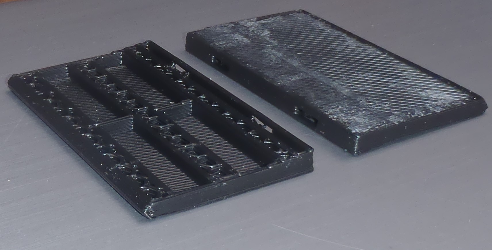
The-final-printed-supports
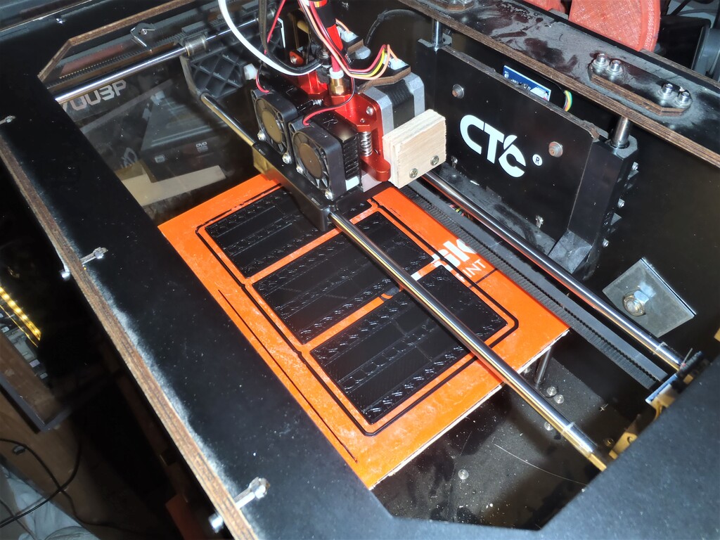
Printing-spacers-1
Printing-spacers-2
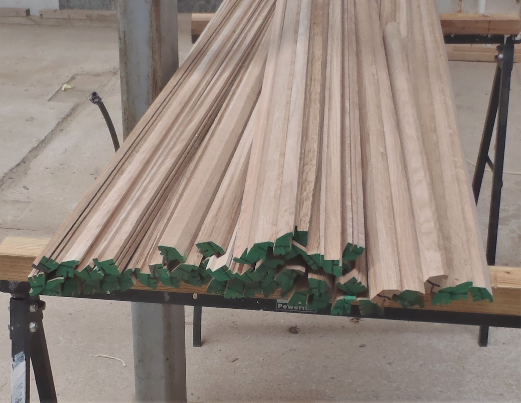
We only print supports under the actual glass panes and leave hollow elsewhere. So after 2 weeks of fiddling and upgrading we had all the supports made (with a few spares).
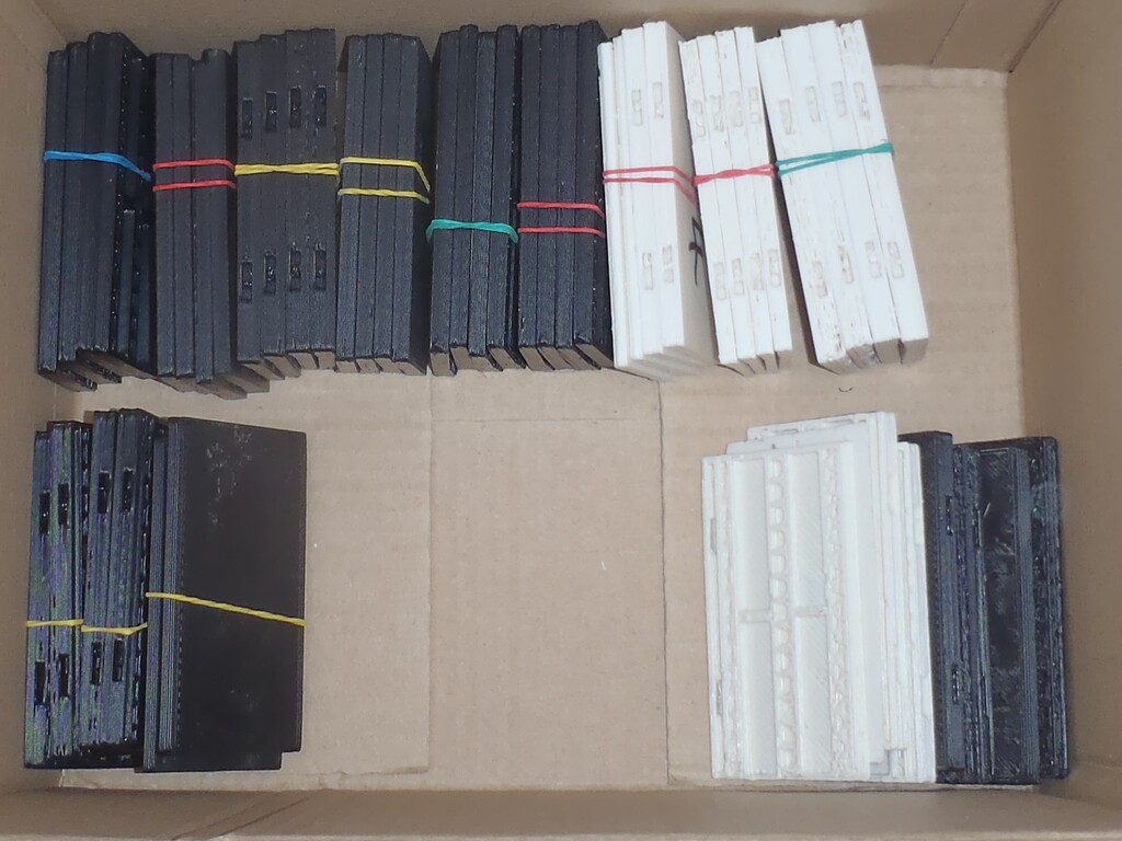
All-the-supports-printed