Category: Walls

  • Larch Cladding Timber Oiled and Burnt in Various Ways!

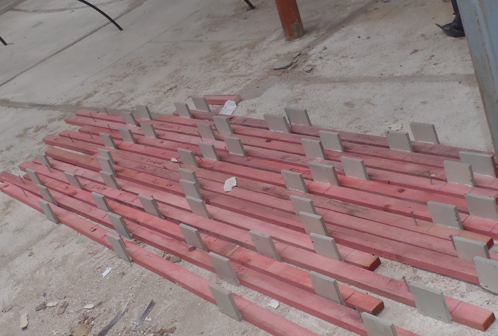
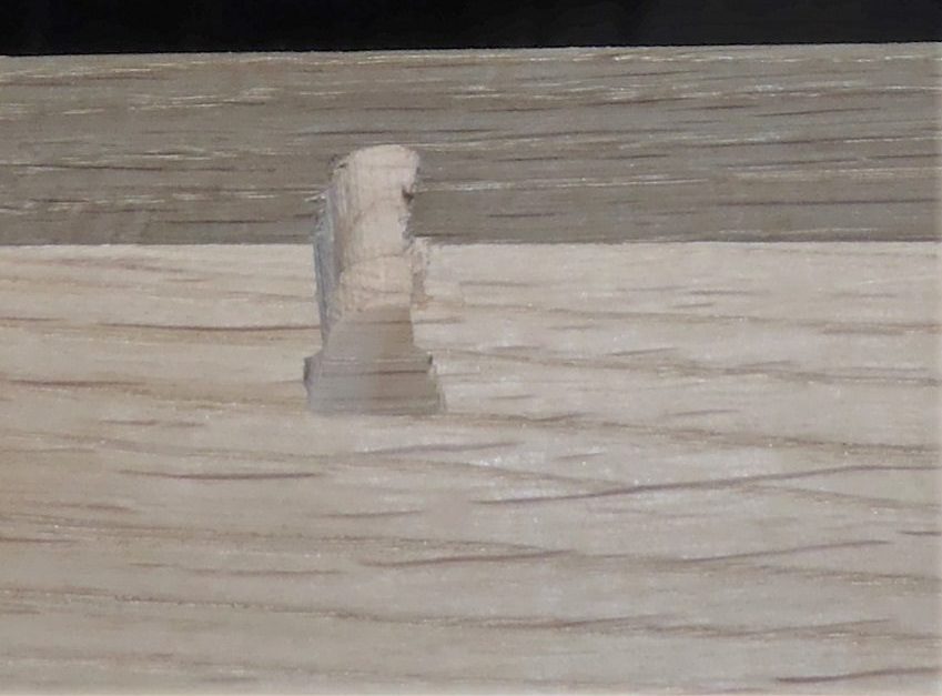
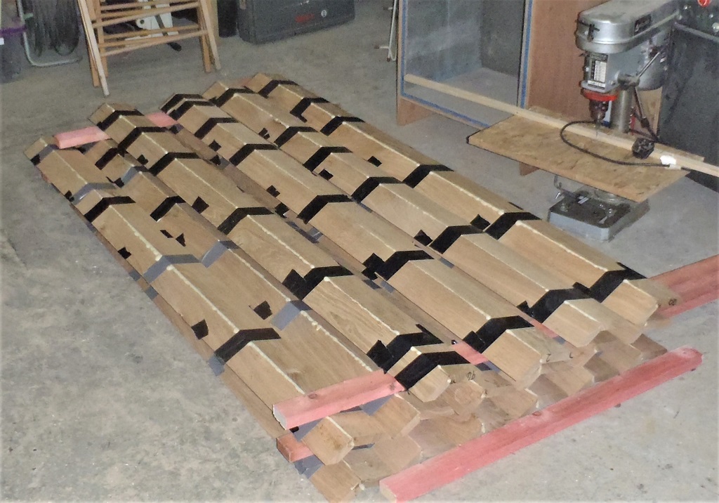
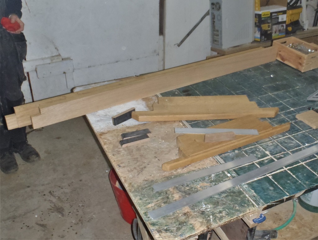
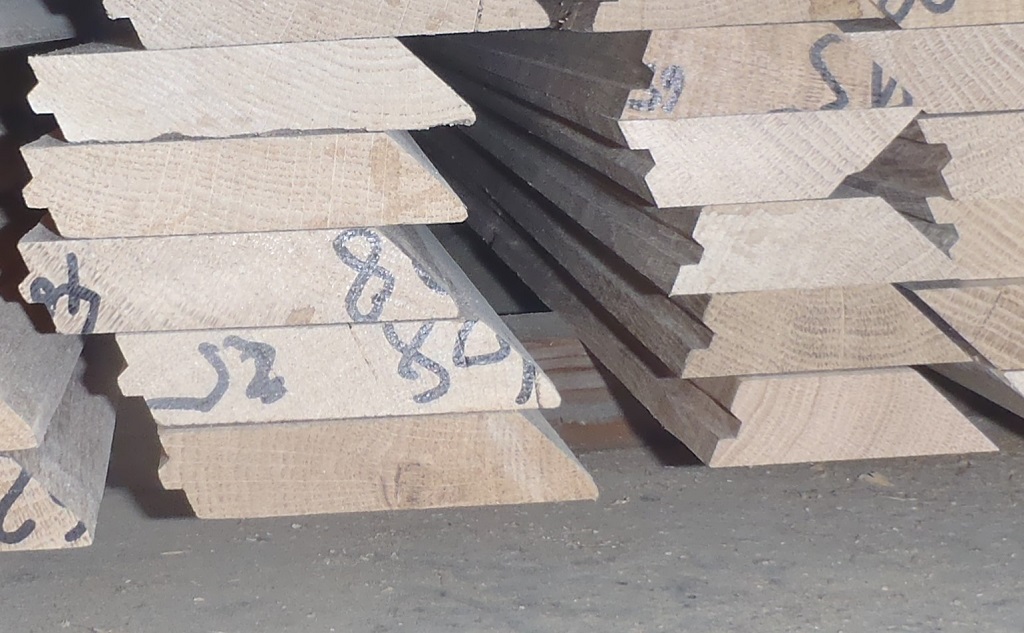
    Monday was the day we finished off gluing the octagon “wings” together and we now have a pile of 24 wings (and one spare just in case). They are not yet defined as left-handed or right-handed, they needs the bevelled sliced bottom ends to get them assigned into those two groups.

    Larch Cladding Timber Oiled and Burnt in Various Ways!

    Octagon-Wings


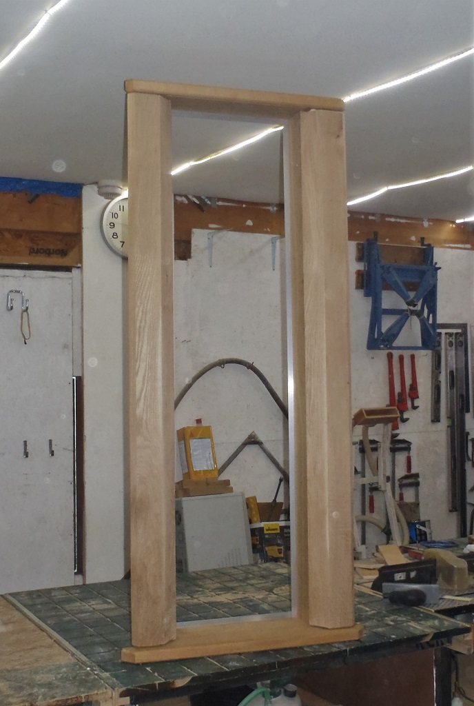
    But we want to make adjustments to our template device first before committing ourselves, and set the height of all the wings etc.

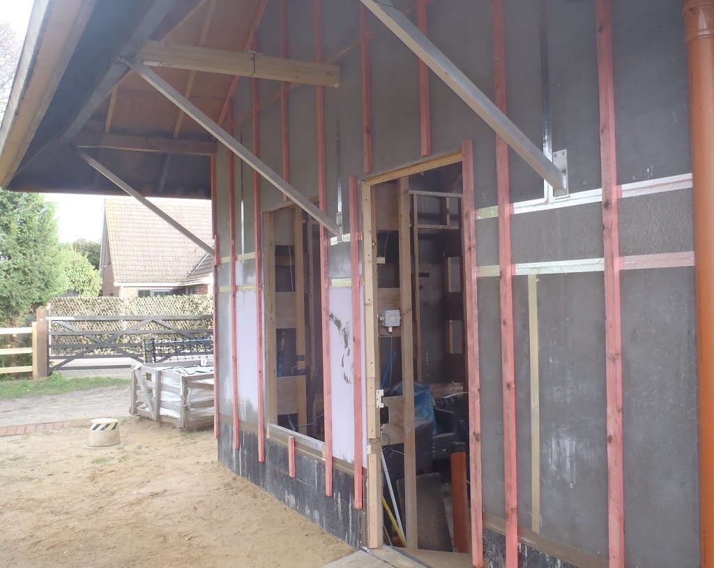
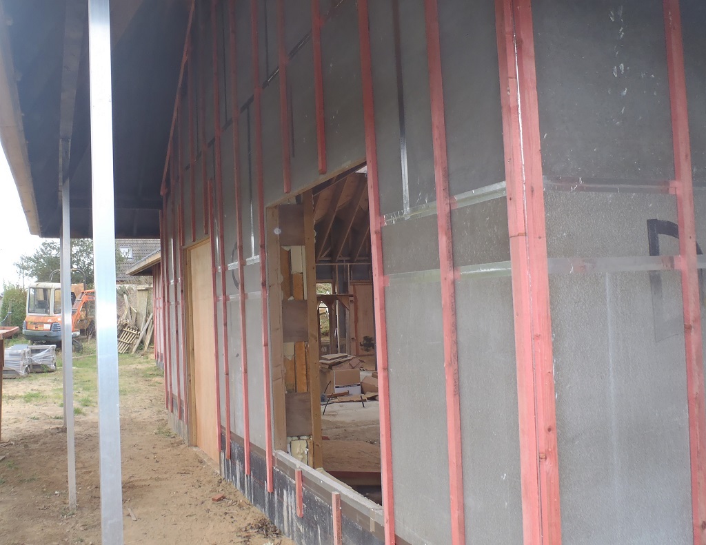
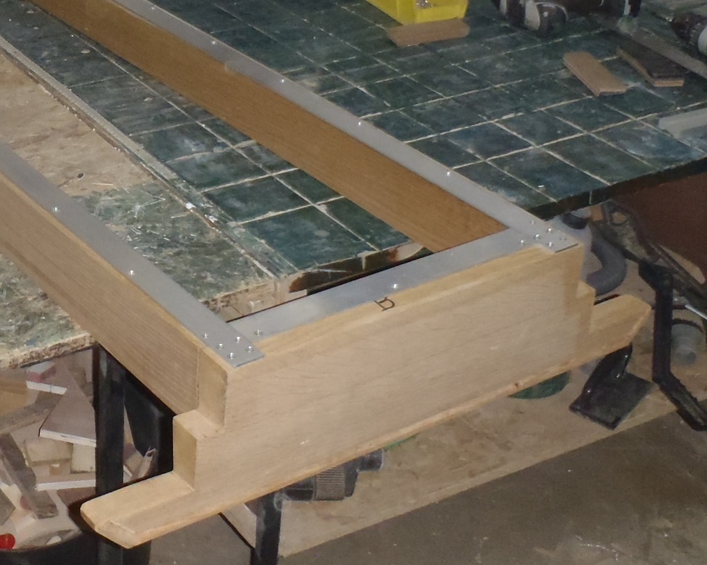
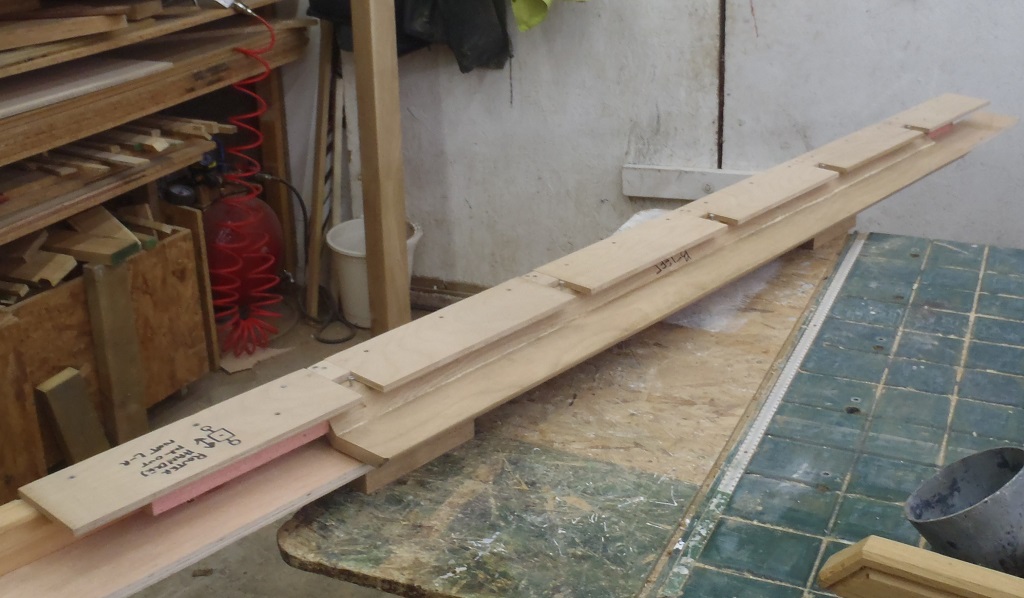
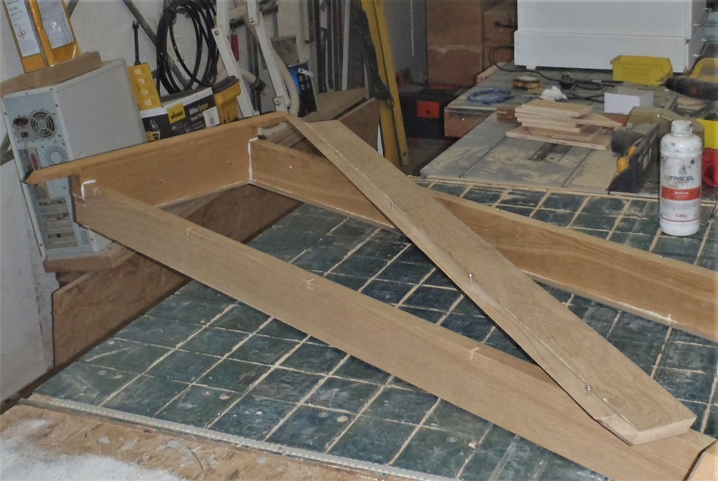
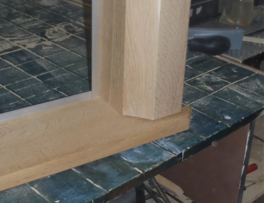
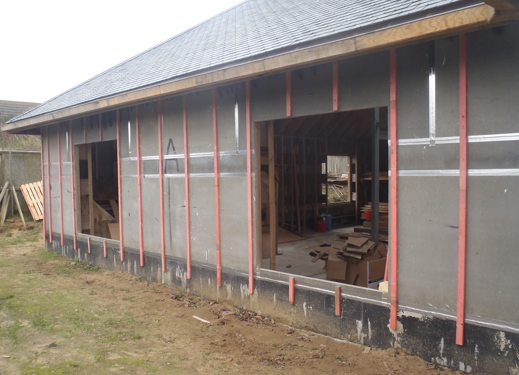
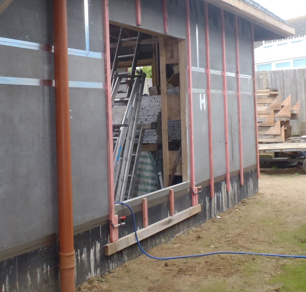
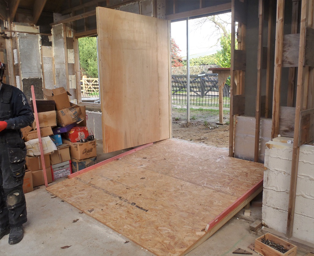
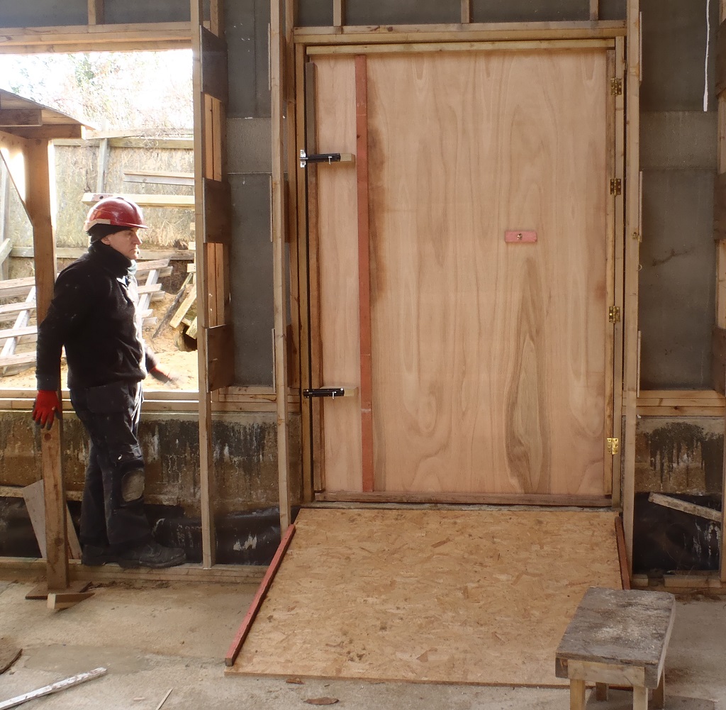
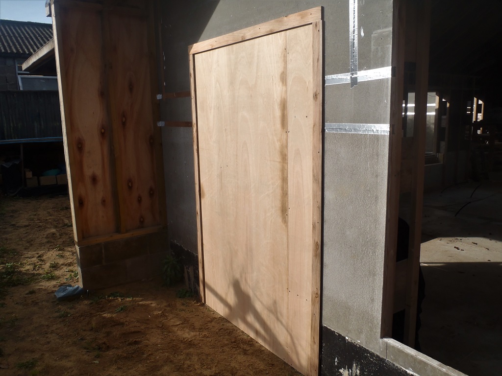
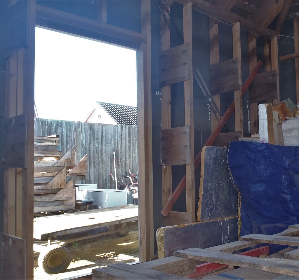
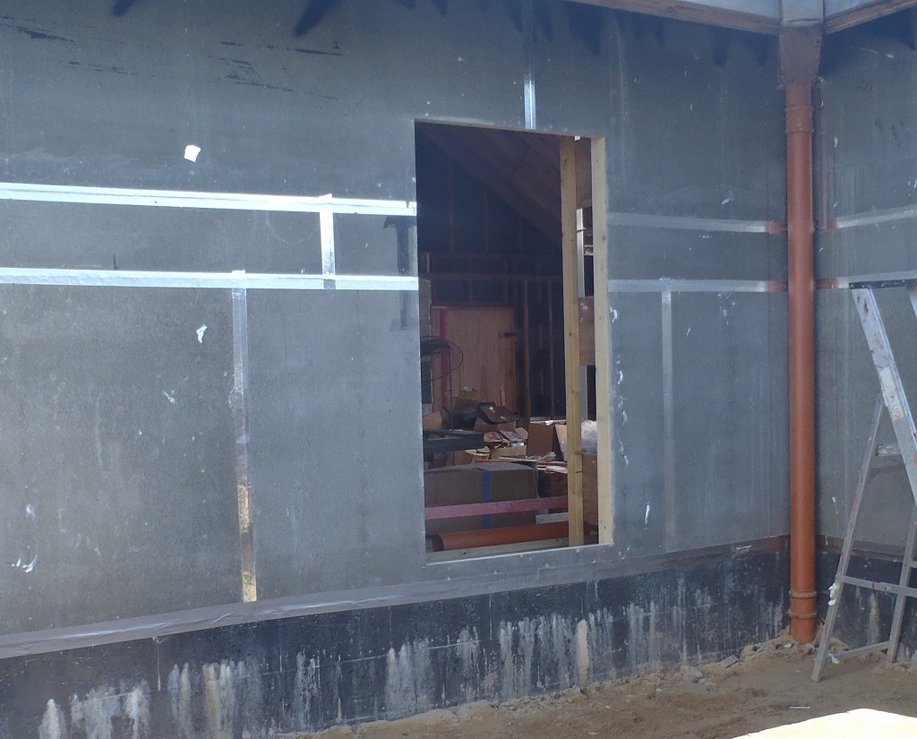
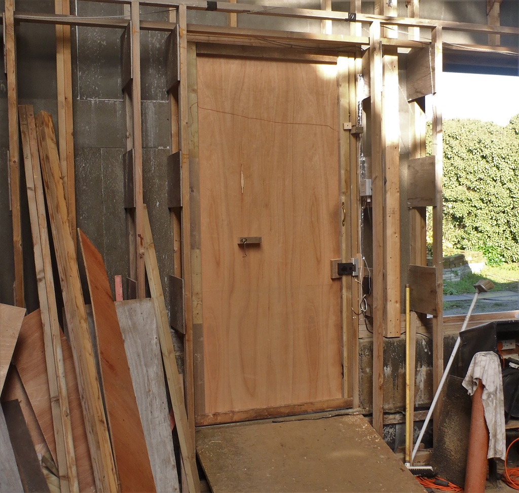
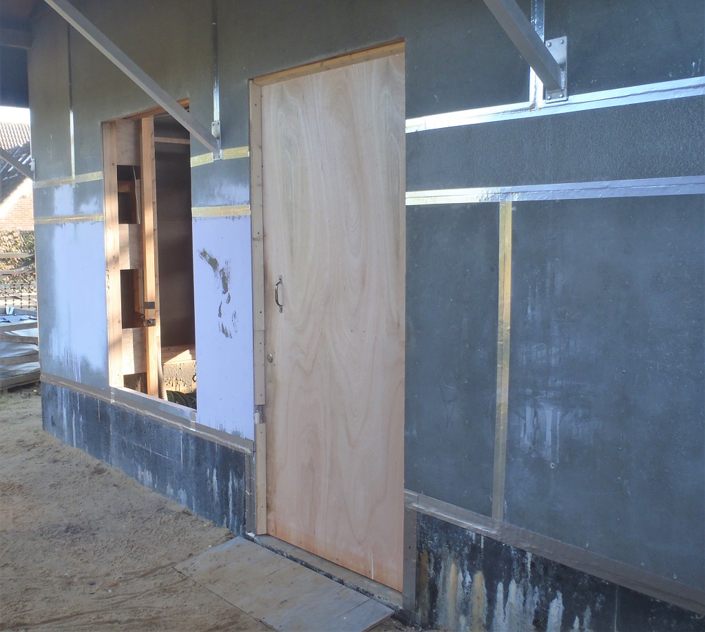
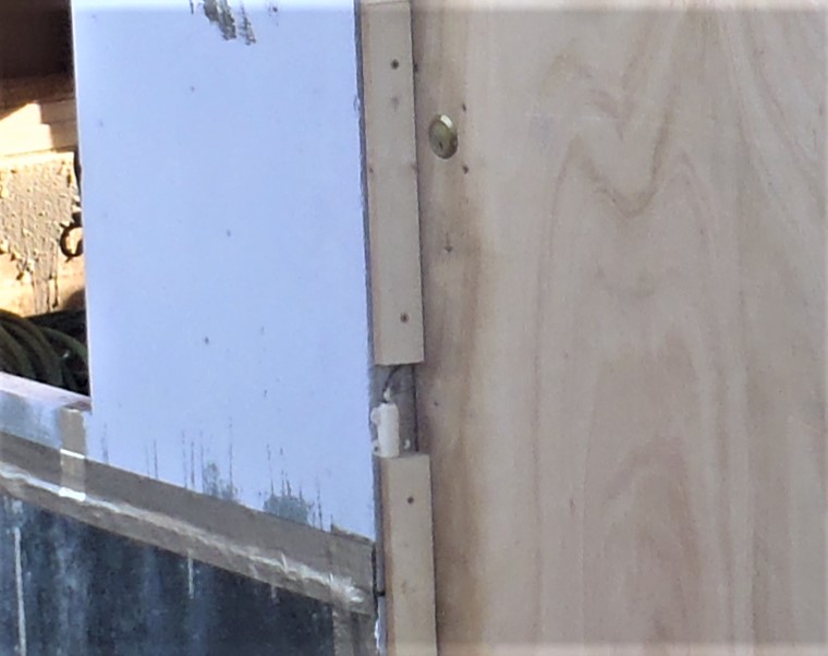
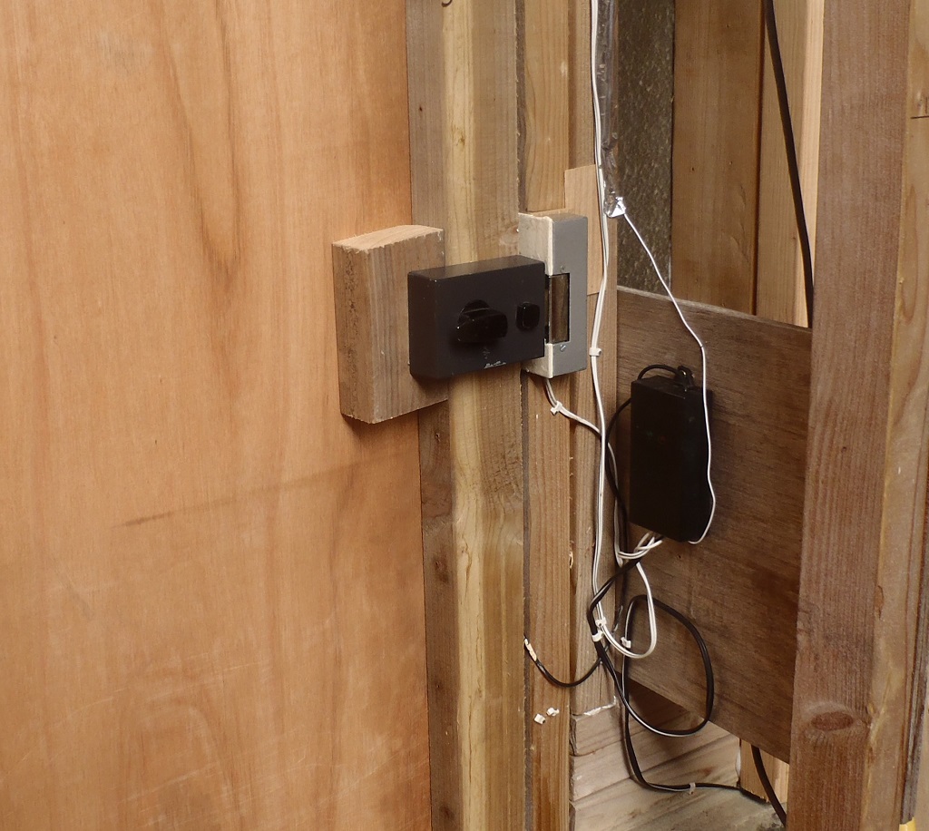
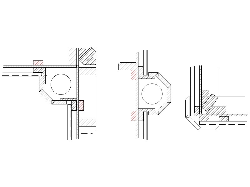
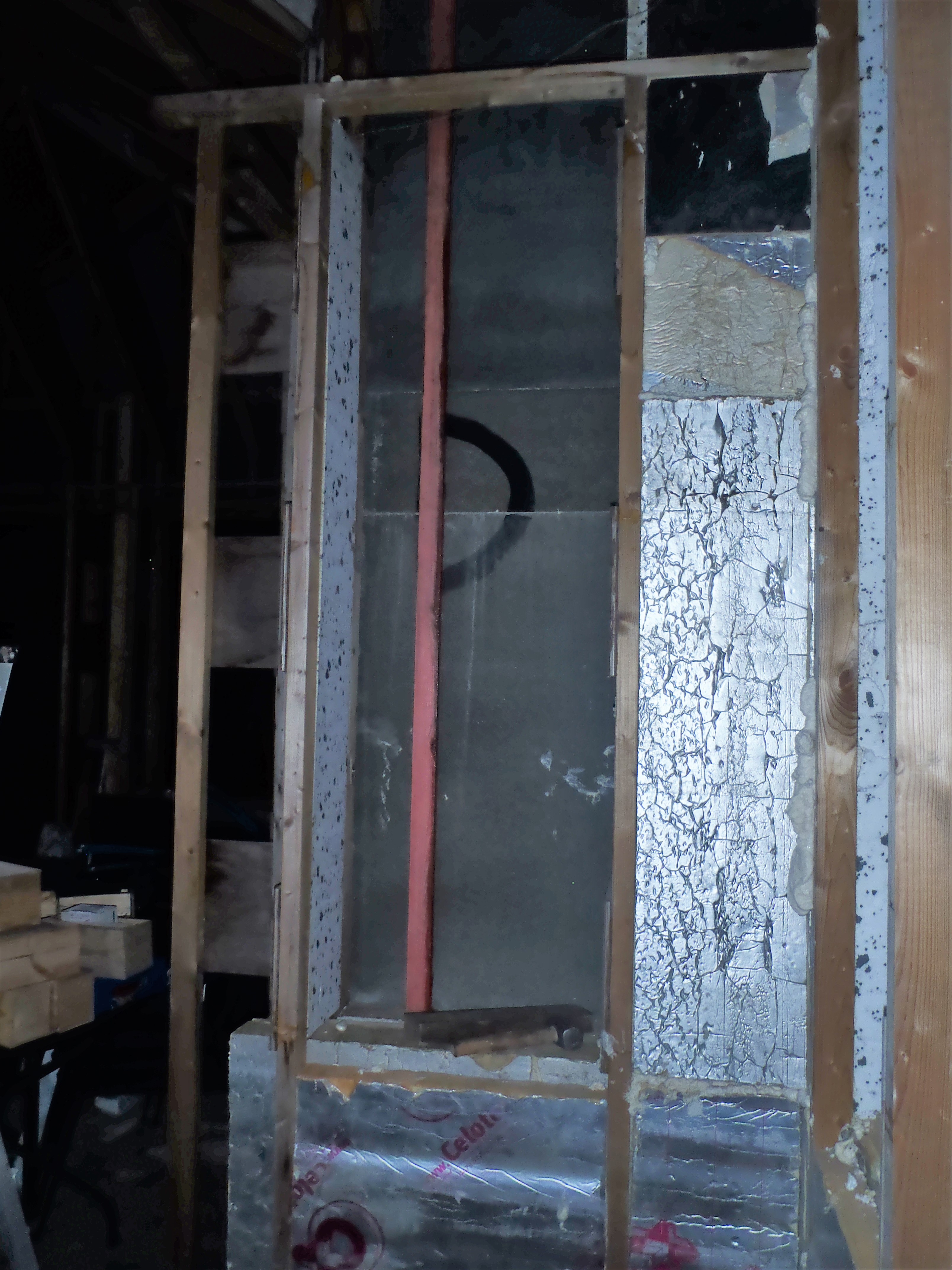
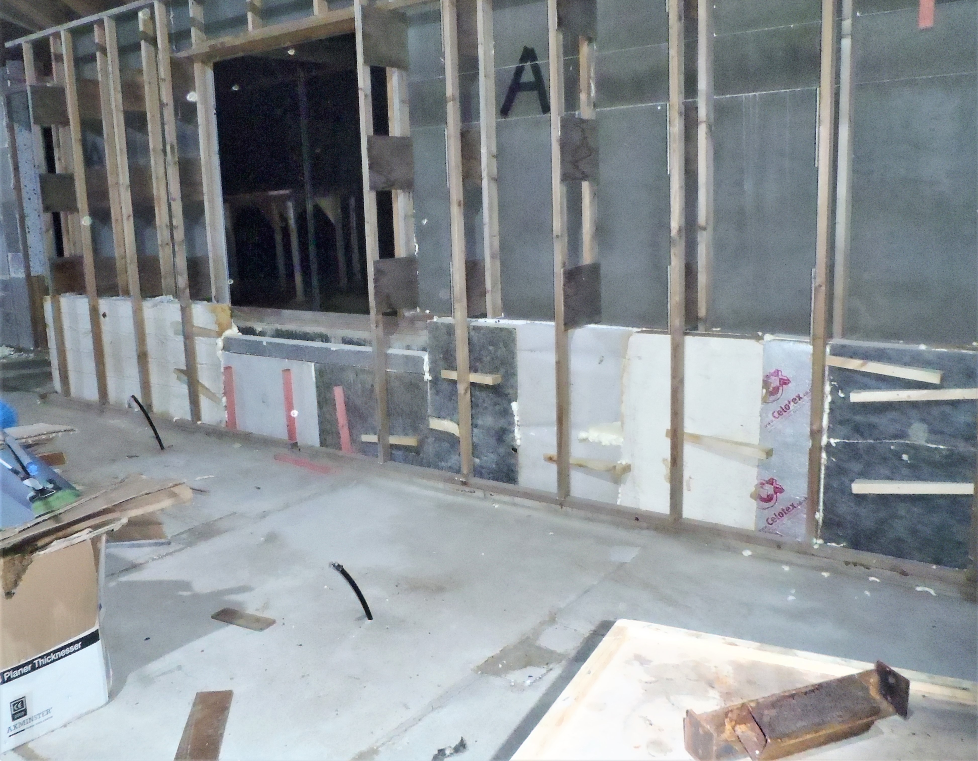
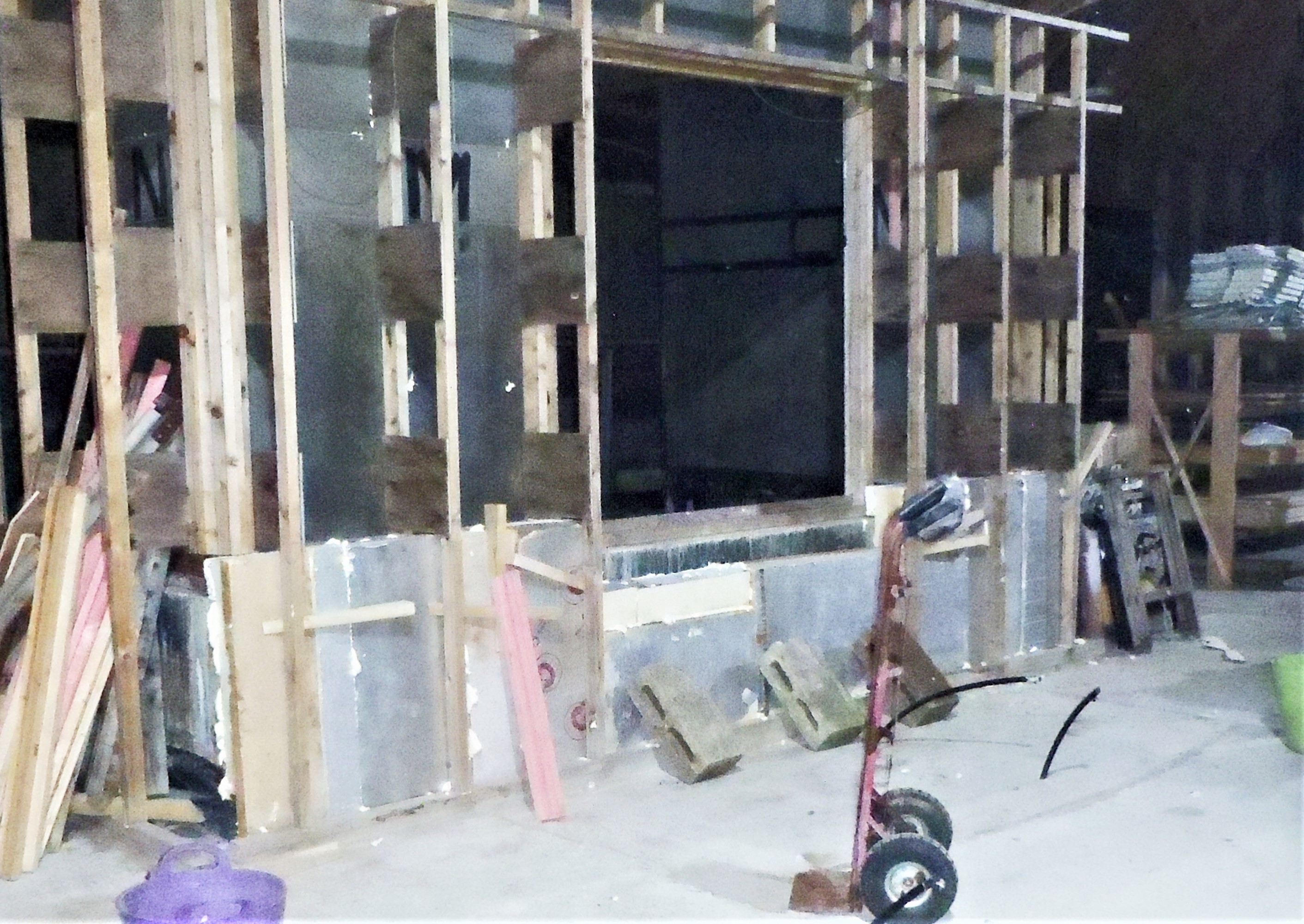
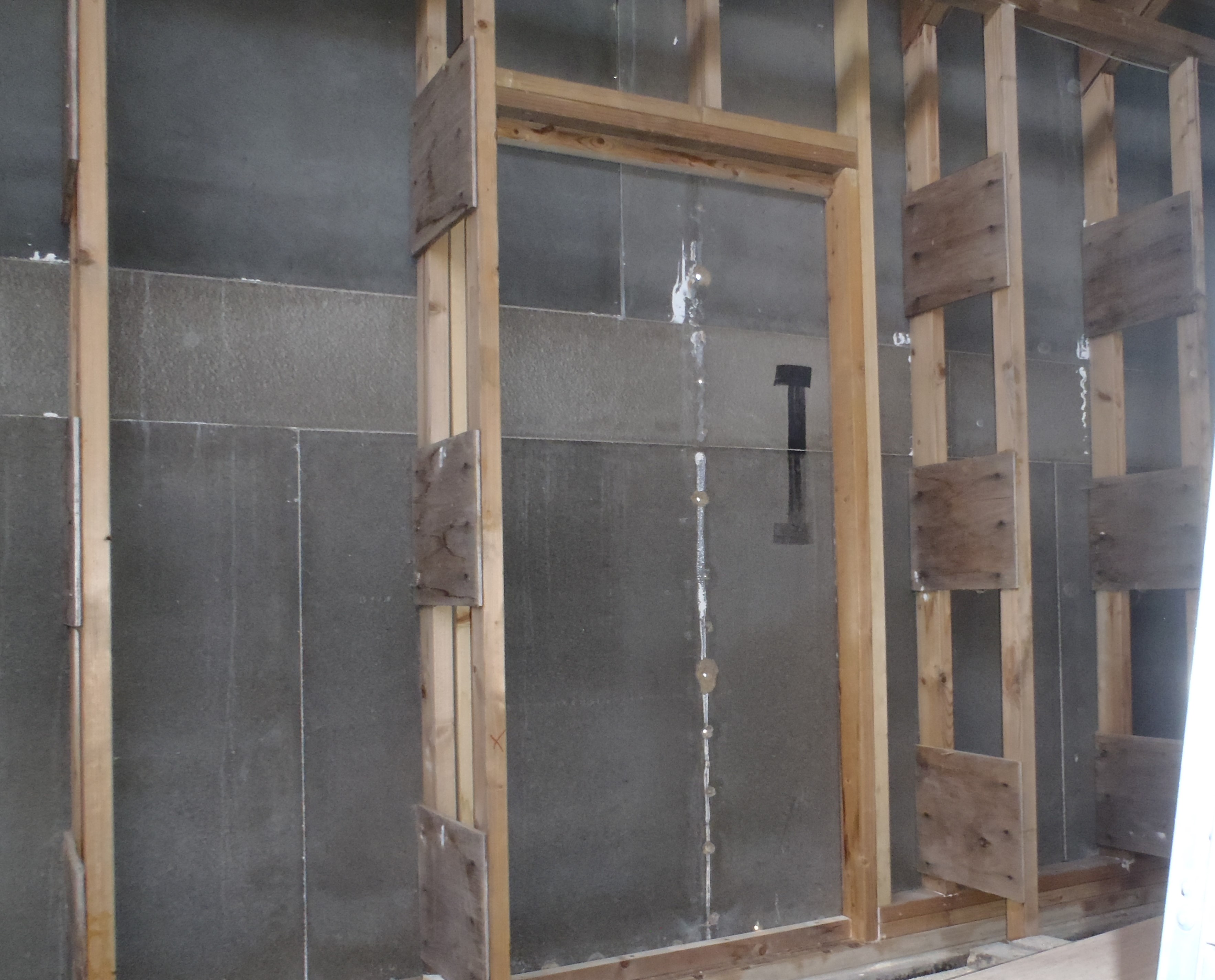
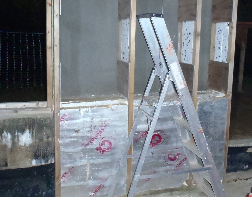
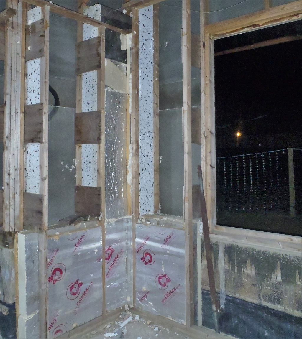
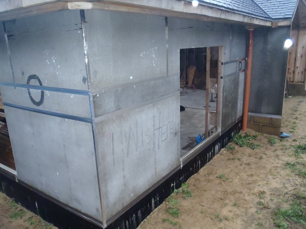
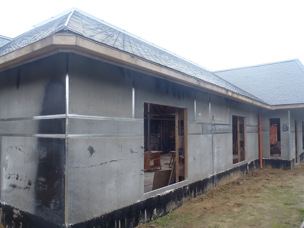
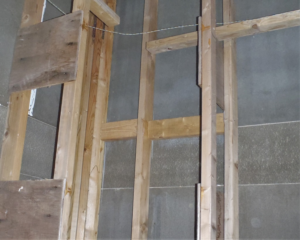
    In the meantime, we cleaned up the prototype (narrow) window frame of all the glue residue and tested it for solidness and carried it outside to see if fitted all our twelve holes in our walls. We discovered that the holes along the front of the building, the two side walls (the “P” and “H” sections) were able to take the window frame without trouble, with some millimetres of clearance, but along the back of the building, it was tight and even wouldn’t fit. It had been raining all morning and all day yesterday too, so the woodwork was likely to have swollen. This is not surprising and we can just sand the edges of the hole to get it to fit. We will also apply a 45degree angle chamfer around the edges of the hole too, to allow a decent quantity of sealant to provide a solid plug against rain water etc. and last a long time, even if the building wiggles in the wind, the seal will survive.
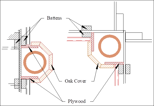
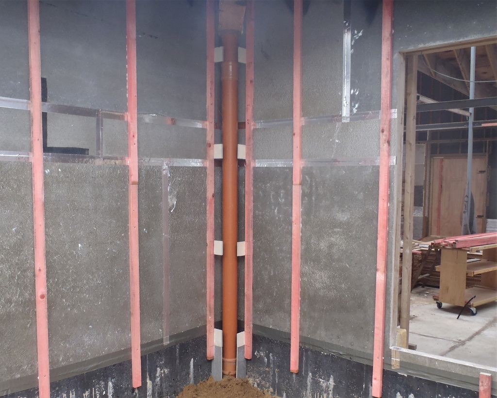
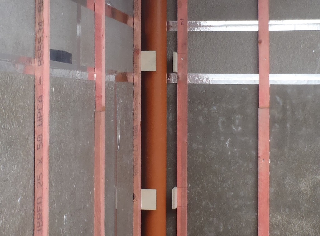
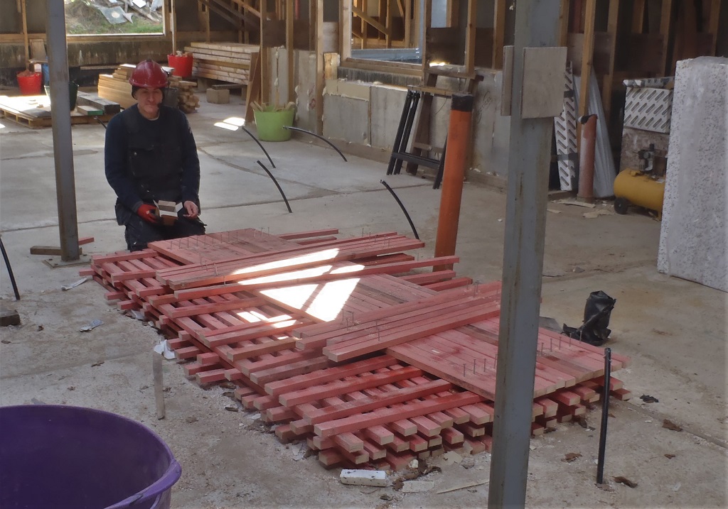
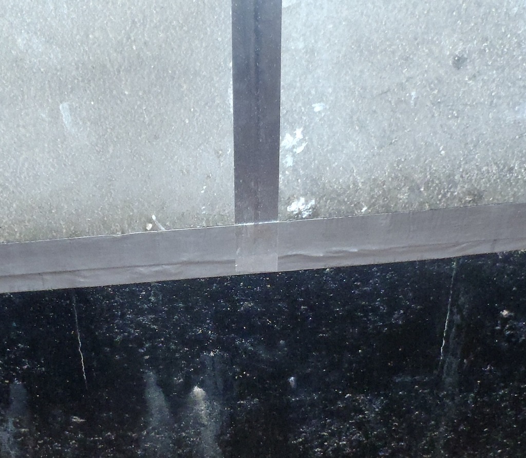
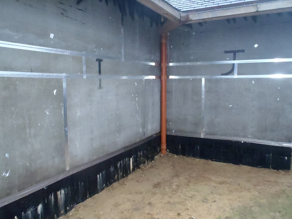
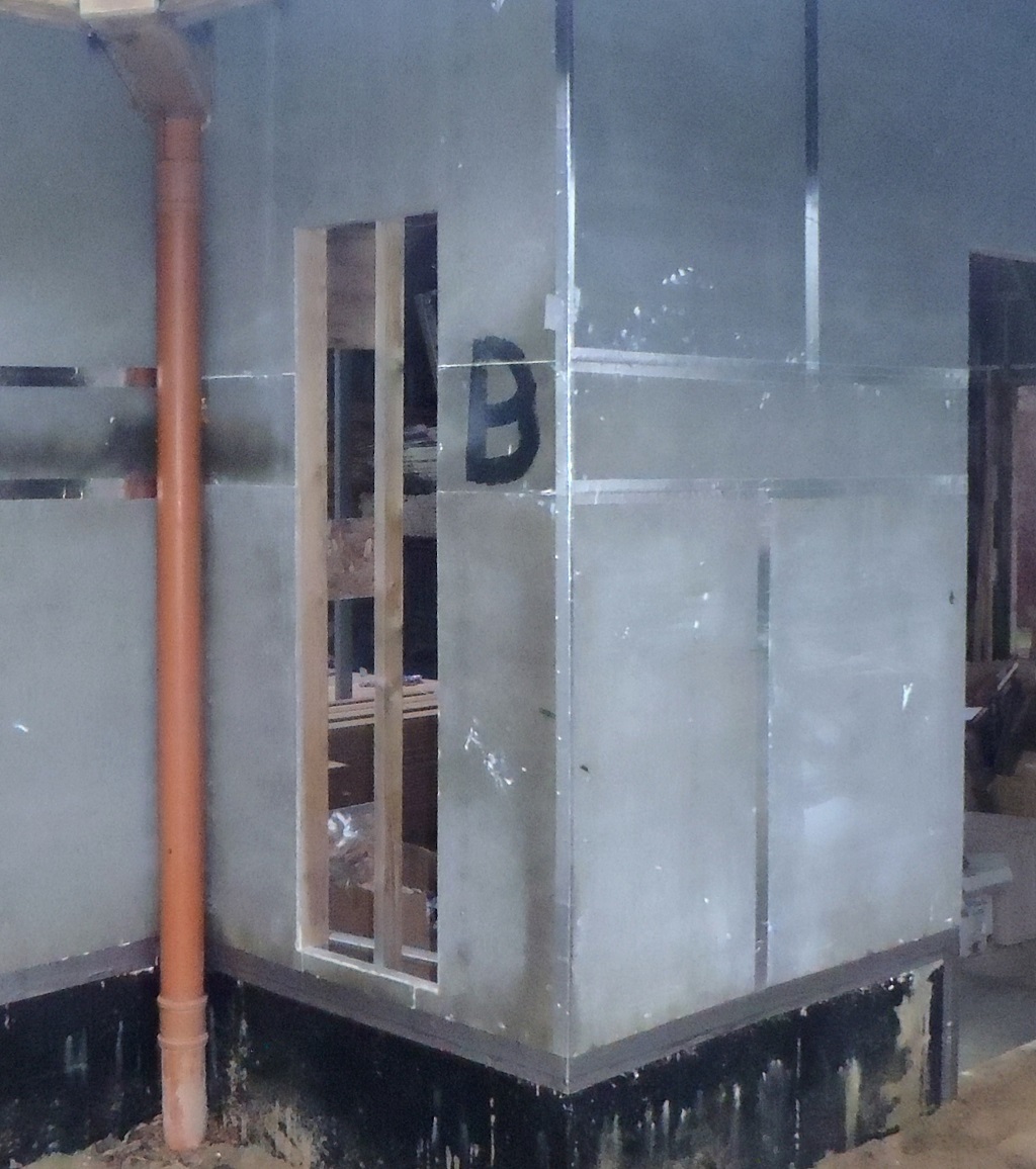
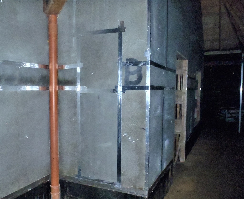
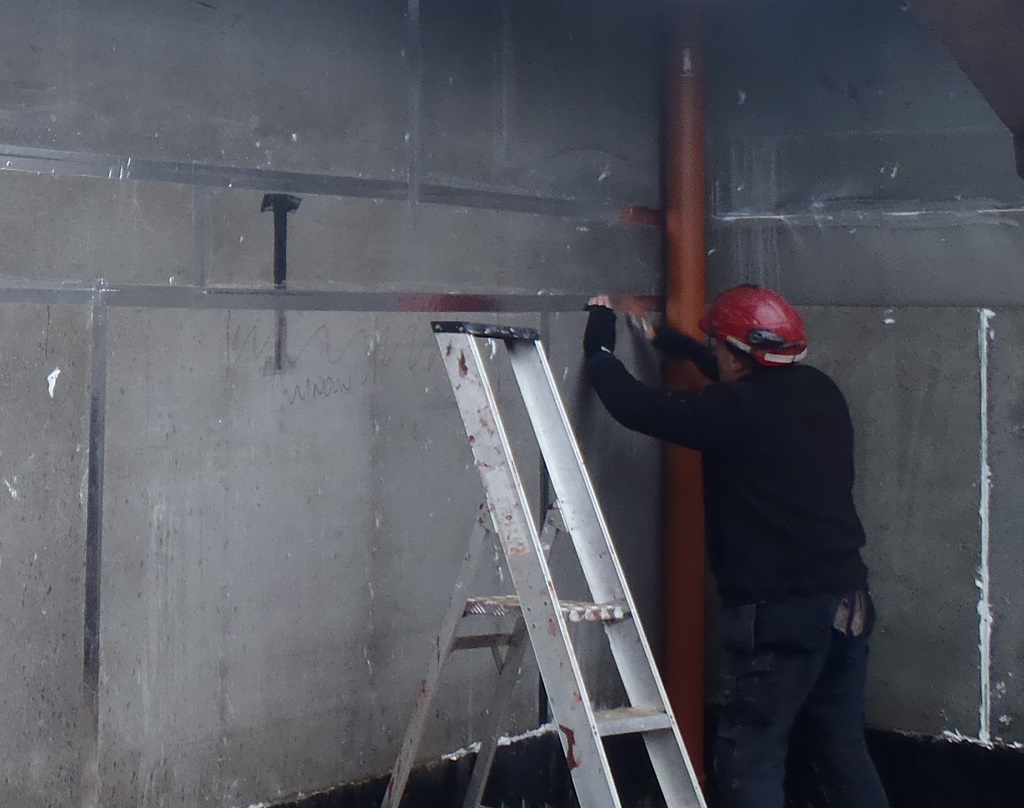
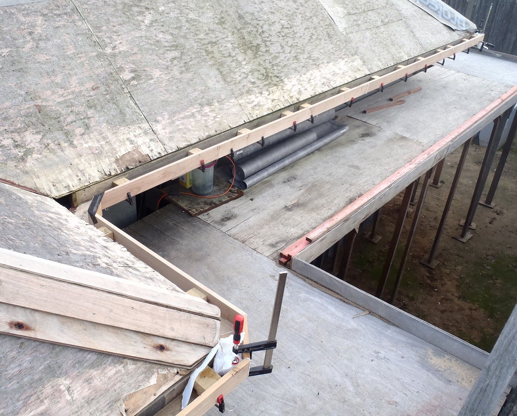
    The last job of Monday was to finish off putting the last odd three battens for the cladding, two of them around the “G” plastic downpipe

    Larch Cladding Timber Oiled and Burnt in Various Ways!

    Pipe-cover-support-battens-for-G


    And the final third piece for the “M-N” downpipe corner where we needed an additional batten to allow for a neat straight vertical line of fixing screws to hold the cladding in place. We also glued little short 200mm pieces on the side of the Porch beams on both the Front and Side door areas.

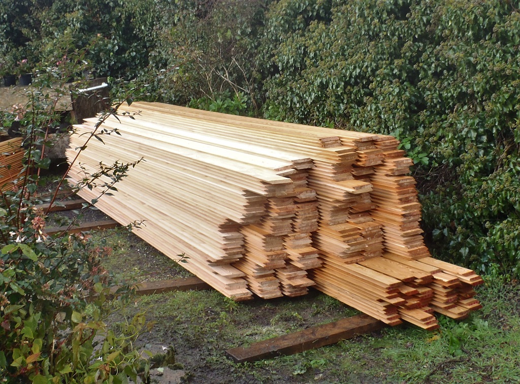
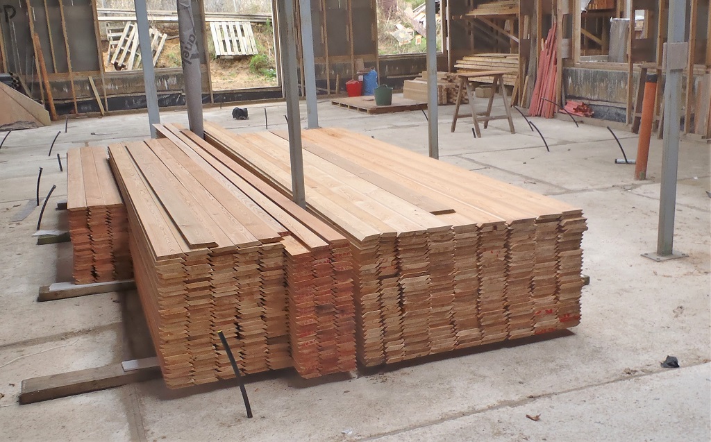
    Over the next couple of days, with some interruptions, we were testing the various timber treatment solutions; Fire Retardant, Timber Oil and the Timber preservative. We wanted to see how much and how slowly the liquid soaked into the test pieces of the Larch timber. It seems that the Larch is a dense wood material and it slows down the absorption rate. For example, leaving a piece in the liquid for 30 minutes, it only absorbed half the amount required to ensure the correct protection as provided by the special liquids, especially the fire retardant one. But if we dipped the timber in for a few seconds and then allow it to dry, repeat this step again another two times, we can reach the proper absorption levels. This is much better use of our time because we can go through our entire stack of timber with the quick dip and dry off in another new stack, and by the time we got through the 600 length of timber, we can start over on the first ones again for their repeat treatment.
    The Timber Oil is definitely slower as the oil is thicker and it does need more time than a few seconds, maybe a couple of minutes in a complete ducking, drain and then allow to dry. We think we then can repeat the process a second time and should also get to our required penetration levels to help protect against the effects of the Sun’s UV rays and general weather.
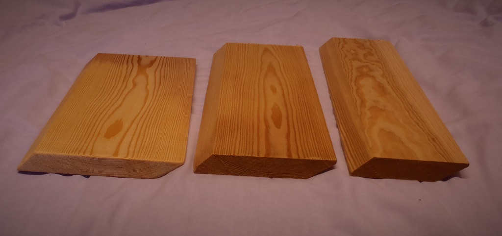
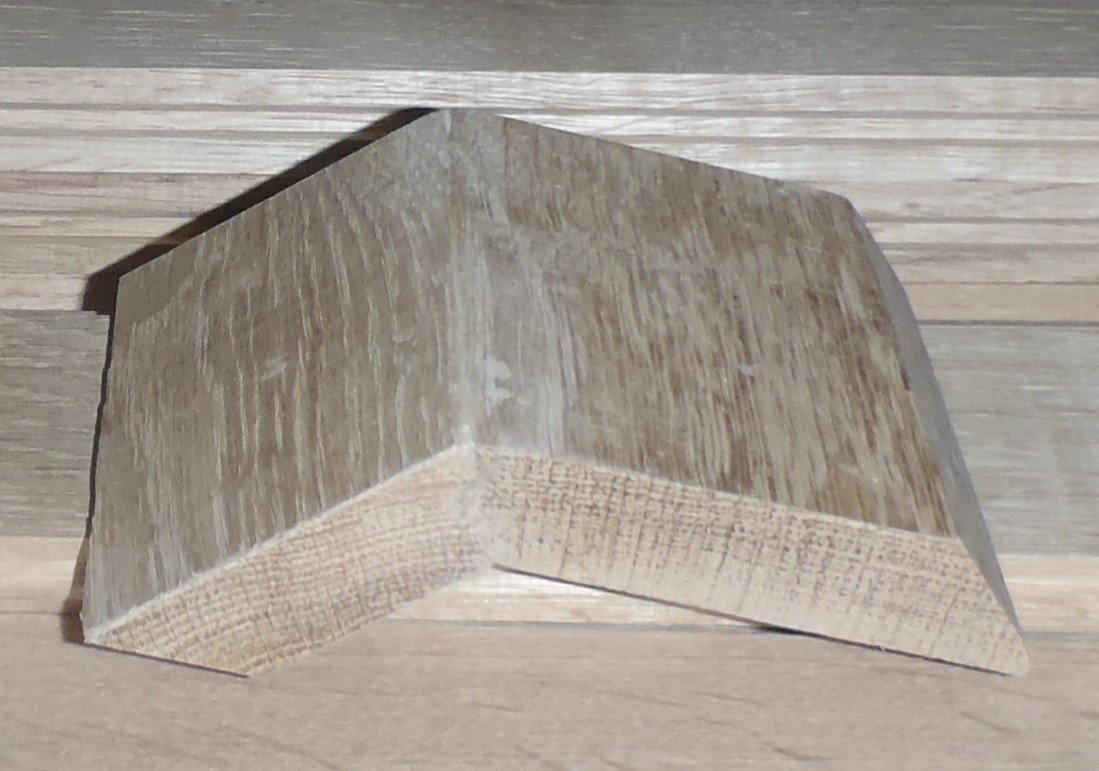
    The other area of testing was scorching the surface of the Larch, using a gas burner and then wire-brushing the carbon residues off. We did an initial gentle burn, a mid-level burn and a long burn.

    Larch Cladding Timber Oiled and Burnt in Various Ways!

    Larch-scorched-a-bit

    Larch Cladding Timber Oiled and Burnt in Various Ways!

    Then-wire-brushed

    Larch Cladding Timber Oiled and Burnt in Various Ways!

    and-finally-oiled


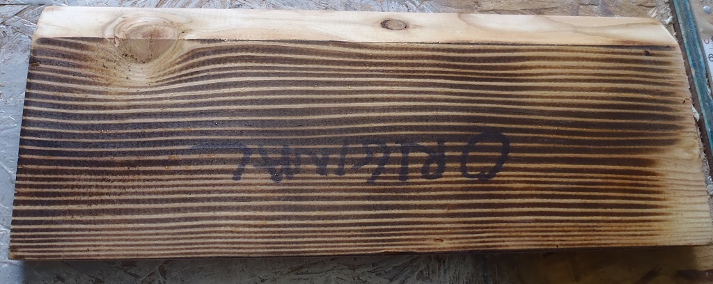
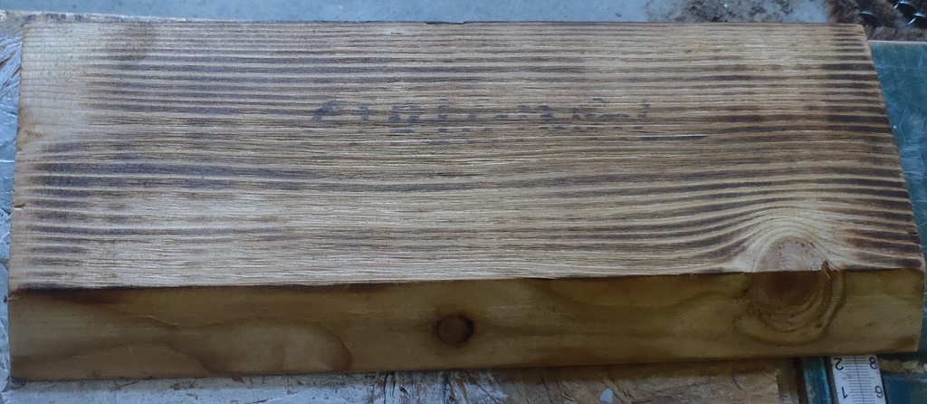
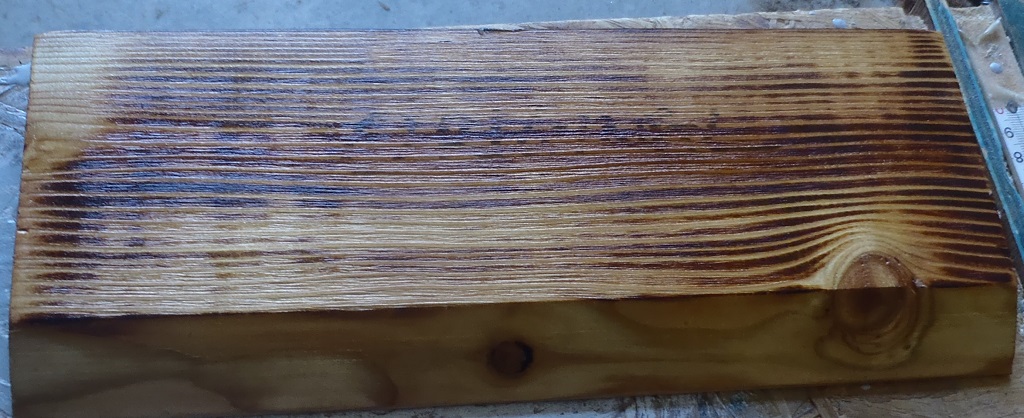
    Then started mixing up the combinations, to see the effects to the surface colouration when the liquids were applied in different ways.

    Larch Cladding Timber Oiled and Burnt in Various Ways!

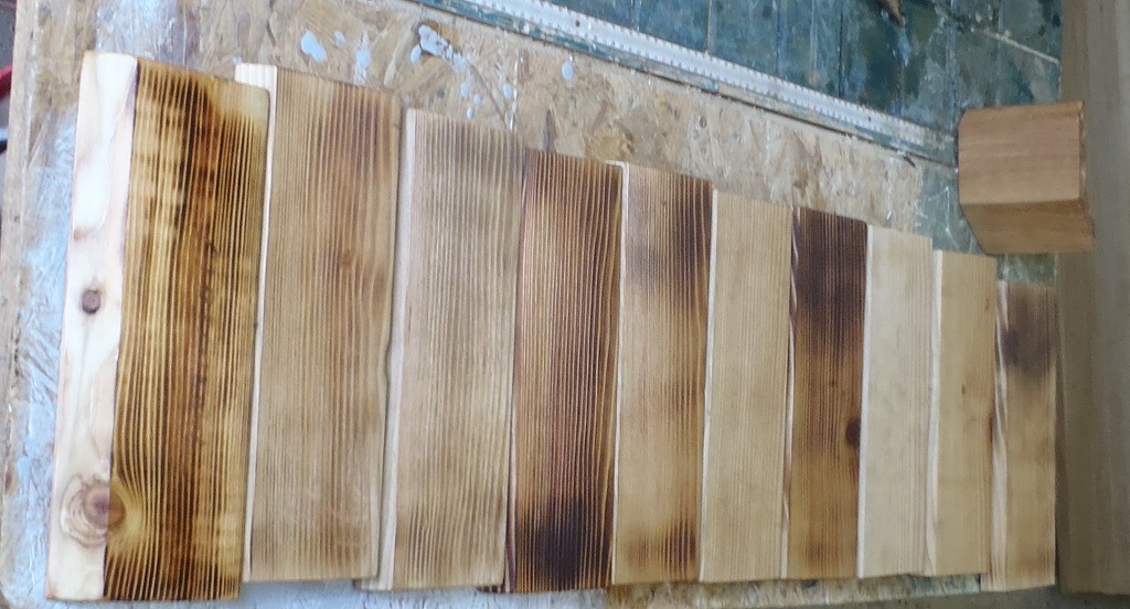
    The-diferent-test-pieces


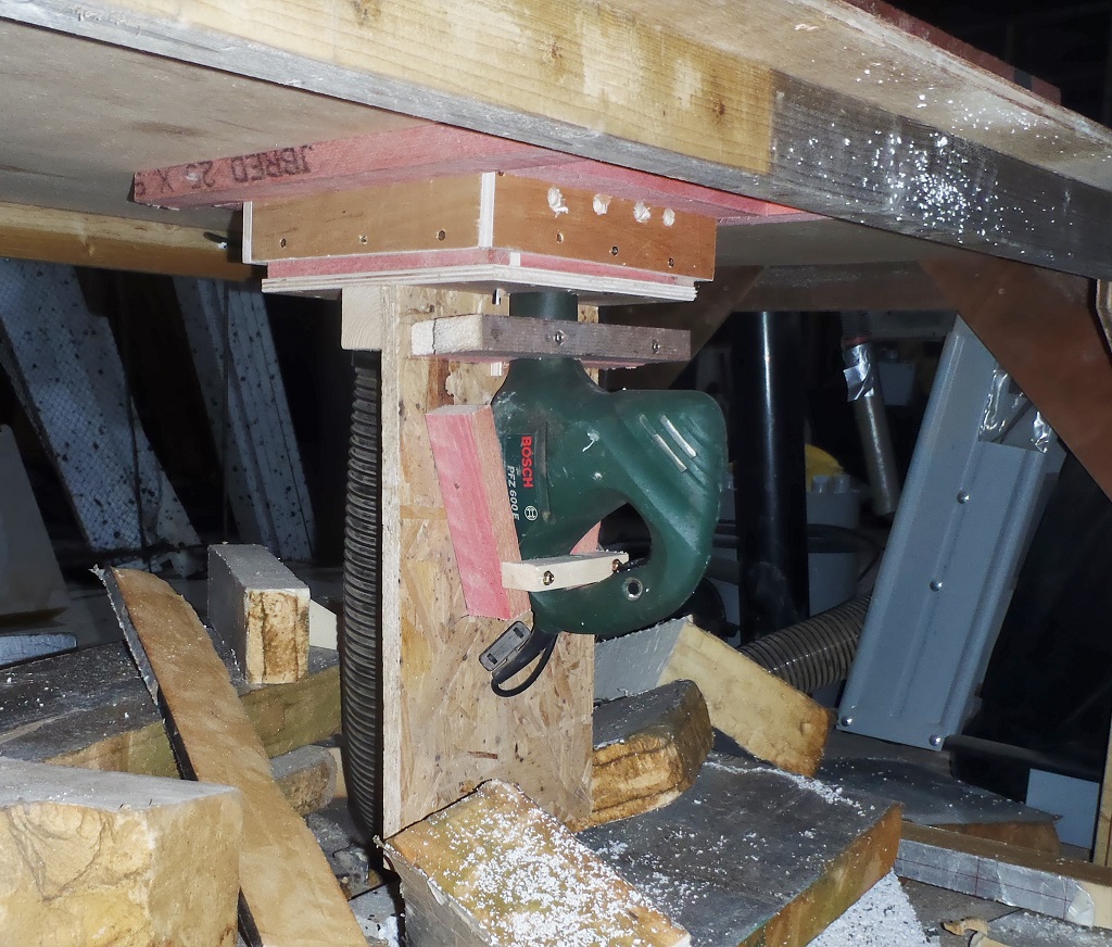
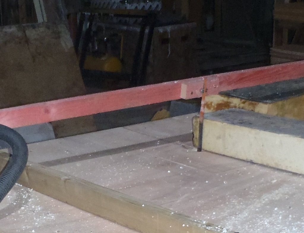
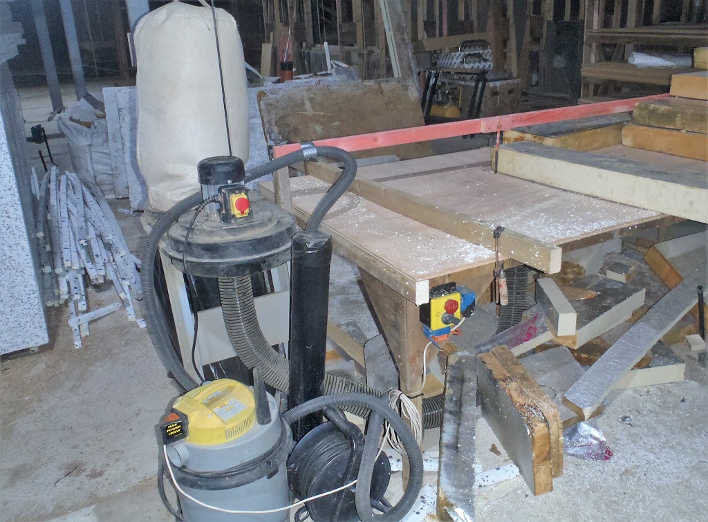
    We also started designing a mechanism where we will be able to put one plank of the Larch onto a set of rollers to guide the wood under a gas blow-torch and then through a spinning wire brush cleaner and pass a third roller which is there to slow down the rate of progress of the plank so we can get the desired scorching effects. We built our first version of the machine with the spinning wire brush ‘roller’ powered by a electric drill which had roller underneath which pressed the wood onto the brush and also resisted the forward motion of the wood from the spinning brush.
    Larch Cladding Timber Oiled and Burnt in Various Ways!

    Larch-processor-Wire-bush-on-drill

    Larch Cladding Timber Oiled and Burnt in Various Ways!

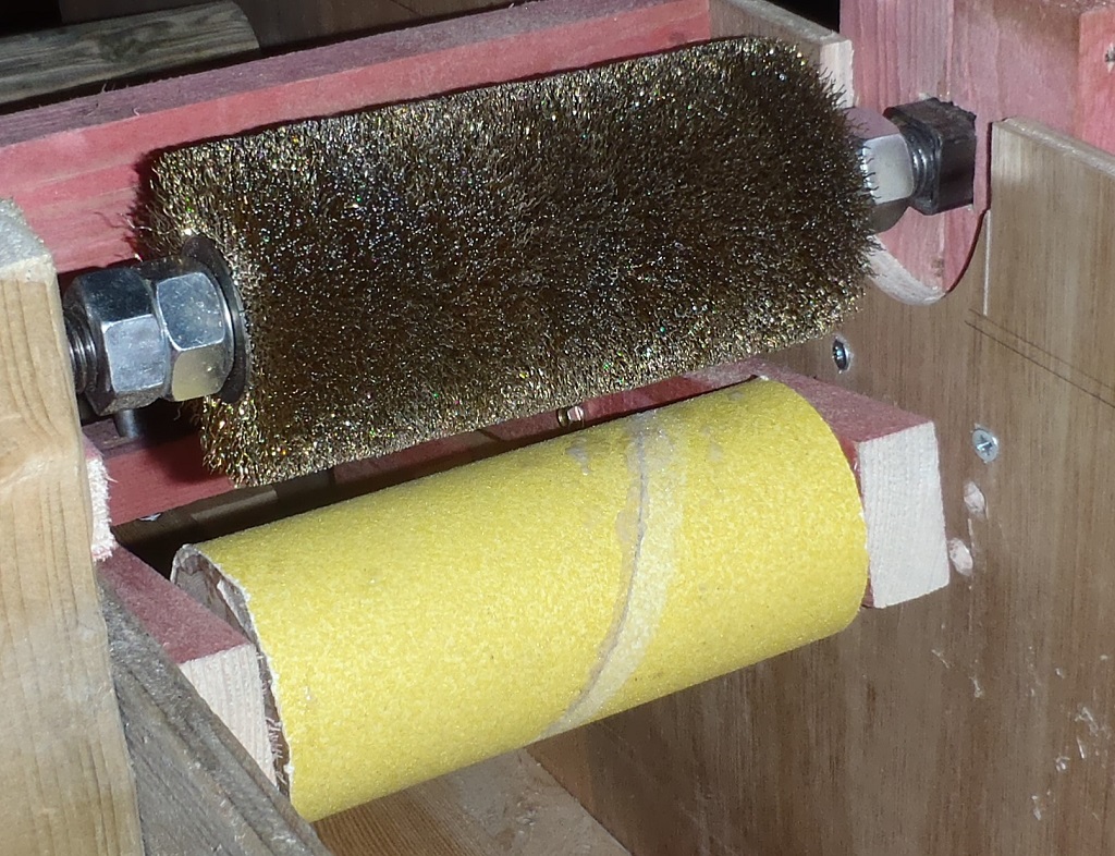
    Larch-processor-Wire-brush-and-friction-roller

    Larch Cladding Timber Oiled and Burnt in Various Ways!

    Larch-processor-The-first-try


    But after doing some test runs, using real lengths of our Larch timber, we discovered that our spiky wire brush cylinder won’t be able to cope with very slightly warped planks (the technical term is “cup”) and it would only scrub either just the middle bit, or just the two outer edges. We cannot rely on the Larch wood to be dead flat all the time. This puts our design of the Larch Scorching Machine under the spotlight again and come up with something else.

    In the meantime, we still can use what we have built, to mount our flame burners, pointing at the timber as it slides pass but we will need a different method of driving the Larch planks through the machine.
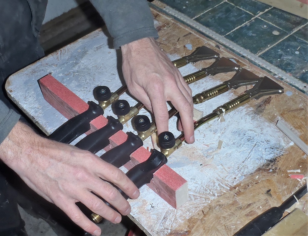
    Larch Cladding Timber Oiled and Burnt in Various Ways!

    Quad-blow-torches-


    The scrubbing task will have to be done manually, probably using the same wire brush cylinder but controlled by hand to cope with the warps etc.

    An odd job we did this week, on Friday, was to build our first space illumination device. We got a new supply of LEDs strips in which are mains powered directly off the 230V supply. It doesn’t need any transformers or other control units, just plugs straight into the mains socket. We wanted to have a couple of large space illumination units to help light up areas in the main house while we don’t have any built-in lighting units (especially after the first floor is in). The 20 metres of LED strips were cut up into 2 metres lengths and stuck to a plastic drain pipe. There are ten strips side by side, covering about half the way around the pipe.

    A Light 'saber'-Does not cut for sh*t

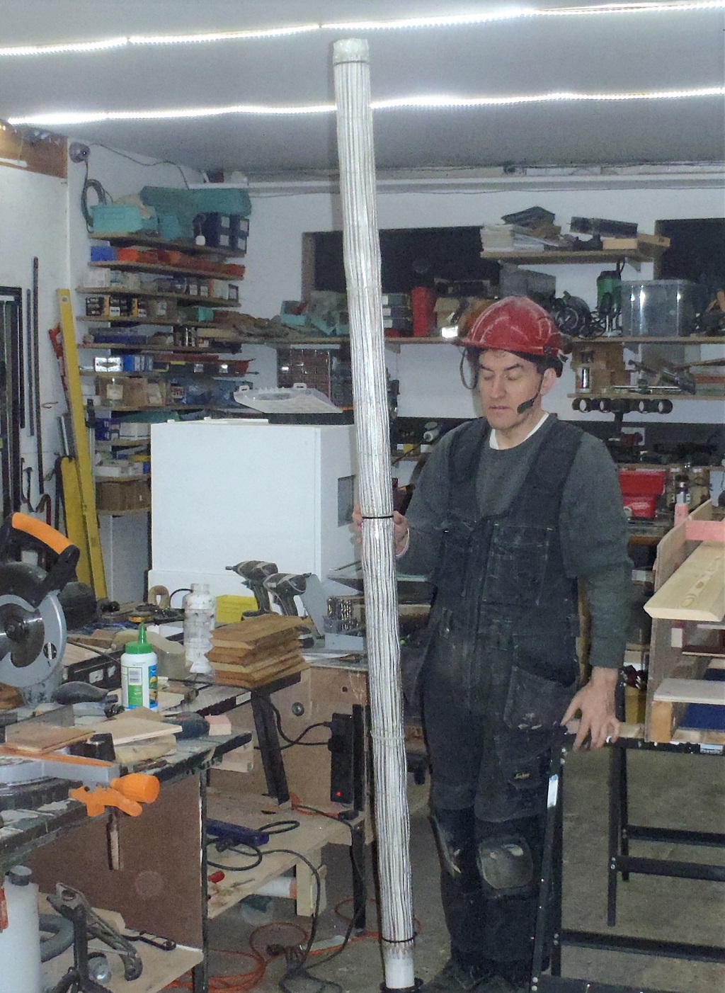
    A Light ‘saber’-Does not cut for sh*t

    Larch Cladding Timber Oiled and Burnt in Various Ways!

    even-when-turned-on

    Larch Cladding Timber Oiled and Burnt in Various Ways!

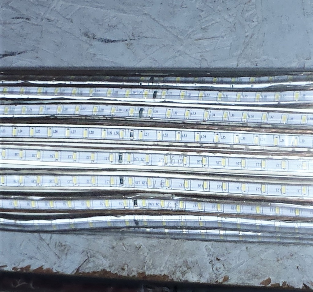
    Light-emitting-stripes


    These lights are tough so we don’t have to worry about damaging the bulbs or smashing glass covers on commercial lighting units, these strips are protected in a thick layer of rubber material. We will mount the tube to a paving slab as a base to make it stable.

    Next week, we will get on with our windows while we wait for new electrical parts come for our 2nd version of our scorching machine and perhaps, if we are lucky with the weather, we may even be able to put down the second layer of the black paint under our Eves too.

  • All Cladding Battens are Up and Oak Windows Jigsaw Coming Together

    We resumed the task of putting up the cladding support battens in, around and under the two Porches, i.e. the Side Door and the Front Door sections. We had to put in reinforcing internal battens going up the gable triangles before we could put on the battens on the outside. Oh yes, plus also, we put a set of diagonal battens just under the roof surface to provide fixing for all the angled ends of cladding pieces going up into the triangle. The doors had their own shorter battens because they were positioned independently of the standard 2 foot spacings.

    Back-door-gable-battened-1

    Back-door-gable-battened-1

    Back-door-gable-battened-2

    Back-door-gable-battened-2

    Front-door-gable-battened-1

    Front-door-gable-battened-1

    Front-door-gable-battened-2

    Front-door-gable-battened-2


    That was Monday and Tuesday that saw those sections done, we also cut up some 12mm thick marine birch plywood into 100mm square pieces and dunked them into the timber preservative solution, and left to dry overnight. Then on Wednesday, we proceeded to gather up all the battens we had previously allocated for the inner downpipe corners, making sure that we had the required 14 pieces, of which five had to be shorter ones that could only fit under the gutter channel itself. We put in the screw holes where there wasn’t one already, populated with a 80mm stainless steel screw and then spent much of the day, gluing and screwing four square plywood pieces to the narrow edge of each batten, 7 set of left-handed ones and the other 7 being a right-handed set. These plywood are sticking out away from the wall and will provide an anchorage fixing point for the Oak covering planks which hide the plastic downpipes.

    Pipe-Cladding-detail

    Pipe-Cladding-detail

    The last little job of Wednesday was to slice up some cement boards to make 100mm wide by 500mm long pieces, ready to be also glued and screwed to the bottom of the same battens to provide a very similar function but this time to support the bottom splash back slates running around at ground level.

    Pipe-cover-battens-with-plywood-attached

    Pipe-cover-battens-with-plywood-attached


    Thursday opened with the task of finishing off the preparation of the cement board strips by cutting them into 500mm lengths and then got outside with a spade, our collection of cement board pieces, a pile of screws, tools and our prepared battens. We dug foot down little holes either side of the plastic downpipes, glued and put in a single screw to hold the cement board pieces on the edge of the batten, positioned each batten up to the line we had already drawn several weeks ago and then glued plus screwed it into place. The cement board hanging down went into the soil and packed around it to secure it into place.
    Pipe-cover-battens-installed

    Pipe-cover-battens-installed

    Pipe-cover-battens-details

    Pipe-cover-battens-details


    We got that done by lunch time, and in the afternoon, we resumed work on the Oak window frames in our workshop. We implemented our plans by first drilling holes in each aluminium strip, a set of holes 3mm in diameter with a counter sinking attachment fixed to the drill bit so both the hole and clearance for the screw is drilled at the same time. Each hole is 7mm from the edge and spaced apart by 160mm. Some of the ends had extra holes to be firmly fixed to its sibling oak frame. Then we went along screwing on the aluminium strips to the four frame pieces and achieved our first look at a (nearly) completed window.
    Window-assembled-for-the-first-time

    Window-assembled-for-the-first-time

    Window-aluminium-strips

    Window-aluminium-strips


    Friday’s job was to design a jig structure to hold the two long vertical frame pieces so we could cut a special “T” slot into the side of the timber, ready to receive a screw or bolt that will be attached to the removable “octagon wings”  on our windows and doors.

    T-slot-for-fixing-Octagons

    T-slot-for-fixing-Octagons-e1582471933186

    How-the-Screw-goes-into-T-slot

    How-the-Screw-goes-into-T-slot


    We performed some tests and then went for it by cutting five T slots in each side piece. We had to use two router machines to achieve the end results as the special T router bit wasn’t longer enough so we had to cut a precursor slot first using a ordinary straight cutter bit and then used our T shaped cutter afterwards.

    T-slot-and-Screw-jig

    T-slot-and-Screw-jig

    The last job of the day was to take two sets of our octagon wings and get them glued to form the section of the octagon shape and have them ready for the next day.

    The last day, Saturday, we took those octagon assembled pieces and adapted our jig framework to allow us to drill a pilot hole into the interfacing surface, get a screw in and then slide the whole thing on to our window frame. After some more testing of position of this pilot hole, we proceeded to do the five holes in each of the “wings” and put in the stainless steel screws and fitted it all together.

    T-slots-on-frame-and-Screws-on-the-Octagon

    T-slots-on-frame-and-Screws-on-the-Octagon

    Window-frame-completed-1

    Window-frame-completed-1

    Window-frame-completed-2

    Window-frame-completed-2


    There was a lot of fiddling around of course, and we got to a point that we have learnt several things about our completed prototype window frame. For example, we saw that we had cut off too much of off the height of the octagon wings because there was too much of a gap at the top. Also the two wings were not quite aligned, having slightly different gaps at the bottom between the wings and the sill. We want a gap but only a couple of millimetres to allow the rain and moisture to be blown away and keep the timber fresh and dry. These wings are not to be permanently fixed to the window frame as we want to remove them to service the cladding in some future years, so we need to ensure long life the timber material, hence having a good circulation of air in and around all the timber materials.
    We have written down all these results and we will make adjustments when we get to cut the next batch of the octagon wings sometime in a week or two.
    In the meantime, we had gone through the entire stack of our octagon pieces, tidying up “bad” ends and cutting every one to a uniform 1650mm long. Ultimately we are going to cut them to a more precise length, including the bevelled cut to match the slope of the bottom sill too and to the height of each window as we make them in turn.
    The final last part of the day was to start gluing and holding together a batch of the octagon wings. We managed to do 16 of them before we ran out of PU glue. We got a further 8 to go to complete the set of 24, to go with our 12 windows we have in the house.
    Lots-of-window-Octagons-glued-up

    Lots-of-window-Octagons-glued-up


    So next week, we will continue with that task, but also start investigating ways of oil treating the Larch cladding timber, including the fire resist treatment as well, plus also, sorting out the slates that provide the flashing protection between the dirt and our timber cladding. Oh yes, We do have one more downpipe still to do to put battens around the plastic pipe, namely the “G” point next to the Side Door – mustn’t forget that!!

  • Cladding Battens are affixed to Walls

    We got on with the work we left standing on Saturday, which is putting up the cladding battens onto the walls, ready for installing the Larch cladding.
    We proceeded by drilling clearance holes top, bottom and middle of each long piece and just top and bottom for the shorter ones. Also the shorter ones were dipped into the timber preservative solution to ensure long life.

    Cladding-battens-cut-and-drilled

    Cladding-battens-cut-and-drilled


    The first wall we tackled was the two back sections, “K” and “O” and after confirming where the bottom of each batten comes down to (overlapping onto the concrete block) and double checking with another batten on another section, we were happy that things were consistent. We used lots of PU construction glue to stick each batten to the cement board, lining up over the nails (fixing the cement boards to each leg) and then screwing down tight the three (or four) stainless steel 70mm long screws.
    First-lot-of-battens-on-KLMNO

    First-lot-of-battens-on-KLMNO


    The rain (and one heavy thunderstorm shower) interrupted this process so we got on with predrilling the rest of the battens, dipping the cut ends in the preservative and distributing the battens to various sections around the house. We made extra ones where needed and we also realised that the inside corners where the downpipe channels lie, we need an additional batten to allow us to fix the ends of the cladding around the boxing of the rainwater channels.
    After a another day of other commitments plus also rescuing a friend’s pergola that was nearly blown down by Storm Ciara ..
    We resumed work Wednesday on putting up the battens on the outside of the house walls. Applying the PU glue and fixing them down using our stainless steel screws, we managed to get all of the “K”, “L”, “M”, “N”, “O”, “P1”, “P2” and “A” sections done before it got too dark .. and blooming cold too!!
    All-battens-on-A-wall

    All-battens-on-A-wall


    Upon the next day, Thursday, with the heavy rain showers in the early morning fast disappearing off over the hill, we managed to get the rest of the walls done with the first set and largest bulk of battens to go up. We had to make some rearrangement of certain battens as we saw that we needed longer ones for particular walls, especially the ones that has porches sticking out. Then, we got on with sorting out the smaller pieces for above and below the windows, drilling holes into the thirty or so pieces and then dunk them into the timber preservative and having them distributed to each window around the house, ready to be installed on Saturday.
    We made a simple guide tool to ensure that the small pieces under each window are aligned up to their longer siblings on either side of the window.
    Aligning-battens-under-the-windows

    Aligning-battens-under-the-windows


    With Friday lost to external meetings again, we resumed on Saturday and finished putting up the smaller pieces of battens underneath and over above each window. The small piece under the window is so small that it needs a concrete screw to be used in place of the traditional wood screw so we had to drill a 5mm hole into the concrete blocks and then screw a 70mm long concrete screw.

    The rest of the day, after lunch, was spent in the workshop (to keep out of the way of Storm Dennis!), to start designing and implementing a set of methods to allow us to assemble our Oak Window Frames in a controlled manner, to achieve exact measures and angles, namely, nice and straight and square! We tried out various screws, counter-sinking tools and methods of drilling and screwing into the oak. We also cut four pieces of our aluminium strip so we can put together our test window frame (it was our old narrow window that we have abandoned), this strip is 3mm thick by 38mm wide and we also tested what will work with aluminium as well.
    It was all spent in doing lots of tests and discussions, in ways of mounting the metal strips to each piece of the Oak Framework, in what order and so on.

    Parts-for-window-assembly-testing

    Parts-for-window-assembly-testing


    We would carry on with the aluminium strips and oak pieces if the weather is wet and horrible, but for the last part of the task of putting up the cladding support battens, these being inside the two porch sections and we will tackle that job next week, depends on what Storm Dennis brings!! Fingers Crossed!

  • Temporary Doors and ramps for the Three Doors

    After skipping Monday for other commitments, we got on with making doors and ramps for our three entrance ways in our main house.
    We finished off the Front Door, putting on the hinges, filing wobbly edges and then mounting the door into place. then putting on door jams. We also put on two sliding security bolts and a little hook to keep the door fixed open when we are using it.

    Front-door

    Front-door

    Front-door-and-ramp

    Front-door-and-ramp


    Then, we got on in making the ramp and door for the Conservatory door, which is a very similar size, except that we decided the ramp only needed to be 4feet long, hence it is steeper. We won’t be delivering much building material that way into the house. So the ramp is 1550mm wide by 1220mm slope.
    The door is slightly different as we wanted the door to be flushed to the outer surface to try minimise the amount of rain water that may be flown on to the wall and door. This door doesn’t have the same protection (at the moment) compared with the Front Door and the Side Door.
    So it was made of two vertical 89mm CLS timber pieces and two 63mm CLS pieces for the horizontal top and bottom edges and the same whole sheet of plywood plus a little strip to make up the total door width of 1490mm. It was the same height of 2240mm.
    It was assembled all together and mounted into the frame, using our two little air bags that can be pumped up to lift each side up or down to get it positioned just right. the four hinges went on ok and then put on outside rain guard strips over the joint and discovered that the door wouldn’t close any more.
    So on the following day, we put in some spacers behind the rain shield strips to loosen the grip on the door and as an extra accommodation, we also sliced off another 5mm off the width too. All is good now. We then put on two sliding bolts and a hook to secure the door and hold it open respectively. Oh yes, we also put on a rain deflector at the bottom of the door. The whole door then got two coats of a green all weather timber protection paint, to keep off the rain water and stop it absorbing into the plywood and delaminating the layers.
    Conservatory-door-inside

    Conservatory-door-inside

    Conservatory-door-outside

    Conservatory-door-outside

    Conservatory-door-open

    Conservatory-door-open


    The next job was to install additional racking elements on the inside framework of the “I” wall where we had put in a new window. Because that corner of the building could potentially have the full force of the wind unimpeded and the new window meant that the wall is a little bit weaker so the extra racking elements were required. We put on two metal bands diagonally from the bottom right corner, going up across three legs before reaching the top plate. We also installed a stiff rigid element going diagonally in the opposite direction, from the top left down to bottom left, up to near the new window. This was a piece of wooden batten, glued and screwed into place.
    Cross-bracing-on-I-wall (lot's of dust reflecting the flash)

    Cross-bracing-on-I-wall (lot’s of dust reflecting the flash)


    Now we could remove the cement board from the window to open it up. The heavy duty outer was employed with a half inch cutter and went in the clockwise direction to slice away the excess cement boards. We now have a new window hole ready for the Oak sill (which fitted nicely) and the glass.
    Window-hole-in-I-Inside

    Window-hole-in-I-Inside

    Window-hole-in-I-Outside

    Window-hole-in-I-Outside


    We cleared away all the ton bags of insulation foam pieces (two bags of those) and a further 3 ton bags of oak trimmings from our planing of our oak timber. They are all tidied up alongside the “I” section including the slicing table too.

    The last job we got to start, was making the third door for the Side Door, which is only 1030mm wide by the usual 2240mm high. We used just the 63mm CLS timber pieces, laid flat around the edges and put on just two hinges (the door is much lighter) and got it mounted onto the wall frame. The last quick job was to put on a door hook to hold it open during the night and stop it swinging in the wind.
    Upon the following day, Thursday, was putting on the door jams to limit the swing through the wall and then mount an electronic locking mechanism with a remote sensor to pick up the little portable badges.

    Back-door

    Back-door

    Back-door-outside

    Back-door-outside

    Back-door-lock-sensor

    Back-door-lock-sensor

    Back-door-lock

    Back-door-lock


    We can now open the door easily without having to use a traditional key and even while we are carrying something! SO we now have three doors fitted and when we got the windows installed, we will have a secured building which will allows us to store more equipment in there and not worry so much about items being nicked.
    The final couple of days were spent preparing for putting up the larch cladding to the walls. We needed to fix internal bracing battens to reinforce the cement board so when the external batten is installed, it got something far stronger and more secure to hold the external batten up against the wall. The inside corners, where we have the gutter’s downpipes located, need these extra battens. So we did the 7 corners around the house and screwed on 13 pieces. We had already put one up last week when we were doing the foam insulation.
    Next, we calculated the length of the external battens we would need, coming down from the rafters and stopping 200mm off ground zero. But because there are three set of angles on our roof (32, 40 and 45 degrees slopes), each batten is slightly different in length. So after analysing each wall, and their windows, we had a list. we set up the chop saw and put together end-stops at each required distances, and proceeded to make 42 pieces at 2740mm long (14 of them were made from two left-over lengths), a further 20?? pieces at 2730mm long and finally 19?? pieces at 2710mm long. All these are full height battens but we need shorter ones that goes over the windows and also underneath as well. The calculations came up with a further 7 pieces at 730mm, 5 at 710mm and another 4 at 700mm long for above the windows and 19 lengths at 290mm long for underneath.
    That pretty much concludes the week’s work. We can start on gluing and screwing each batten into place next week.

  • Continuing Insulation into Walls

    At the start of the week, we needed to make sure that we had all the required cladding support battens in place, especially around the drainpipes. The cladding needs something to screw into and it turns out that the walls don’t have anything on the inside surfaces (it is just a single 10mm thick cement board) to provide a firm mounting point for the external vertical batten in and around the downpipes.
    We analysed the drawings plus we also measured all the downpipes outside on the house, to find the worst case, and make sure that our Oak Octagon covers will fit around the downpipes and have something secure to fix on to.

    There were three specific areas to analyse, the outer corners, the inside corners (containing the downpipes) and a special case of a downpipe in the middle of the “H” wall. we drew each Oak Octagon cover and this led to providing measurements to where to put these extra support battens.

    Oak corner and pipe covers

    Oak corner and pipe covers


    The last part of the day was to draw lines either side of each downpipes to where we need this batten and then drilled clearance holes ready for us to screw into place the internal battens (2inch by 1inch).
    We screwed in the extra batten for the “D” wall ..
    Extra-Batten-to-hold-the-Oak-corner-Cover-

    Extra-Batten-to-hold-the-Oak-corner-Cover-


    .. so we can carry on filling the wall with more insulation.
    In actual fact, we did carry on with this task of putting more insulation foam boards into the walls around the Entertainment Room and by Wednesday, we got that all finished ..
    Insulation-in-C-D-walls

    Insulation-in-C-D-walls


    And also filled the lower half of the “A” section of wall along with the “M” wall section too.
    Insulation-in-the-base-of-A

    Insulation-in-the-base-of-A

    Insulation-in-the-base-of-M

    Insulation-in-the-base-of-M


    We have now used up most of the loose insulation PU boards and have only smaller pieces left to be used and dropped under the floorboards in the 400mm cavity .
    Thursday was a off day doing other things so we started a new task on Friday to make a new window in the “I” wall for Bedroom 3. Now we have gained access to the internal wall (the pile of PU foams pieces was here) and after confirming the precise location (by asking the principal person for her final decision!), we proceeded to remove the middle leg, leaving behind just enough timber that goes above the window when the lintel goes in. The size of the window is 900mm wide and the height of the lintel legs are 1790mm high and a replacement leg is 2384mm tall, all made out of treated 89mm CLS timber . We just had enough left-over pieces! So we got the material ready and test fitting it into place, double checking that we got it absolutely vertical and using our oak sill to make sure it fitted (backwards as the cement board is still there!), we went ahead and glued everything into place against the cement board and put in lots of screws to make sure the cement board were squashed tight to the timber.

    The last piece of timber to put in on the following day, was an 89mm by 900mm long piece of timber, sliced in half down the length to make the sill support and room for our window’s blind mechanism. This 43mm by 38mm piece was then glued and screwed into place. that concludes the framework for the new window. We will cut out the cement board when all the glue is set and hard.

    Window-sub-frame-for-new-window-on-I

    Window-sub-frame-for-new-window-on-I


    So we got on with other tasks, like we tidied up all the mess of having sliced up our random pile of PU foam. We loaded up two ton bags of all the trimmings

    Then we made a 8foot square ramp for the front door, using four long 63mm CLS timber with three short legs per struct and then laid two sheets of 18mm OSB boards across. The alignment was such that the left side of the door is the left side of the ramp as we wanted to make sure we could build the Entertainment Room without having to redesign the ramp again.

    Large-ramp-for-front-door

    Large-ramp-for-front-door


    Finally, we started making a temporary front door to fit in the hole. The hole is 1490mm wide nearly 5 feet, and 2240mm high which is a bit over 7 feet tall. We decided that we would make a single moving door to fit the gap so we got enough 63mm CLS timber and one whole sheet of 12mm ply and a narrow 270mm wide strip off a second sheet. We screwed this lot together and after checking that its fits, we found a set of hinges and proceeded to put on the first half onto the door.
    The-new-Temporary-front-door

    The-new-Temporary-front-door


    And that ends our week’s work. More next week!!

  • Foam Board Slicer Created and Started Putting Insulation into Walls around Entertainment Room

    This week, we created a machine to slice up our pile of random insulation sheets (which can be up to 150 mm thick) and started putting them into the walls surrounding the Entertainment Room. We needed to do this job now as we require access to the “I” section of the wall in Bedroom 3 so a new window hole can be created and this is being blocked by the stack of insulation.
    So our slicing machine is constructed using a full 8foot by 4foot sheet of 12mm plywood, framing the edges and putting it on legs and then mounting a sabre saw into a wooden bracket and screwing it to the under side of the table. The table had a square section measuring 300mm cut out so we could gain access to the saw clamp to change blades. We also put together a boom arm over the blade and mounted a pair of ball races that grips the saw blade to stop it flexing sideways.

    Sabre-saw-in-Insulation-Saw-Table

    Sabre-saw-in-Insulation-Saw-Table

    Insulation-Saw-table-Blade-and-guide

    Insulation-Saw-table-Blade-and-guide


    We also made provision to have our large format vacuum machine to suck away the crumbs and dust of the insulation material as we push it through the slicing machine.
    Finally, we got a mobile adjustable fence with two clamps so we can set up a regularised width to guide the foam sheets through the machine.
    Insulation-Saw-table-and-extraction

    Insulation-Saw-table-and-extraction


    Then, first job was to slice some of the sheets from the random heap of thicknesses, widths and lengths to produce a regular 940mm size. This measure is the distance from the concrete floor and to the height of the concrete wall and its three lines of timber. This means that when the first section is filled in, then the upper section can be loaded with another set of regularly sized insulation boards.
    So this is what we did and now the Entertainment Room has the lower section along the “d” and “c” of the wall all filled in, apart from the window section.
    Insulation-at-base-of-wall

    Insulation-at-base-of-wall


    Then we realised that we could use up the left-over pieces of the polystyrene foam sheets (they came from when we were making the rafters) and we could use them to fill in the gap within the leg themselves, as they were already 38mm thick and this is exactly what we need here to block a potential cold bridge through the legs.
    So all the pieces went through the slicing machine at 220mm wide and ready to be inserted when we need to.
    Finally, we started the task of filling in the upper section of the walls and we decided that because of the random nature of the foam boards we got second hand, we would slice the pieces into a regular width and then stack them on top of each other and build it up layer by layer, with lots of PU spray foam to make sure that we don’t get any cold bridging. So we started right in the corner (the “C” – “D” corner) and sliced a set of 620mm wide pieces. We had found enough for two layers of 120mm thick boards and finished off the third layer using 100mm thick boards.
    Insulation-in-CD-corner

    Insulation-in-CD-corner


    It was rather fiddly but we are learning and some of the pieces were quite tight so next time, we will make it a little looser and use more spray PU foam to seal all the edges and joints. This would mean using a lot more spray foam but it is a small extra cost against the total cost of the insulation and it would help us move quicker in doing this job too.
    Next week, we resume filling the walls in around the Entertainment Room, the reason we are doing this area first is because we will be building the soundproofing concrete walls as one of the first jobs to do inside the house when we have finished all the exterior cladding and have installed the windows and we would lose access to get the insulation in!!

  • Sealing the Cement Boards on Walls

    After our Christmas and New Year celebrations, we resumed work this week with the outstanding task of sealing all the cement boards covering the walls of the house. We resumed the grinding operation and washing tasks to clean and smooth the joints. We completed the remaining segments, namely the J, K, L, M, N, O and P1.
    Just before Monday’s lunch, we started rolling on the flashing tape, 3inch wide and extra heavy duty bitumen backed tape, to seal the bottom edge of the cement boards to the concrete blocks (to deflect any rain running down behind the cladding away from the joint). It was cold and the bitumen glue wouldn’t stick by itself so we got out our hot air gun and warmed it up and rolled it hard to the surfaces. We got this all done by the end of the day at 5pm in the dark!!

    Wall-base-Flashing-tape

    Wall-base-Flashing-tape


    The following day, Tuesday, we then resumed the other half of the job of rolling on the shiny aluminium tape over all the joints of the cement boards, completing those last parts of the walls left undone since before Christmas.
    We also used our new cut-down platform modules to help gain access to the two porches, the front door and the side door porches and got all the joints covered too.
    Walls-all-taped-up-1

    Walls-all-taped-up-1

    Walls-all-taped-up-2

    Walls-all-taped-up-2

    Walls-all-taped-up-3

    Walls-all-taped-up-3

    Front-gable-taped-up

    Front-gable-taped-up


    Finally, to complete this job, we spent the last hour in filling in the window hole on the B wall (we decided that this window was no longer needed), this is the left hand four feet sticking out portion of the Front Door and Leisure Room structure of the house. We sliced off 30mm of the existing cement board around the window. This left room to put up two pieces of fresh cement boards cut down to fit which then we glued and nailed both bits into place. The final job was to cover these new joints with the aluminium tape to make sure it was air tight.
    Now-you-see-it

    Now-you-see-it

    Now-you-dont

    Now-you-dont


    Oh yes, we decided to seal up the joins in our Conservatory as well so we were truly air tight as we won’t be able to work on the Conservatory when we got the internal rooms all done and we needed to perform the pressure test procedure.

  • Sealing Up Cement Board Joints

    With Christmas fast approaching, with various interruptions occurring, we had only managed to do a couple of days of work.
    We got on with the task of sealing all the cement boards covering our walls around the whole house. The first part was to grind all the edges of each board because they were smeared in old glue that we used at the time of mounting the boards up. We discovered that this white general purpose construction glue suffered from exposure to rain and sunshine, it went brittle and crumbled away. SO we had to clean off any residue and we did this by using our battery powered angle grinder with a 120 grit sanding disk. Then everything was washed down with warm water to remove the dust and dirt to ensure a good strong bond when we roll on the aluminium tape.
    The aluminium tape we bought especially for this job, it was a thicker metal foil (75microns thick), 50mm wide and we bought 5 lots of 50 metre rolls
    By the end of the week, avoiding some bad weather too, we manage to get done all along the front, around to the side and the first segment along the back. Precisely, we did P2, A, C, D, E, F, H and I. We had skipped the B part because we wanted to fill in the tiny window hole first (we realised that the window wasn’t worth having and it was going to be awkward to put the cladding around too).

    Cement-board-joints-taped-along-the-front

    Cement-board-joints-taped-along-the-front

    Cement-board-joints-taped-HI

    Cement-board-joints-taped-HI

    Shaun-rolling-down-the-tape

    Shaun-rolling-down-the-tape


    This post is very likely to be the last one of the year (and decade too) so Merry Christmas!

  • The Larch Timber for Wall Cladding Arrives

    Today saw the arrival of our Larch wall cladding timber! But it was most unexpected and the first sign that it was coming, was a phone call from the driver saying “I’m ten minutes away!” We were told delivery would be 2-3 weeks and it’s only been 9 days!
    O boy!
    The day was a very wet with virtually continuous rain all morning and we hadn’t planned to be out in it at all! But the phone call changed everything!!
    We hastily got changed into work clothes, put on rain jackets and gloves and got outside into the rain!
    The first job was to guide the lorry down our Loke, but at least and thank goodness, the driver was confident to reverse his soft shell high sided vehicle, all the way down to the bottom. The delivery truck had no crane and was expecting a fork-lift vehicle on site to unload the two pallets but alas we don’t have one of those!

    This meant that the whole lot, all 5 tons of it, had to be unloaded by hand, plank by plank, a total of 600 Planks!
    We got two trestle tables out to help organise carrying piles and several two by sixes to laid on the ground to support the larch out of the way.

    The load arrived at 10:10am and we got it all unloaded by 12:40am, a total of two and an half hours of solid back breaking continuous effort without a single rest!

    Larch-Delivery-1

    Larch-Delivery-1

    Larch-Delivery-2

    Larch-Delivery-2


    There are three different widths (145mm, 126mm and 95mm) planks and they came in various lengths. The narrow ones were the longest with most of them being nearly 6 metres long!

    The-3-Widths-of-larch-rainscreen

    The-3-Widths-of-larch-rainscreen

    The larch planks are very nice indeed, with hardly any knots and very smooth!

    The first quick analysis of what we got, seems to suggest that we were delivered 870metres of the widest planks, and about 810metres of the other two planks each. We ordered 850metres of each width.

    On the following three working mornings, Friday, Saturday and Monday, we moved all of them inside our main house so we could more precisely tally what we got, but also to stack them up in a much neater way, allow the planks to air and dry off from all the rain and get them ready for the two liquid treatment procedures they will need.

    All-the-larch-cladding

    All-the-larch-cladding

    The tally results for our timber were as follows:
    * Widest (145mm) : 213 x 4 meter = 852 meters
    * Medium (126mm) : 75 x 3 metres and 156 x 4 metres planks making 849metres
    * Narrow (95mm) : 62 x 5.4 meters plus 90 x 5.7m and one 4.9m = 852 meters

    This has meant that we were interrupted from our work on the roof and doing the windows! But it has to happen anyway.

  • Gutters, Porch and Windows

    Monday was a wet day so we did other tasks inside the temporary quarters finishing off repair work caused by the Flood.
    Tuesday was a nice lovely day so we got outside and finished mounting the oak pieces to build the gutters, for the last three sections of the roof, joining back to the very beginning when we started all those months ago.

    FG-H-gutter-woodwork-finished

    FG-H-gutter-woodwork-finished


    Wednesday saw the glass-fibre and resin applied to the three corners (two outside corners and one inside one connecting to the downpipe channel) before the rain came at 5pm!
    FG-GH-corners-fibreglassed

    FG-GH-corners-fibreglassed

    Second-half-of-HI-Corner-fibreglassed-8-months-later

    Second-half-of-HI-Corner-fibreglassed-8-months-later


    Thursday: Inspected the new gutters and analysed the flow of the rainwater along the side door porch’s gutter to see if we needed to jack up the middle of the beam supporting the porch’s fascia and guttering. This was all done before we put up our new aluminium support arm. The results were that nothing was adjusted as the rainwater flowed at optimum rates so we simply screwed the diagonally mounted arm into place.
    Middle-porch-support-installed

    Middle-porch-support-installed

    Blocking-added-to-EH-corner

    Blocking-added-to-EH-corner


    The afternoon was spent in the workshop processing the oak timber that forms the octagon side pieces for each window. We hadn’t attended this task for a while and we discovered that some of the oak pieces had warped very slightly and we are wondering whether that will badly affect the quality of the join when we make the octagon joints. So we took four pieces, 2 wide and 2 narrow ones, and sliced them down to the required widths of 97mm and 70mm. there are two straight ones and two of the slightly warped ones. We will then put the pieces through the router with the special cutter to form the tongue and groove joint angled (at 22.5°) and learn how they fit together with different conditions.
    Friday morning duly saw the test pieces processed and the tongue and groove seem to be working just fine, including the ones that were slightly warped. This meant that we could and did carry on and we processed all the other fifty pieces of oak timber, slicing a new 45degree angled slope at a consistent width, a wider one of 97mm and a narrower one at 70mm.
    On Saturday, we got on with the job of cutting the 22.5° angled tongue and groove special joint on all the pieces of oak and also rounded off the sharp edge on the wide pieces. We have two sets of oak pieces with quite a series of cuts and slices.
    Window-octagon-parts-to-cover-cladding-ends

    Window-octagon-parts-to-cover-cladding-ends

    Tounge-and-groove-octagon-joints

    Tounge-and-groove-octagon-joints

    Test-octagon-parts-glued-up

    Test-octagon-parts-glued-up


    For next week, the weather forecast is for dry but chilly days so we will be working out on the roof to get the rubber liners in the gutters and then get the breathable membrane strips up and all the wooden battens nailed into place too.