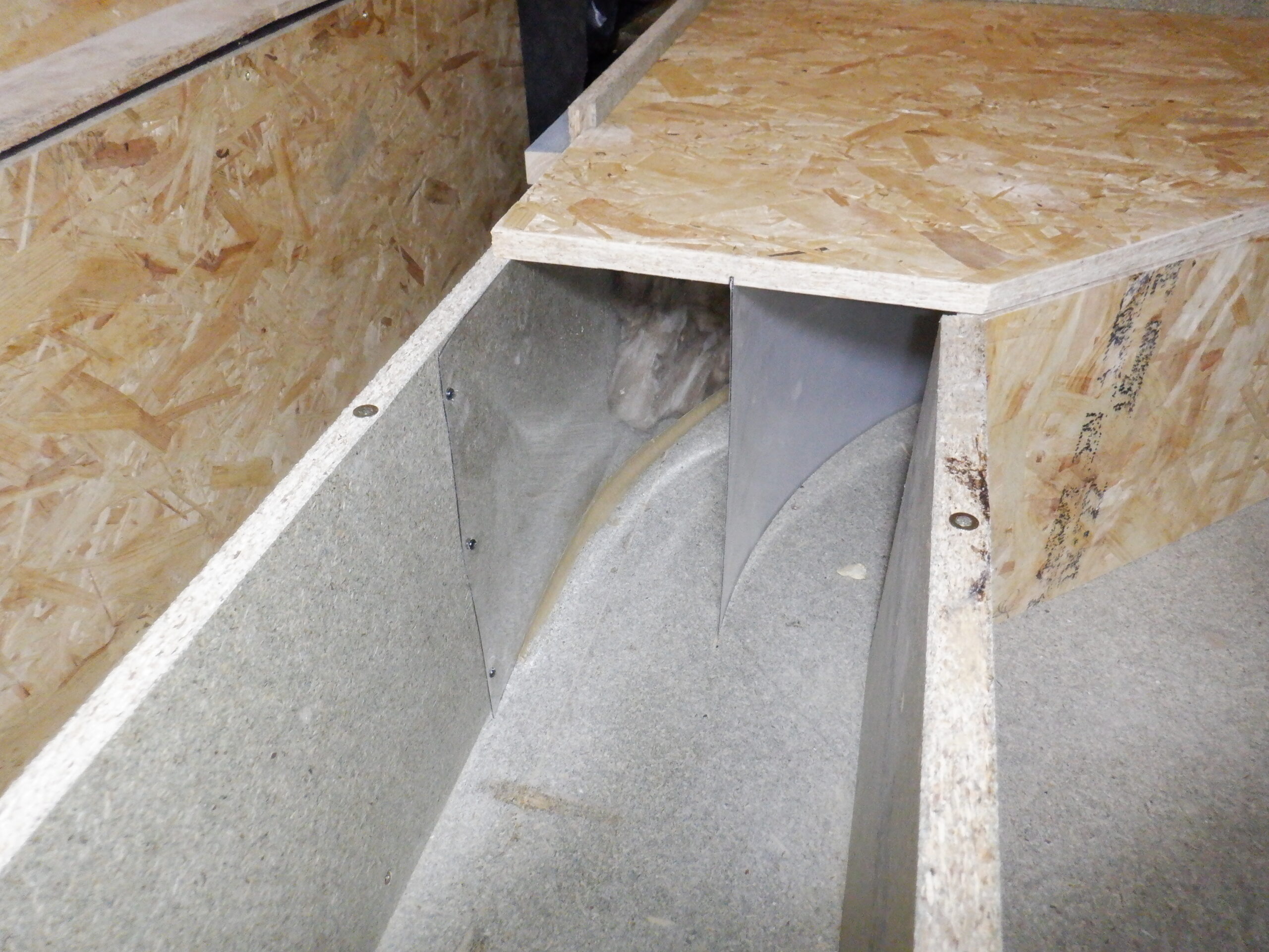
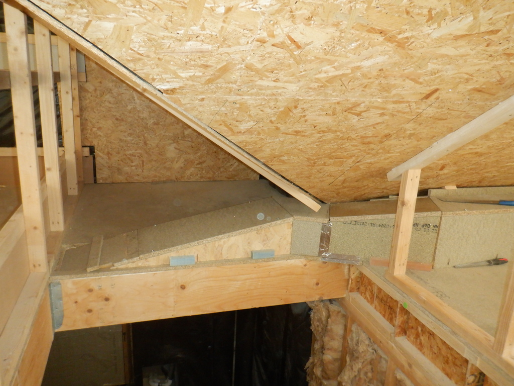
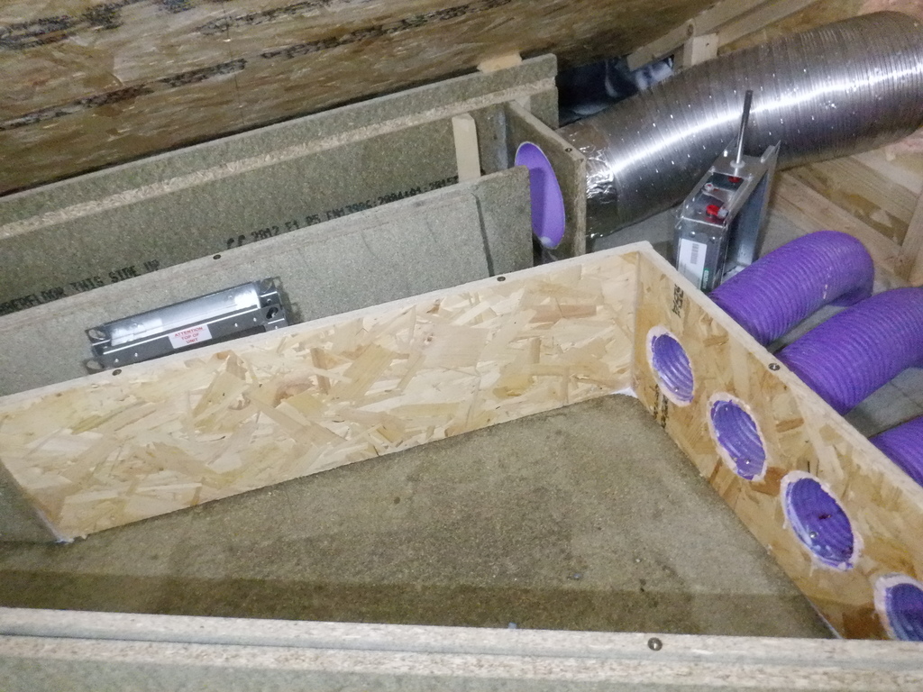
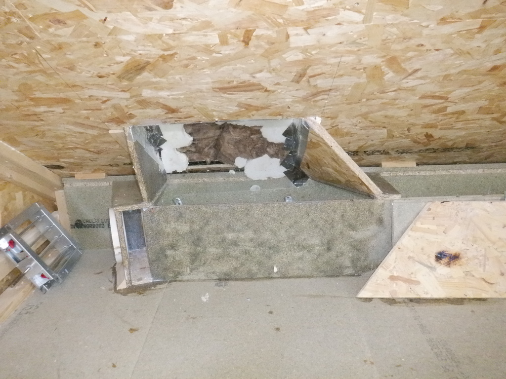
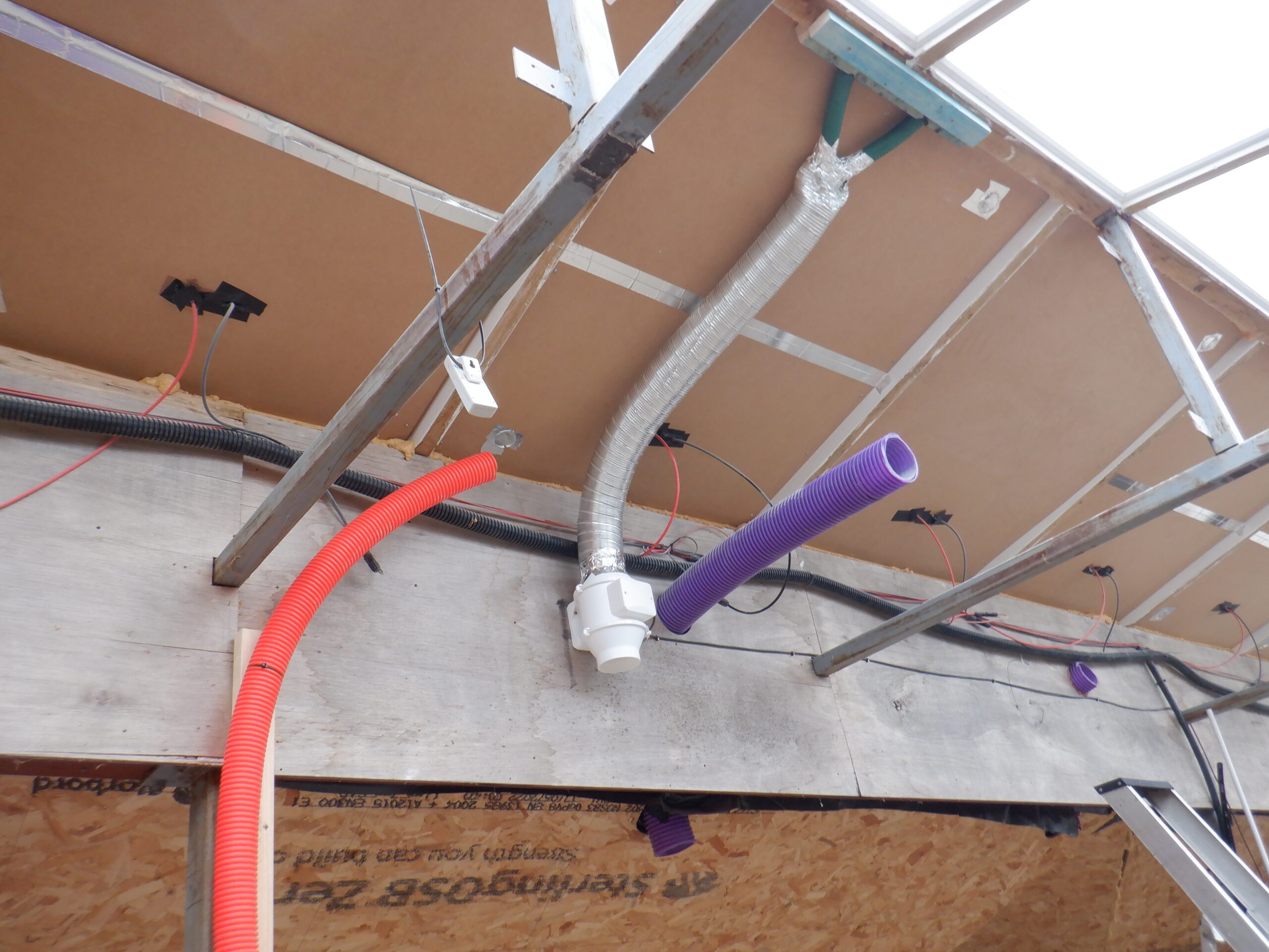
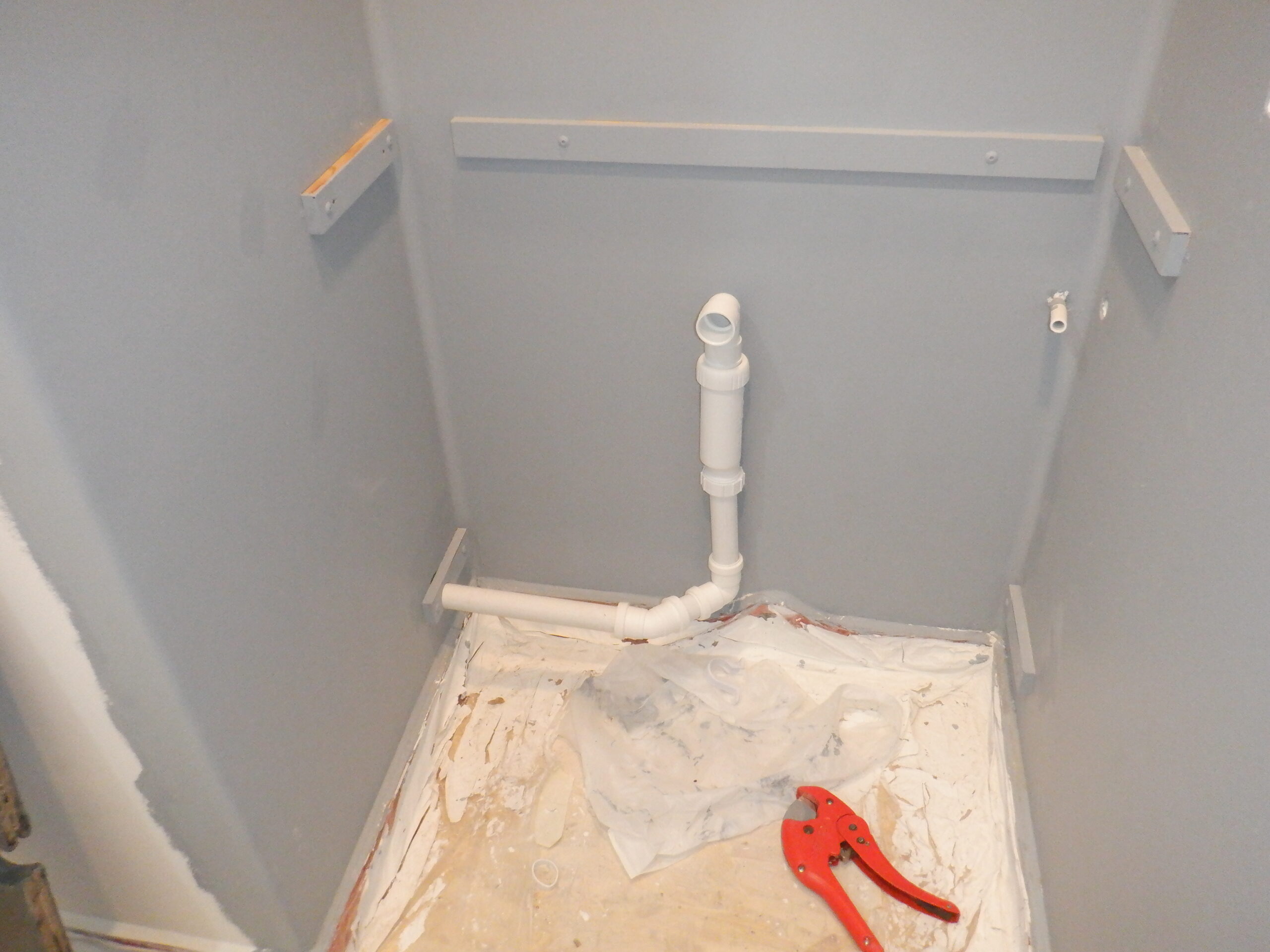
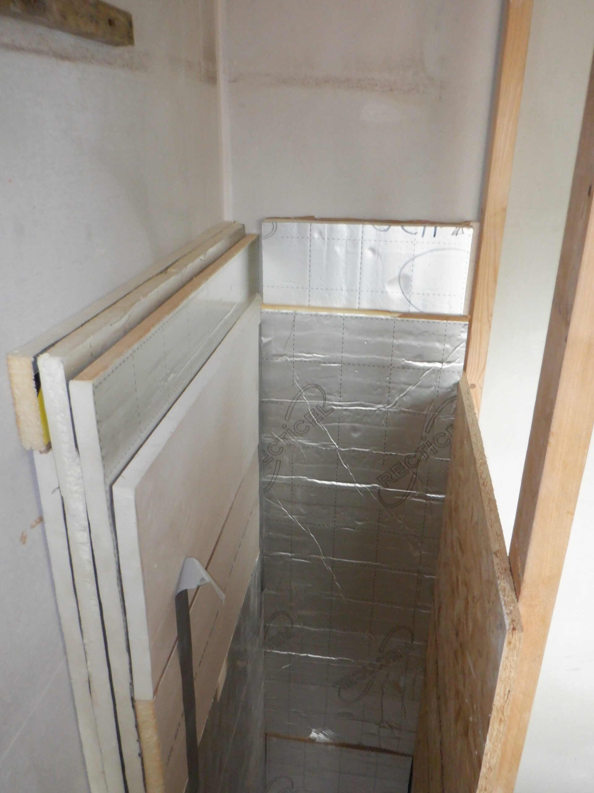
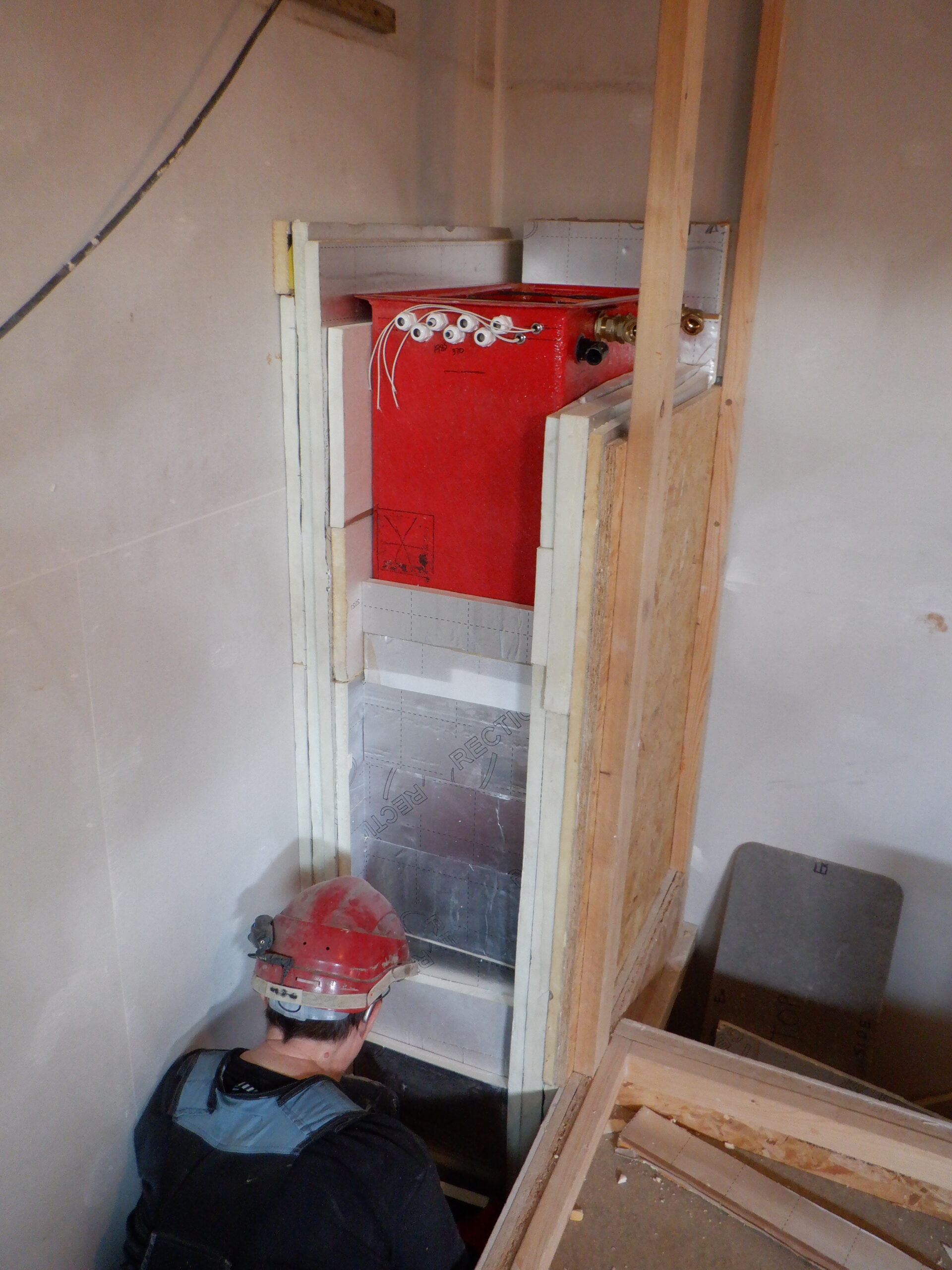
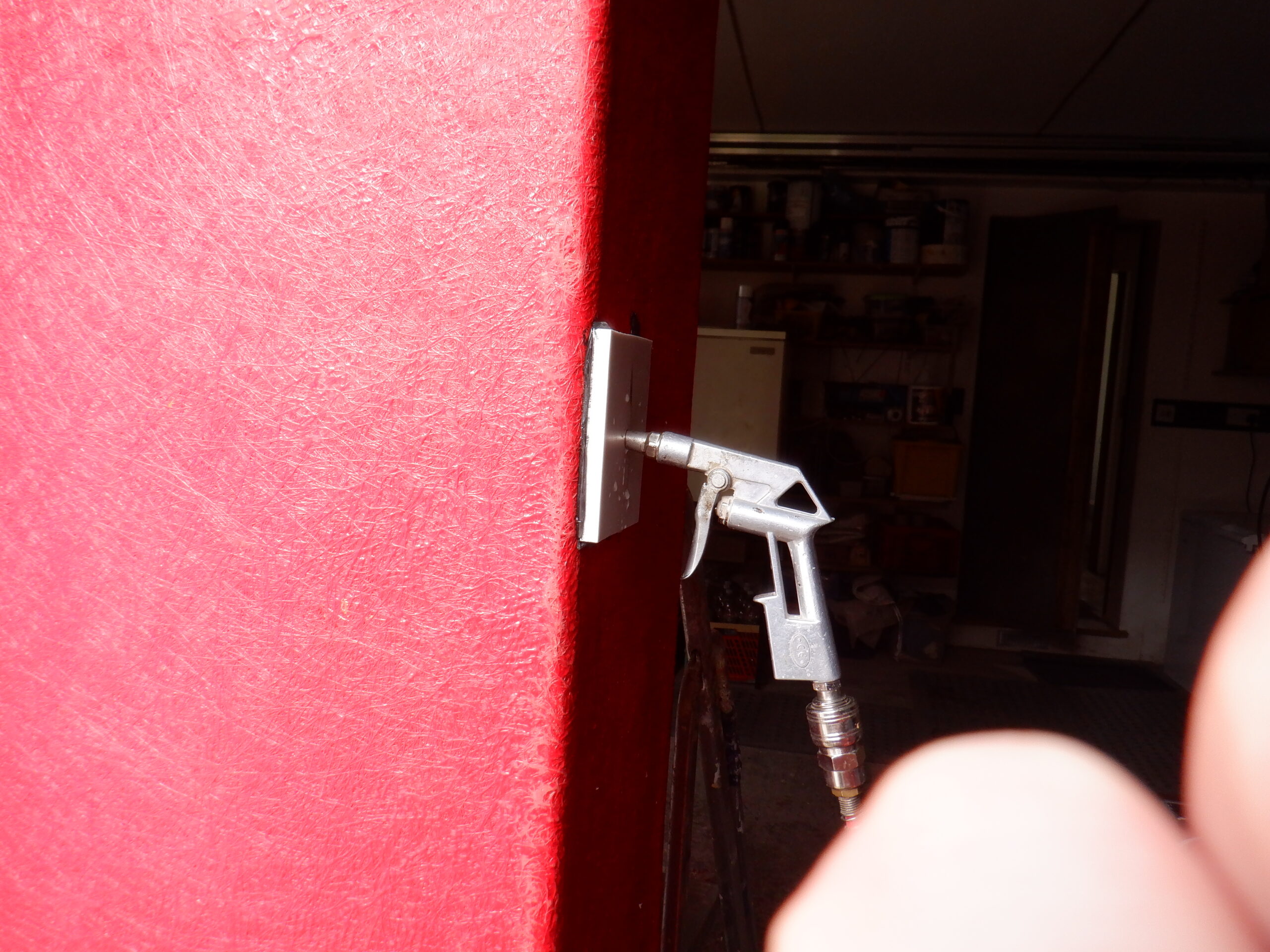
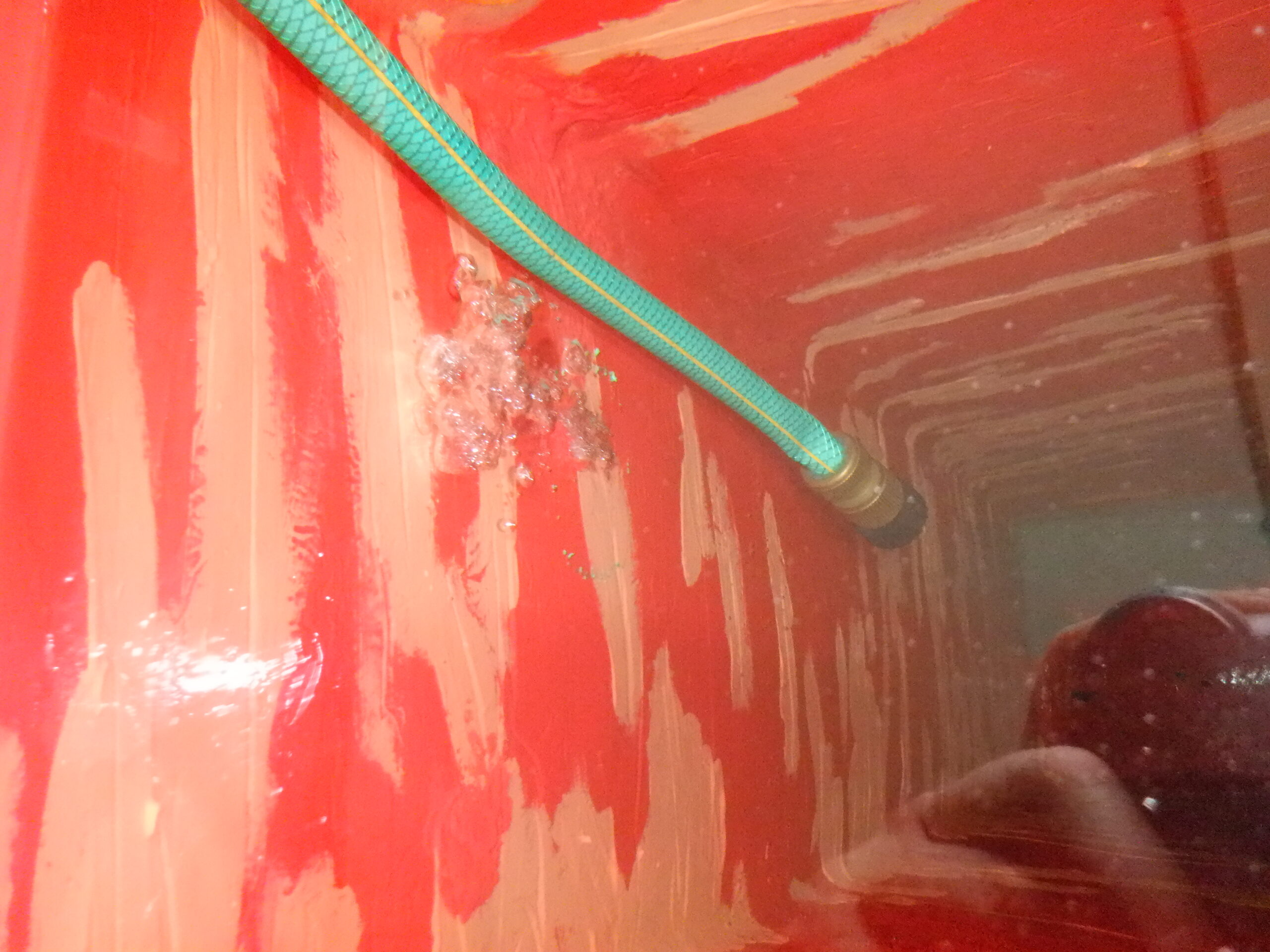
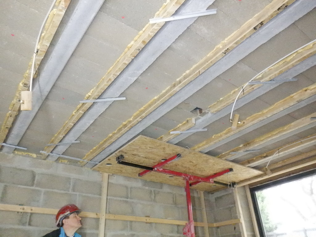
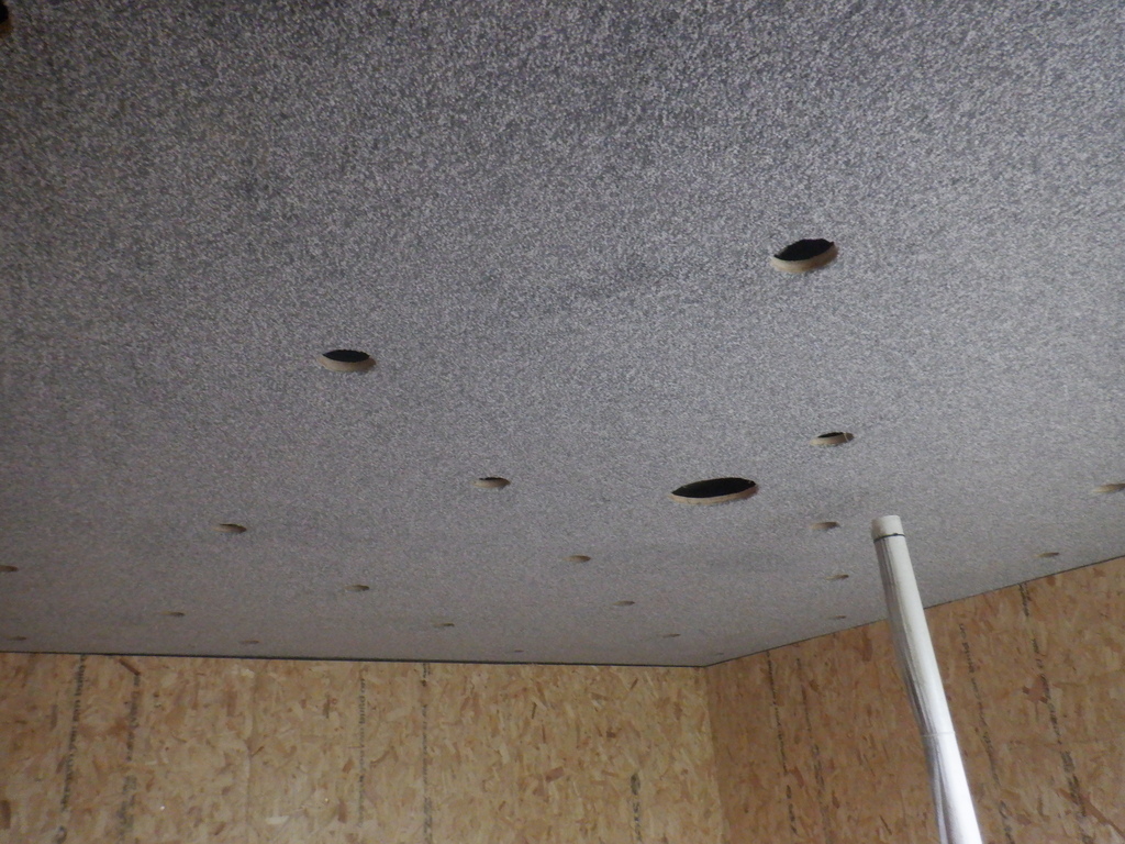
We did four sets of seven lighting units, plus half a set of just four units in the last odd row, finishing off the ceiling. There are a total of thirty-two concealed lighting units, each one with a fully controllable white brightness level plus some splash of colour too.The next job was to install our fire suppression system up into the ceiling space as well. We already had a 15mm plastic pipe threaded up through the wall into the ceiling space so we simply just took some 10mm plastic water pipe and threaded that down inside the 15mm pipe (the other end appears under the floorboards out in the hallway) and then put on a couple of T-junctions to split the water supply off into three different directions. One hovering near the window, two feet in. One in the middle and the third one nearer the back of the room. They all have 90degrees bends on them, going into a short piece of copper pipe, this goes through a small chunk of CLS timber and connects to the end cap which will have the spray nozzle fitted later on. We got these wooden blocks done now so we can reach up later on to screw them into place when we are lifting up the ceiling boards up into place. We tested all the joints by pressurising this section with compressed air and squirted washing up liquid around each joint to make sure that there weren’t any bubbles coming out.
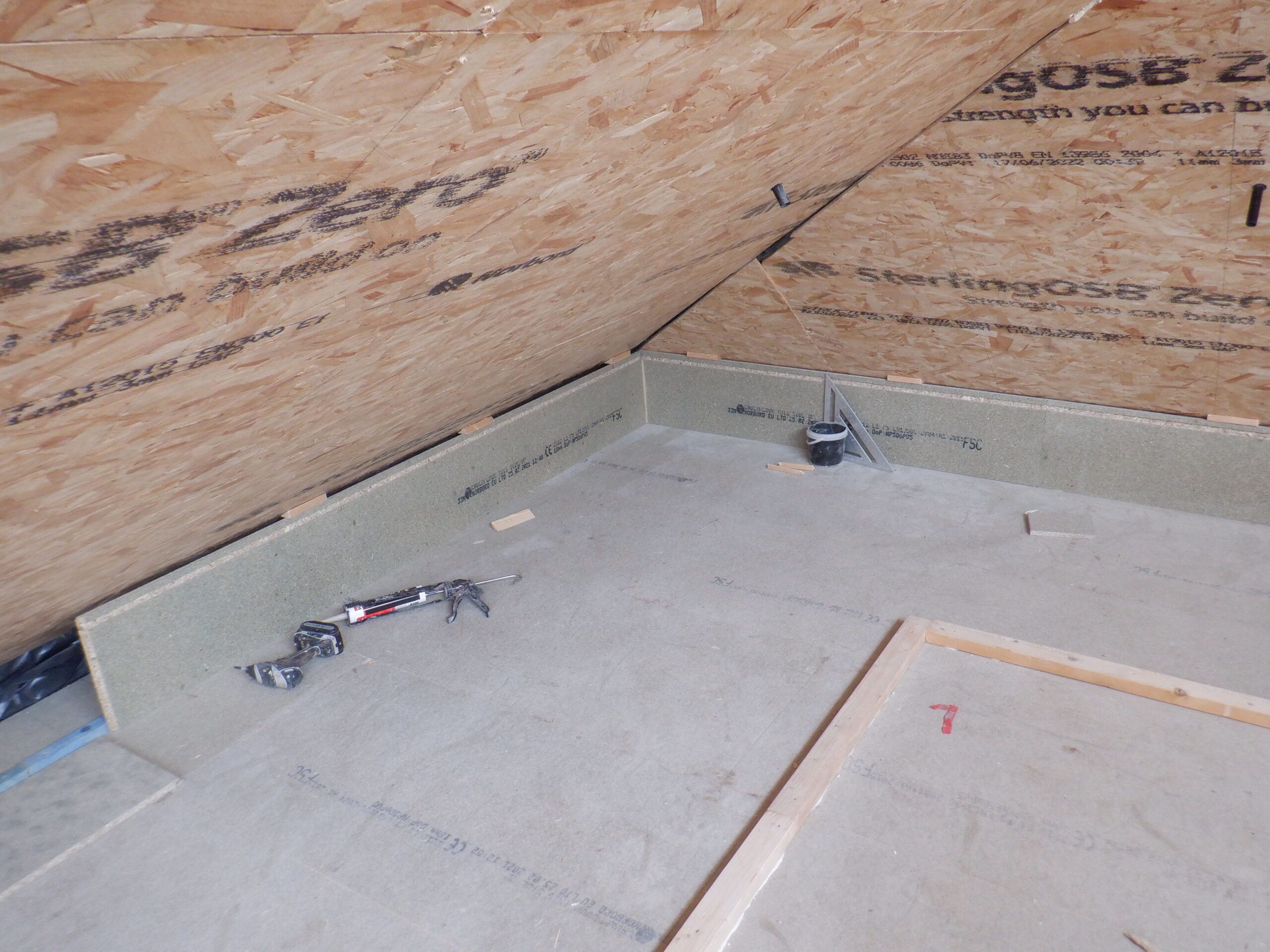
Entertainment room fire supression pipe work
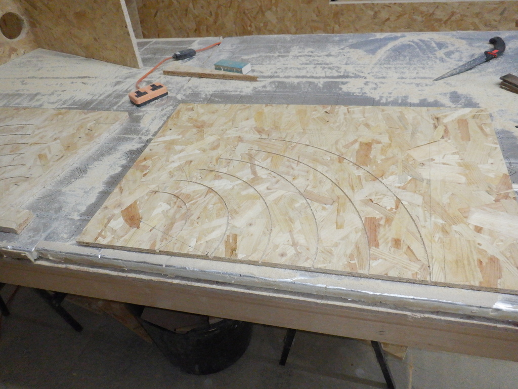
Talking about ceiling boards, that is our next step. We took six sheets of our 18mm OSB boards and laid them out in our Great Room, lifted up off the floor with several full lengths of CLS timber. But, before we did that, we had all six of them stacked them up in a pile, on our work table. We proceeded to cut tongues and grooves in the appropriate edges so that the six sheets will fit together into a single combined ceiling, three boards wide and two boards long in the 8feet direction. The room is basically 12feet wide and just under 16feet long. We assembled them into that pattern on the floor and then tied them together using ratchets and straps to draw the tongue and groove together nice and tight, as if they were fully engaged up on the ceiling.
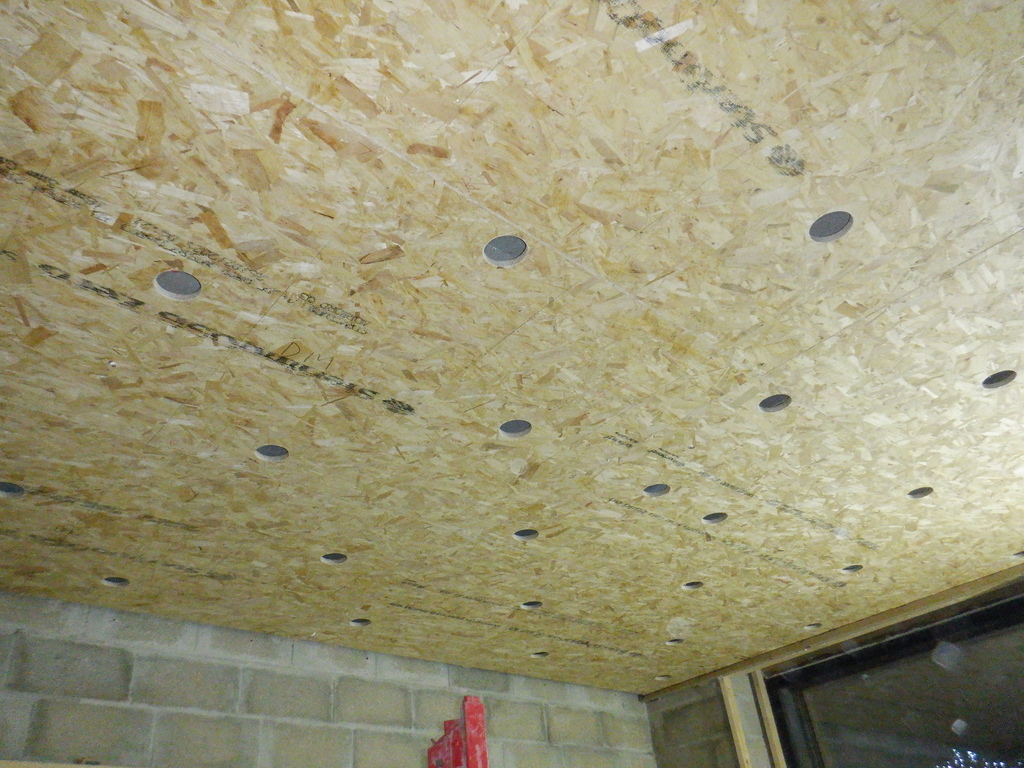
Now we can mark out where we want all the lighting units, plus also the air ventilation port as well onto the boards. We knew that the distance between each of the concrete plus wooden beams is 520mm, and each one occupies approximately 200mm, which means that there is a space of about 300mm that we can lay out and position our lamps. We decided that we would randomly shift each lamp position around a bit so that we do not create a ?boring? grid like pattern. We used our Tungsten carbide tipped core cutter measuring 95mm in diameter, and we made short work on drilling out 33 holes, especially using our mains powered Black & Decker electric drill!!
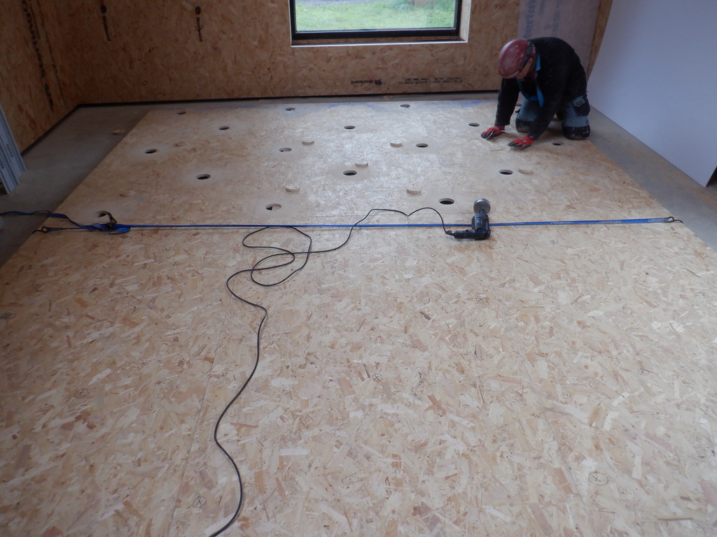
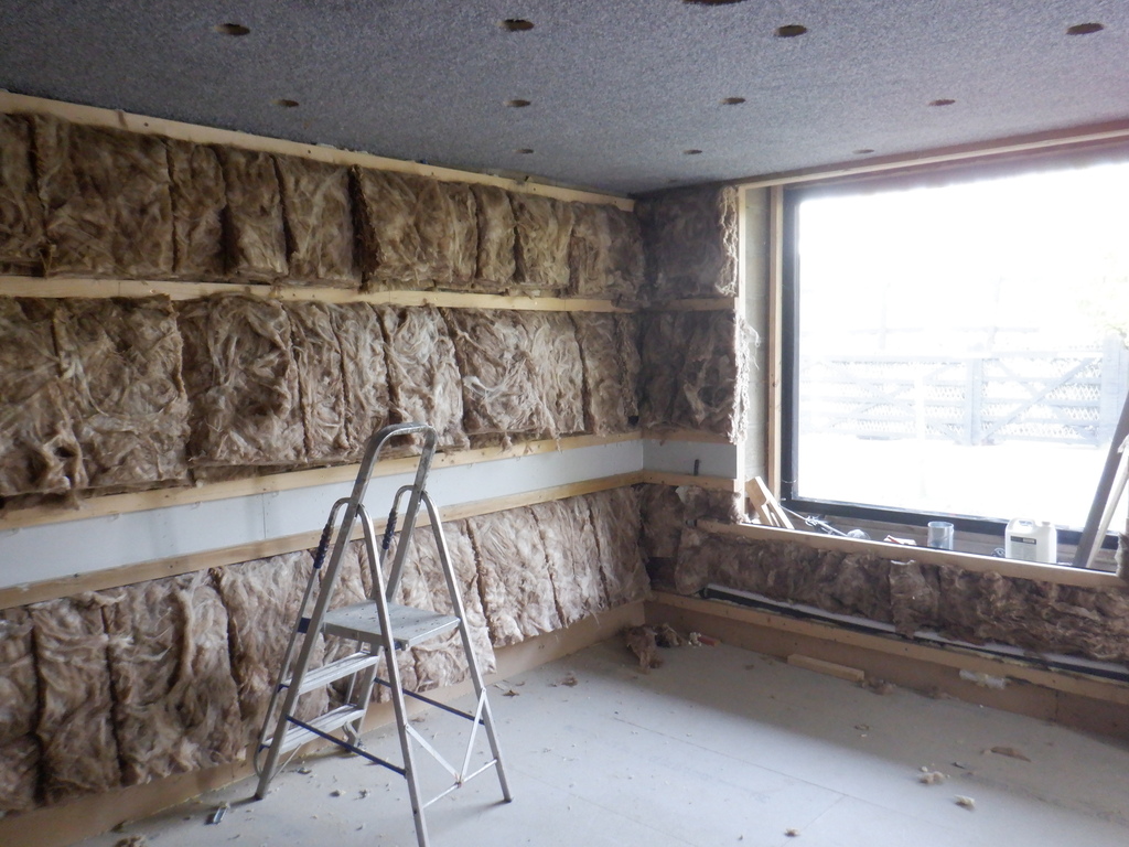
Entertainment room ceiling have light holes cut
We are nearly to mount these six boards up to the wooden beams, but first, we had to unscrew the top horizontal rail off the concrete walls because it is in the way of the OSB boards going up, plus also the carpet we are going to stick up later on. But, we realised that the top rail that is going across the window is completely glued in, and the wooden ceiling beam is hidden behind it, where we needed to screw up the ceiling boards. This meant that we had to chisel away a fair chunk of this top rail, to increase the gap above so that we can slide in our 18mm thick OSB boards plus the 11mm padding layer we have put up on all our wooden beams. What a fuss!! This is what you get when an original idea didn?t quite work out completely correctly. But, We made it.
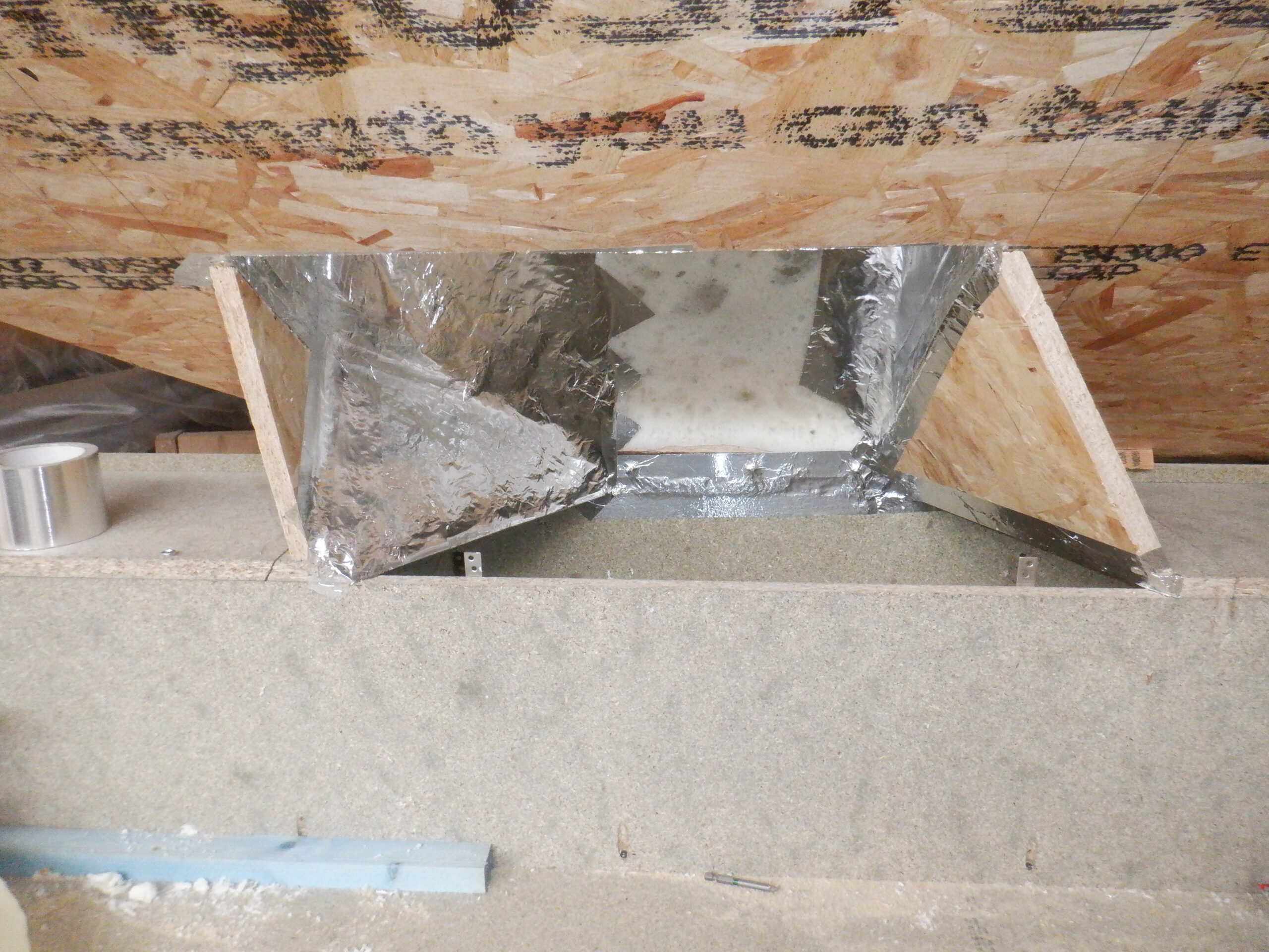
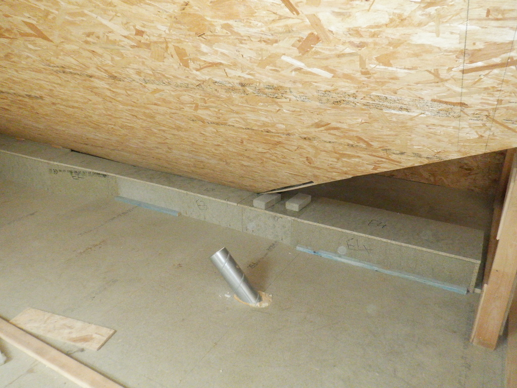
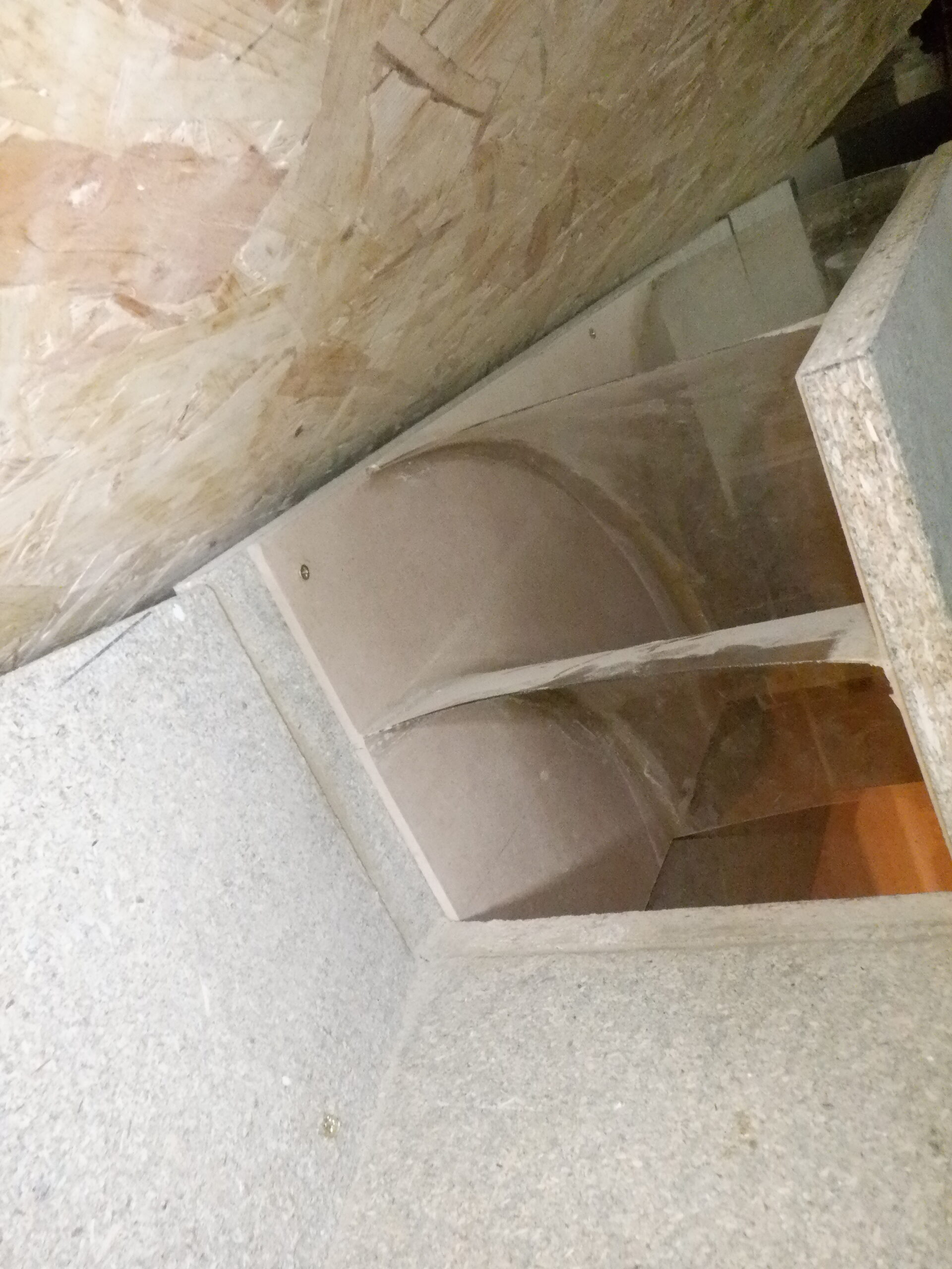
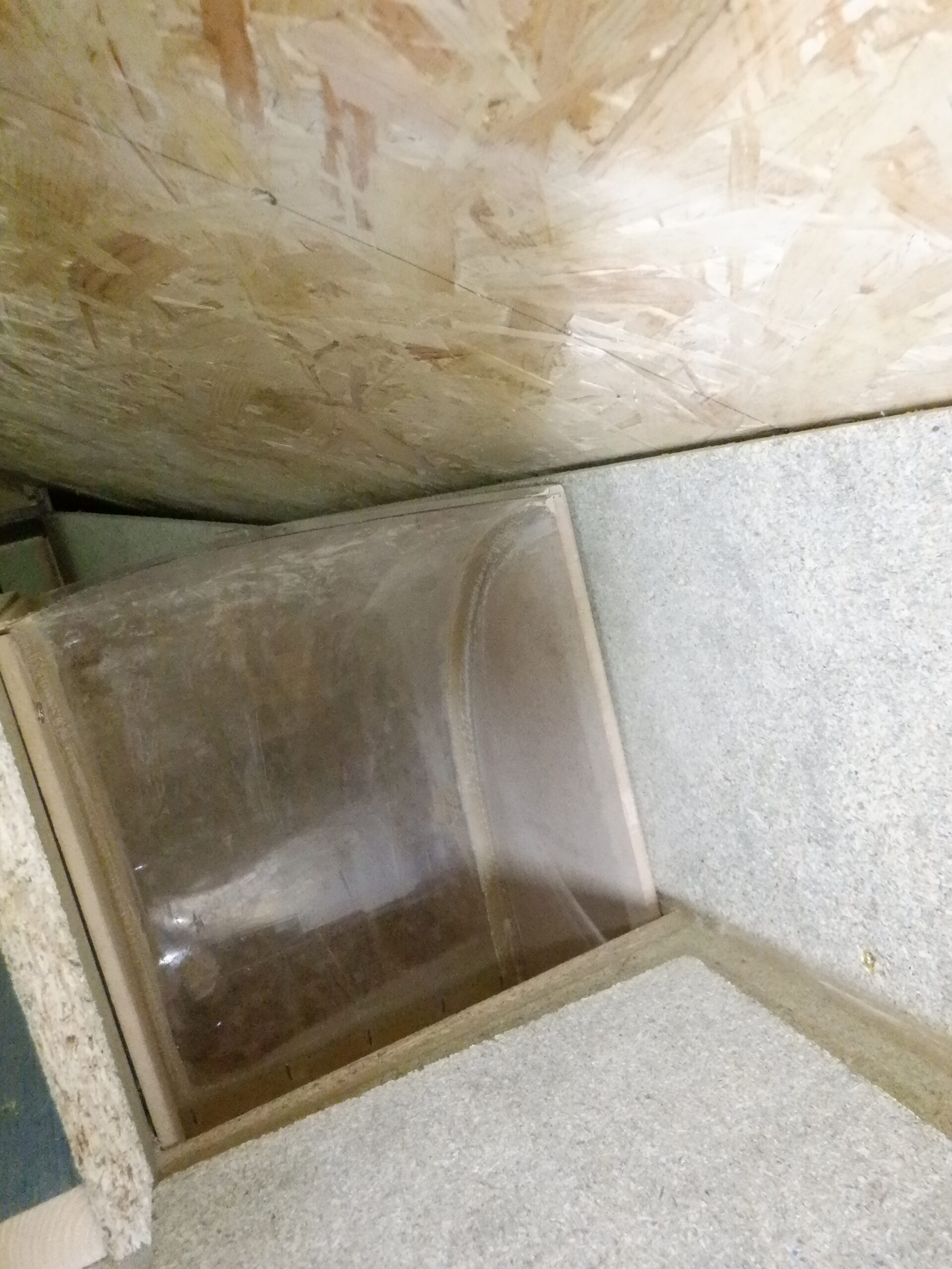
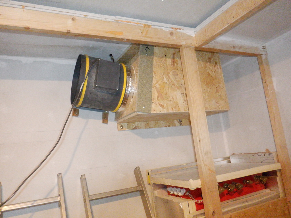
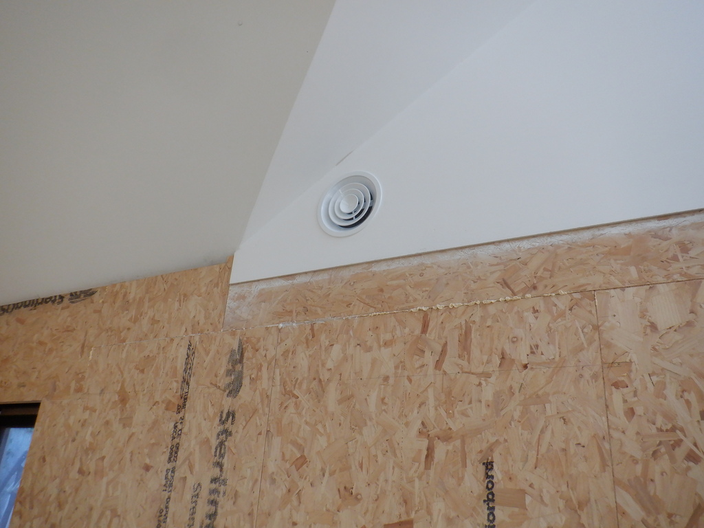
Oh yes, one of the last thing to do while the ceiling is open, is to glue up some pieces of concrete blocks up around the metal air vent pipe that is sticking downwards, ready to be attached to the pretty vent cover. There is a gap between two neighbouring concrete blocks so we needed to fill in that gap with more heavy mass material, to reduce the amount of audio sound waves escaping out of this room. We found some left-over pieces outside in our swimming lane, sliced down to the required dimensions and then glued it up into place using PU Construction glue, and a tall prop to hold the block up while the glue set.
The next job, the big one, of putting up each OSB board up to the wooden beams, screw and glue them into place. We got out our massive board lifter mechanism we bought ten years ago and it effortlessly lifted these 27kg heavy boards up with ease. We carefully aligned the long edge against a set of marks that represented the wall surface and shoved the short end into the gap above the window. It got all glued and screwed in at that point.
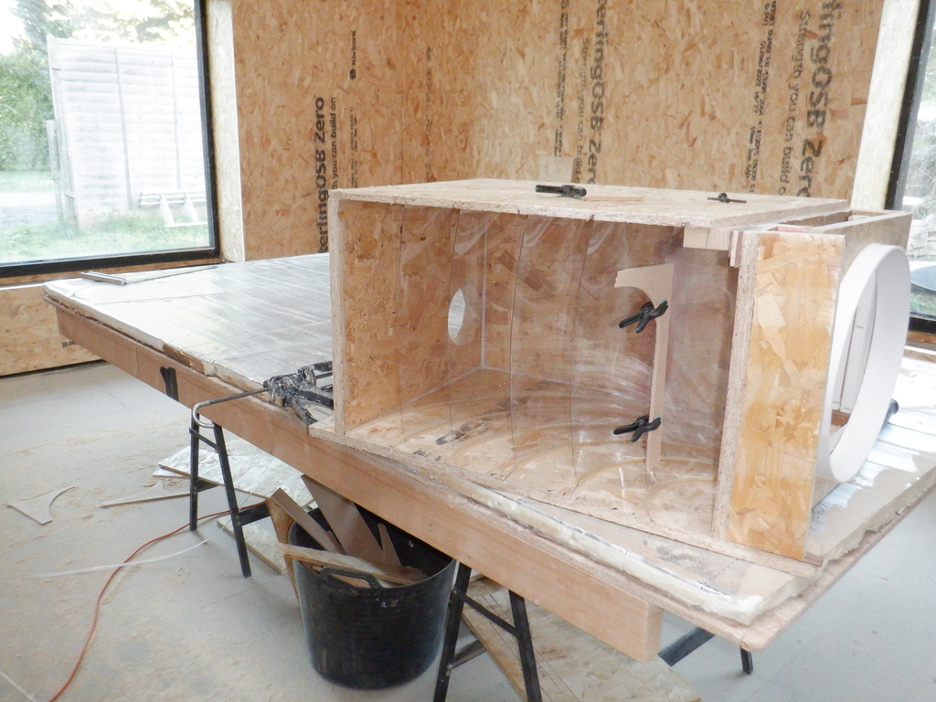
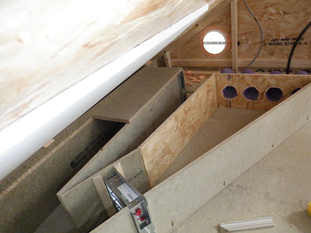
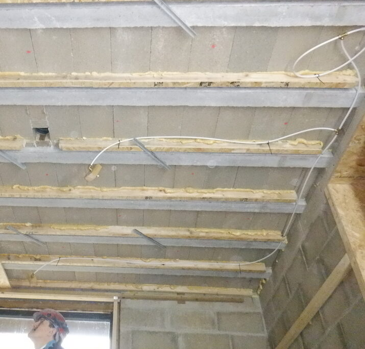
Entertainment room ceiling showing conduits and first board test fitting
We then put up the second board along that line, after slicing off about 120mm off the end. We engaged the tongue and groove joint, made sure that it was very straight and then also glued and screwed that one up too. We repeated this twice more to put up the remaining four sheets. It was jolly hard work but we made it !!
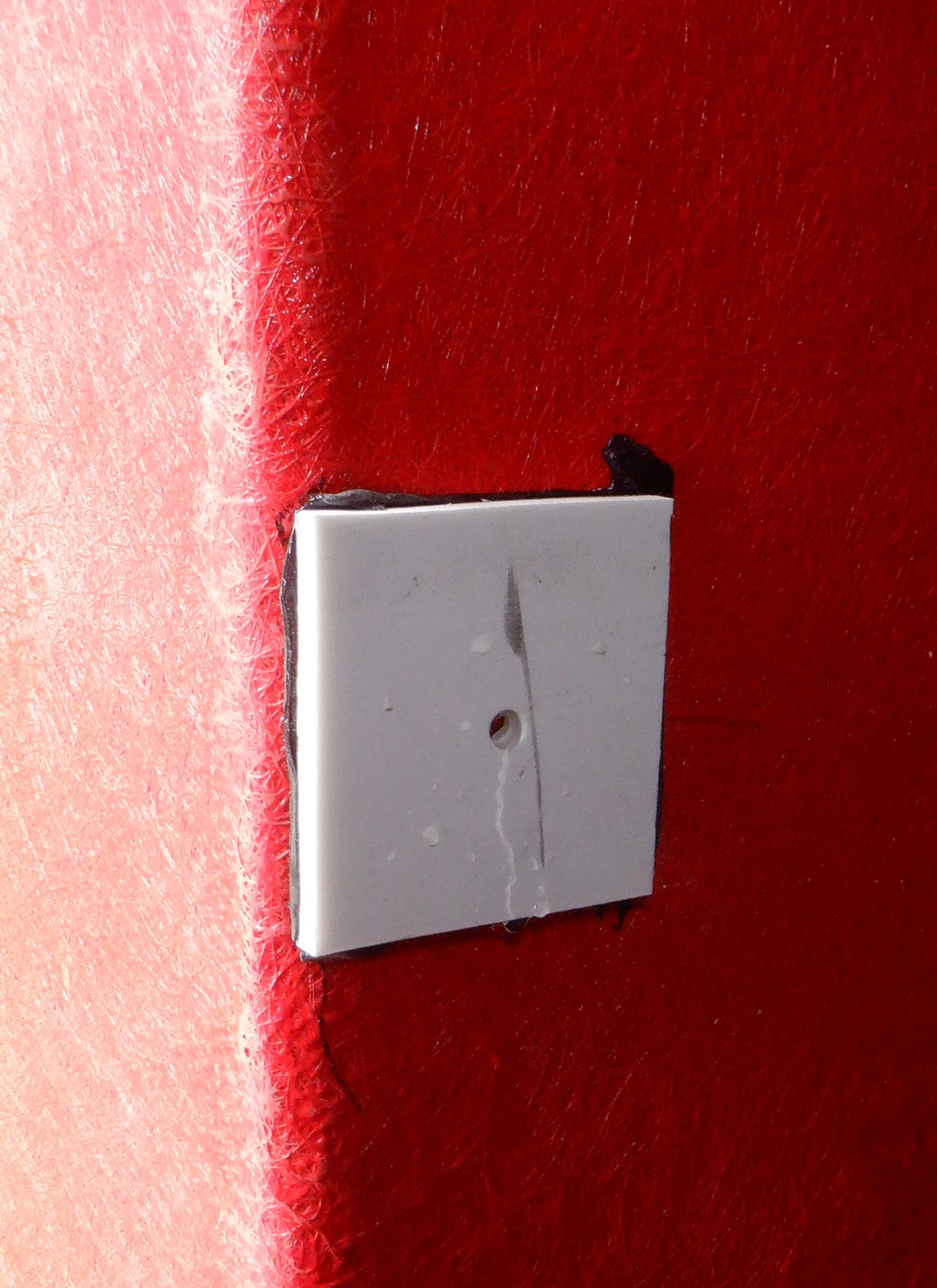
We remembered to drill a small hole to let the fire suppression spray nozzle through and glued liberally the nozzle into place with PU construction so that we could undo the nozzle cap later on. We screwed the wooden blocks to help lock them in tight.
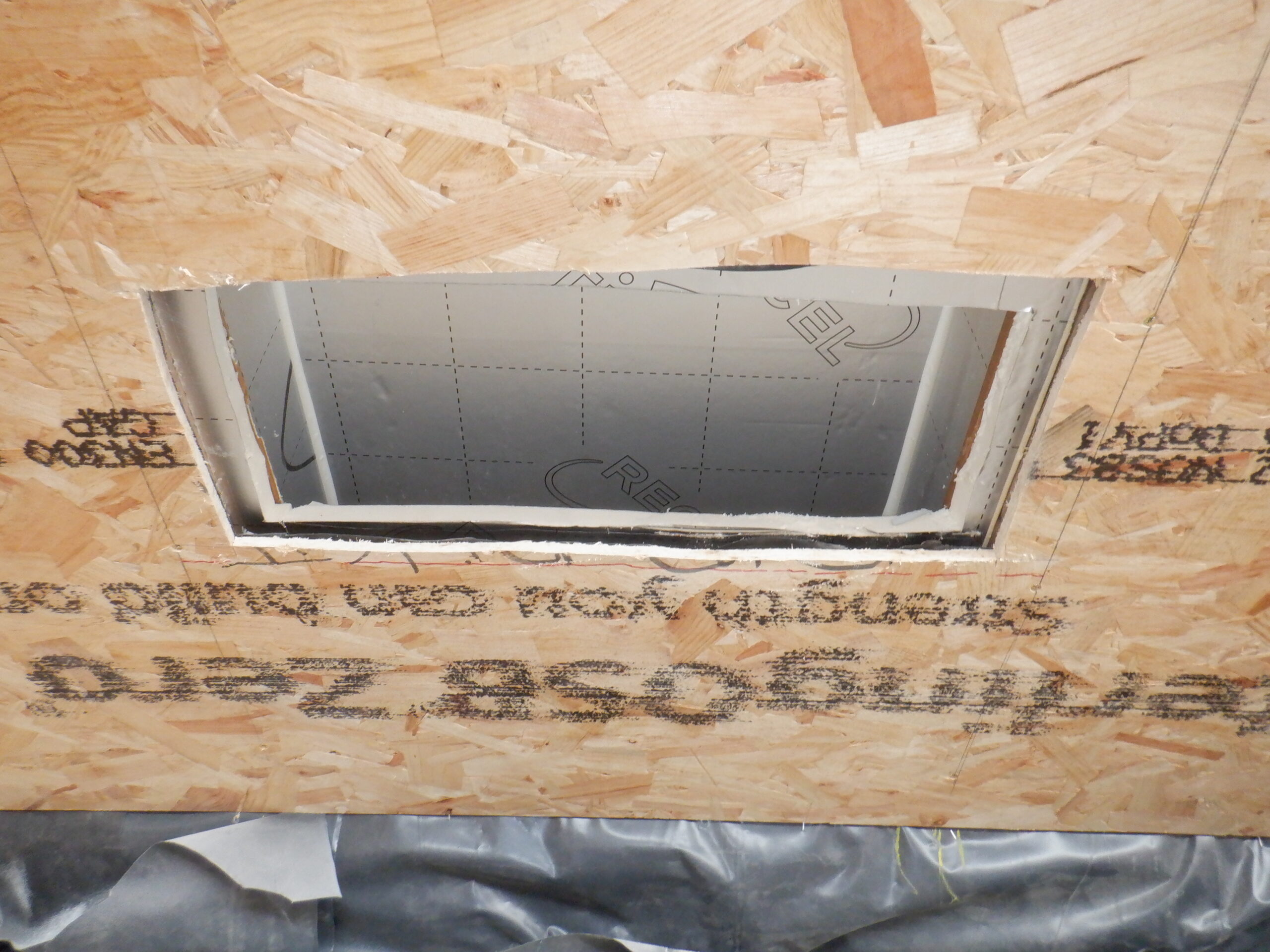
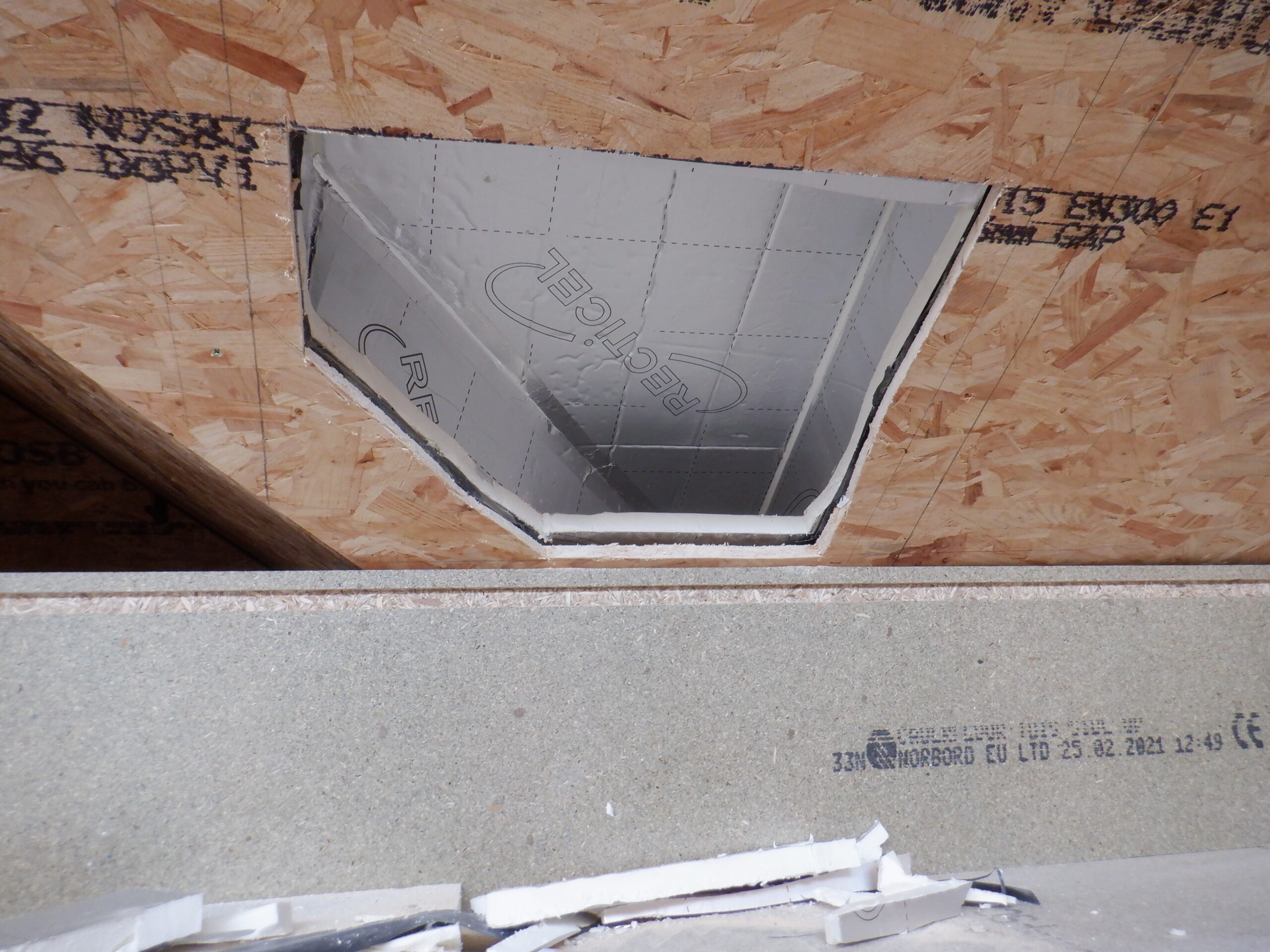
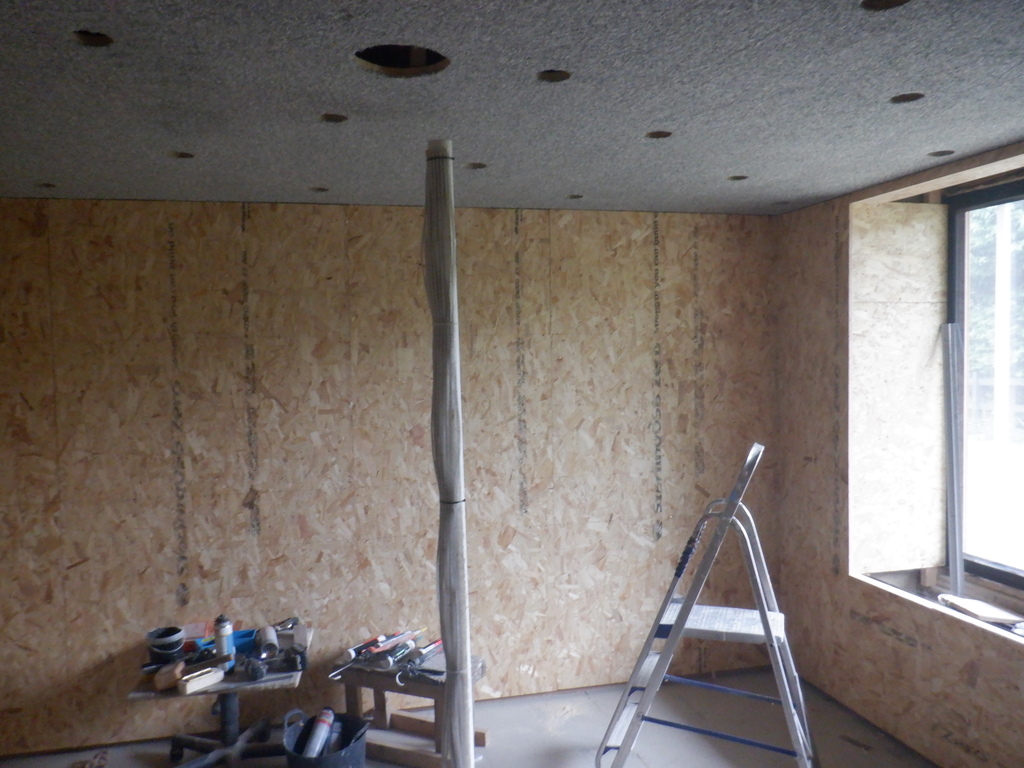
Then other thing we did up on the new ceiling, was to enlarges the ventilation hole. We did only a 95mm hole because we knew that we could be slightly off position and we wanted to see where we managed to get the original position. We were pretty close actually! It just needed a slight shift by 5mm away from the window and we cut out a new 220mm hole, ready to take the ventilation cover.
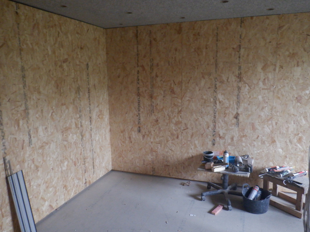
Entertainment room ceiling boarded
Now the next job is to put up the carpet!!
We ordered five pieces of carpets, the cheapest ones we could find and ended up paying well over £350!! We were going for a darker shade of colouring, but our head of the household put her foot down and selected a paler set of colours!! We ordered a 4.8metre by 4metre width for our ceiling, in a steel blue speckled colouring. It has a felt backing. We knew that it will glue just fine because we had previously got free samples and we tried various types of glues, to see which one is practical to use, to see how each one dried and see how strong the bond was afterwards. We tried wallpaper paste, a latex rubber glue and a contact glue. The wallpaper paste completely failed to stick at all, the latex rubber glue took absolutely ages to dry and wasn’t sticky enough to do the job of holding up the carpet while it finished drying. In another test, we did successfully use this latex rubber glue to stick a piece of carpet to the wooden board very well indeed which will be good for the walls. Anyway, we settled on the third type of glue, the contact glue (Evostick), because it dried very quickly within 10 to 15 minutes and we could press the two halves together and proved very strong. We tried ripping the sample carpet off and it started tearing the carpet itself instead of the glue. So we knew what type of glue to use.
Just a quick note about the cost of the carpet mentioned above. Yes, it is an extra cost to our overall build, but actually, it is not that high an extra, because we saved money by not having to put up our high precision plasterboards, which would have cost about £250 (13 sheets worth) so the extra on top is only £100 .. We Can Live With That!
The next trick we had to perform, is to get this twenty square metre carpet up onto the ceiling, upside down! We built a tall mobile wall with a shelf to hold the excess carpet in a fanfold arrangement. We needed a flat vertical surface so that the carpet’s backside is laid out flat, ready for the contact glue to be painted on. This flat surface is almost the entire width of the room (3.6metres – 12feet) and we decided not to paint to the very edge because the carpet is still at its original 4metres width and it needed extra room to ‘flop’ down.
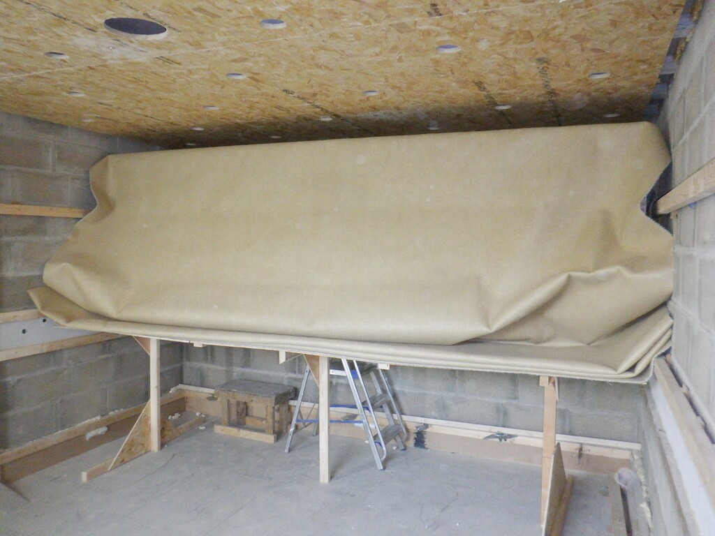
Ready to hang ceiling carpet folded up waiting
In order to make sure that the very first attempt of pushing up the first edge of carpet goes on flat and without any wrinkles or ruts, we stapled on a 3.6metre length of 63mm CLS timber to the very edge of it, with equal amount of excess carpet left and right. We pulled the carpet up and draped it over our mobile wall so we had about 1metre dangling down. The mobile wall was then shifted so that it was about a 1metre from the end wall (furthest from the window). Once we have painted a strip about 900mm wide on the back side of the carpet, and a similar width up on the wooden ceiling with the contact glue, allowing it to become tact-free, we could lift up the CLS timber above our head while we stood on a ladder and a foot stool. We deliberately positioned the CLS plank against the surface of the concrete wall, sliding it up against it. We had previously marked the concrete wall near the ceiling so we knew where to position the plank so we arrived at the ceiling with the carpet and press hard upwards to get the two glue surfaces to bond together. Now, using a second similar plank but a bit shorter so we didn’t jam up too badly on the side walls, we used this piece of timber to press the carpet upwards continuously, bit by bit, moving further and further away from the completed section.
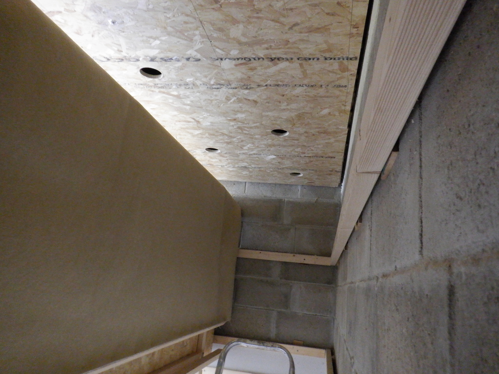
Ready to hang ceiling carpet first strip
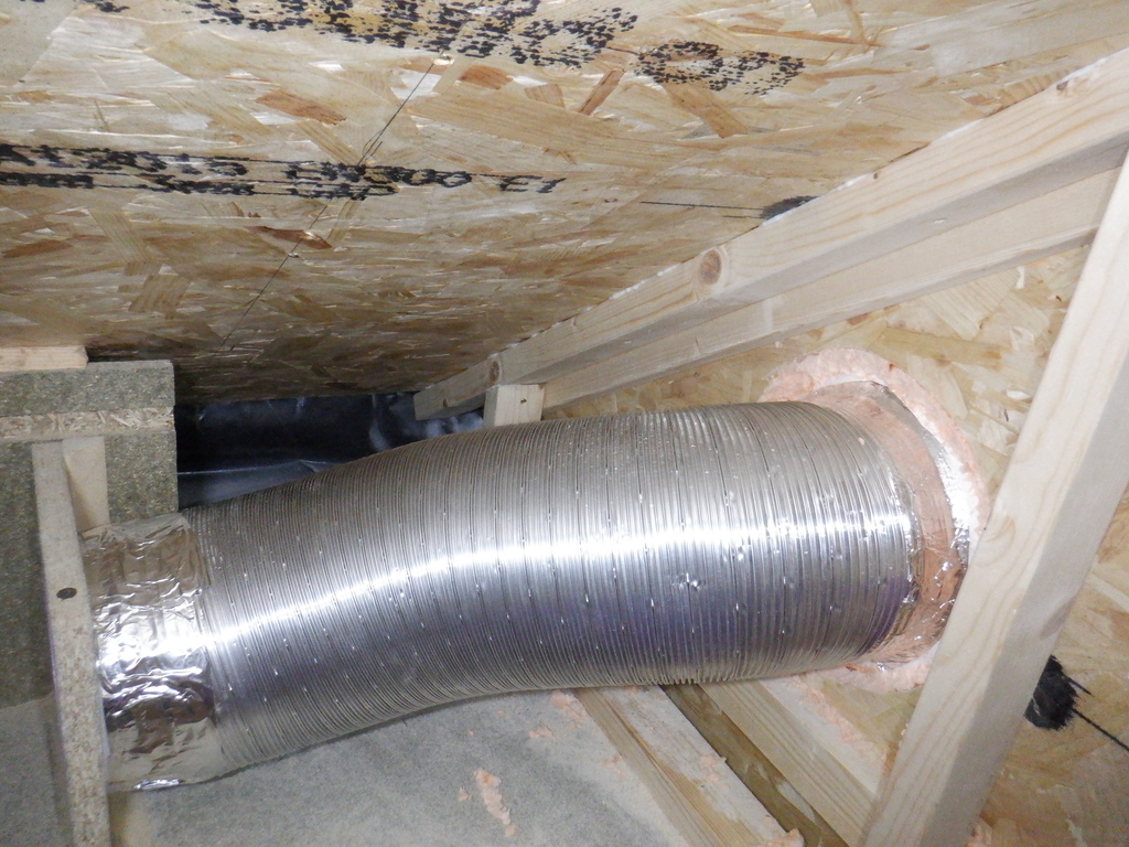
One aspect of this task of putting up all this contact glue, is the very strong chemical solvent smell coming off all the painted surfaces. So, we had to bring in a giant fan to stuck out as much of the fumes as possible. Also, we connected up our 6inch fan to the purple 100mm pipe out in the hallway, underneath the floorboards, and blow in fresh air via the ventilation outlets (four of them) we got in the room. Plus also, we opened the front door and the side door to allow clean fresh air into the house too. We even turned on our main ventilation fan we had previously installed and got it to stir the air around the entire house.
Now, we could duck under our mobile wall, and paint the next section, another 900mm strip, on the carpet and again the ceiling as well, wait for it to tack-free and then move our mobile wall along that 900mm. It was a wiggle, keeping the carpet straight and flat but we got there. then, we then ducked back under to the other side and picked up our rolling CLS timber, to continue pressing the carpet along bit by bit until all the glued strip is done.
We repeated this process another three times and arrived at the window. We discovered that the supplier had given us another 500mm of carpet because it turned out to be the end of their roll so they just gave us the excess for free? very nice of them!!
We had to prop up the last bit of carpet with three extending legs because the weight of that excess carpet was heavy enough to make it not stick up on the glue properly.
We then dismantled our mobile wall, and then went around trimming all the excess carpet off the edges. After that, it was the case of finding all the round holes, all 33 of them, and cut out the carpets, one by one. Oh yes, we also located the three water spray nozzle points and carefully cut around the little metal plate.
And then, finally, we went around the edges of the ceiling, to apply glue to the dangling bit of the carpets and stick that up to get it all finished.
Ceiling carpet glued up
We then remounted the top horizontal rail back up on the wall, making sure that the rail was levelled with the lower rails, by using our six foot long spirit level. We had to drill new holes into the concrete and adjusting the piles of wooden shims, to secure the rail dead flat.
The next job, before we put up the wall boards, is to insert the little plastic hanging hooks up inside the Utility Channel, every 12inches or so, right around the whole room. These hooks will hold up the high voltage mains cabling so that we can supply the old AC electricity to a socket if we need some equipment to be powered by AC power instead of our 50V electricity from our solar or batteries. Plus also, we inserted a length of 20mm white plastic conduit pipe going from the Utility Channel in the far corner furthest away from the window, and threaded the pipe up behind the other horizontal rails, and with a 90degree bend, poked the top end up inside the ceiling space towards the first lighting unit hole. We now can reach in with a hand and grab the cables that will come up from the Utility Channel, to supply power and network connections to our lamps.
Now it is time to insert the sound deadening material in between the wooden rails, plus also to spray PU foam behind each rail plus also the Utility Channel too. We pulled out rolls of our 100mm thick glass wool and cut lengths off, folded them over and stapled them in each gap, hanging down. The space we needed to fill is about 50mm thick, sometimes as much as 100mm in some areas so we realised that putting up double layered of the wool, will bulge out a great deal. This is what we were looking for, in order to increase the density of the glass wool, to help absorb the sound vibrations.
Overfilled with insulation (1)
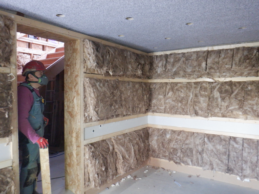
Overfilled with insulation (2)
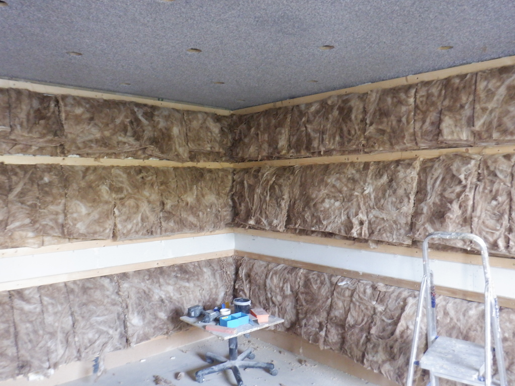
Overfilled with insulation (3)
Now it is the turn of the 18mm OSB boards, to be glued and screwed up onto the rails. We decided that we would not employ our normal step of cutting tongue and groove in the vertical edges, to lock the boards together, to make a smooth surface. This made it very much easier to put up each board, especially considering the swollen glass wool all over the wall! We did glue each joint with our PU construction glue so it was locked together after all. But, we did notice that the joint isn’t as smooth as we normally get. We will solve that problem by sanding the joints with our belt sander and then the carpet will go over it, which will hide all these tiny bits of imperfections!! We went around our walls, putting up three sheets on the side wall, then almost four sheets along the long wall, went around the window and finally, two whole sheets on either sides of the doorway, plus a couple of shorter ones to go up and over the door hole. We wanted extra bits around the door because we needed to sliced into the edge with a 15degree angle, in order to remove a chunk of the OSB edges, to replace it with a strip of solid Oak timber instead. We knew that we are going to be hanging a very heavy dense door and we needed to make sure that the hinges will stay put when screwed into the wooden material. We found a plank of Oak in our garden shed (measuring 95mm wide by 30mm thick and a good 2.4metres long), sliced it in half and sanded all the old weathered surfaces. We glued two strips on both vertical edges of the doorway because we haven’t quite decided on which way around the door will be hung. These Oak strips were glued and screwed into place, including lots of large clamps to ensure the glue joint is squashed as tight as possible.
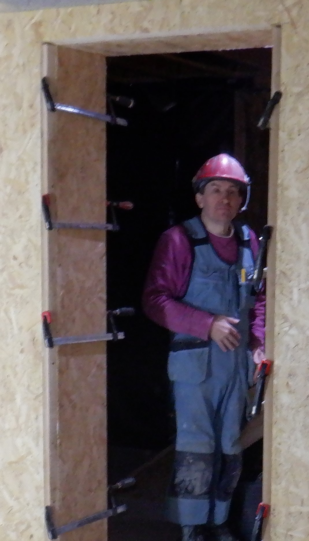
Oak strip clamped on
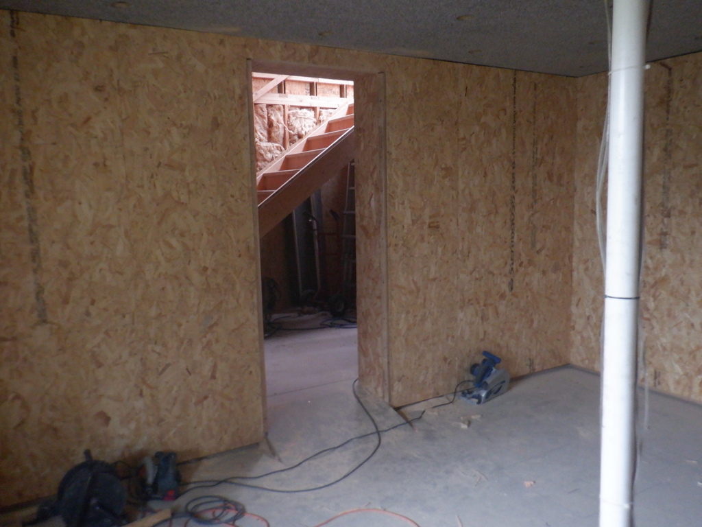
Entertainment wall OSB installed (1)
Entertainment wall OSB installed (2)
Entertainment wall OSB installed (3)
We finished off the week of work, well actually, finished off a whole year of work, by enclosing the window’s alcove with 11mm OSB boards, to hide the last parts of the concrete blocks. The two vertical sides got covered up from front to back, touching the window frame itself. And we put half a piece up on the top surface including several pieces of 1mm thick steel plates, glued to the backside of the 11mm OSB material. These will serve as magnetic attachment points, to hold up the ?lid? that is covering up the mechanisms for the automated blinds.
And finally, we glued on a narrow strip of 18mm thick OSB board, 45mm wide, to go over the top of the window hole, to bring it up to the same level as the rest of the wall surface.
This concludes the work for this year. But, we haven’t finish by a long shot !