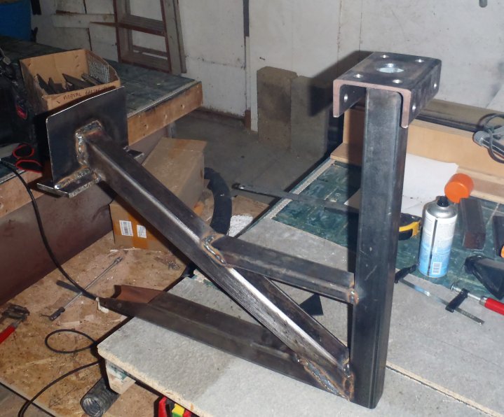
This morning we put together the 3D printed plastic sweep bend and connected it to a length of 38mm diameter black pipe going up the middle of the chimney support arm.
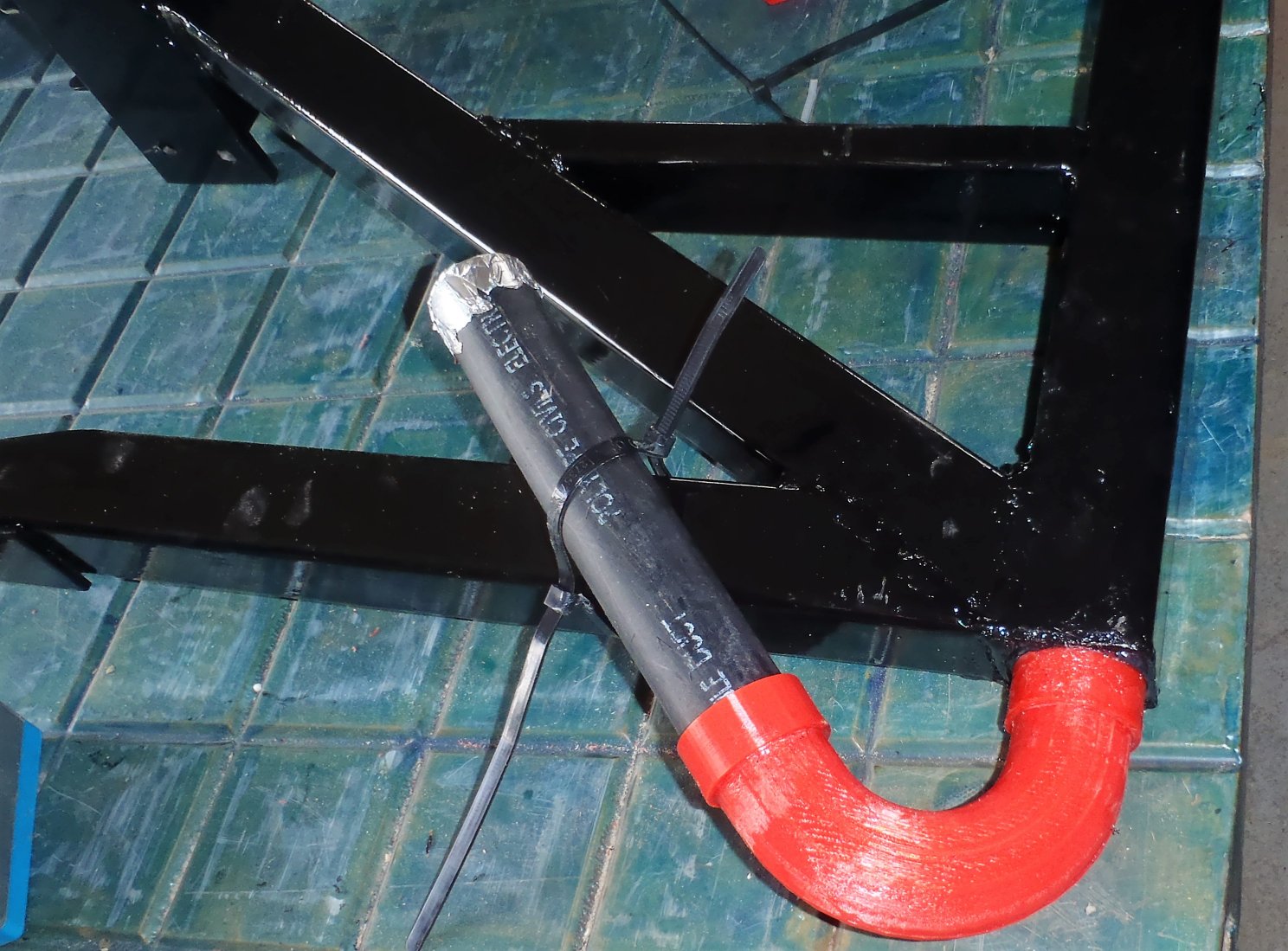
3D-Printed-Bend-on-bracket
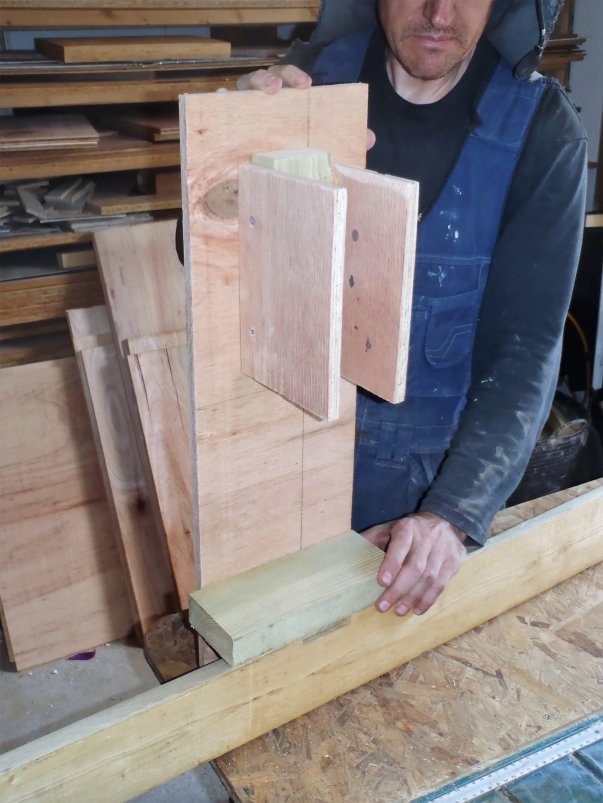
We spent yesterday designing and printing the 135 degrees bend in a tight 100mm radius curve, we had to make it in two pieces with two collars to lock it all together nice and tightly.. it took about 6 hours to print all the pieces. We also printed two little gap filler pieces to go up inside the square steel tube to block off the open ends where we could apply a squirt of silicone sealant and glue the black pipe into place and stop the rain water getting inside the pipe or steelwork.
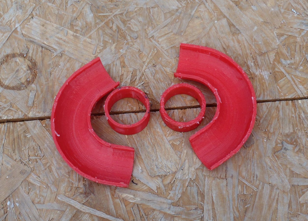
3D-Printed-parts-for-Chimney-conduit-bend
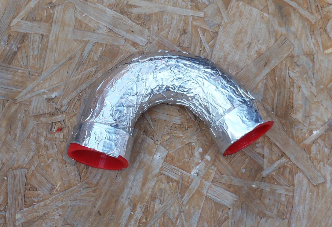
Bend-assembled-and-protected-in-foil-tape
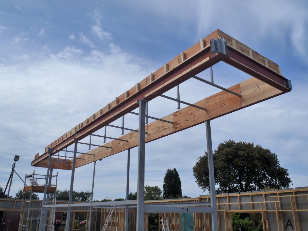
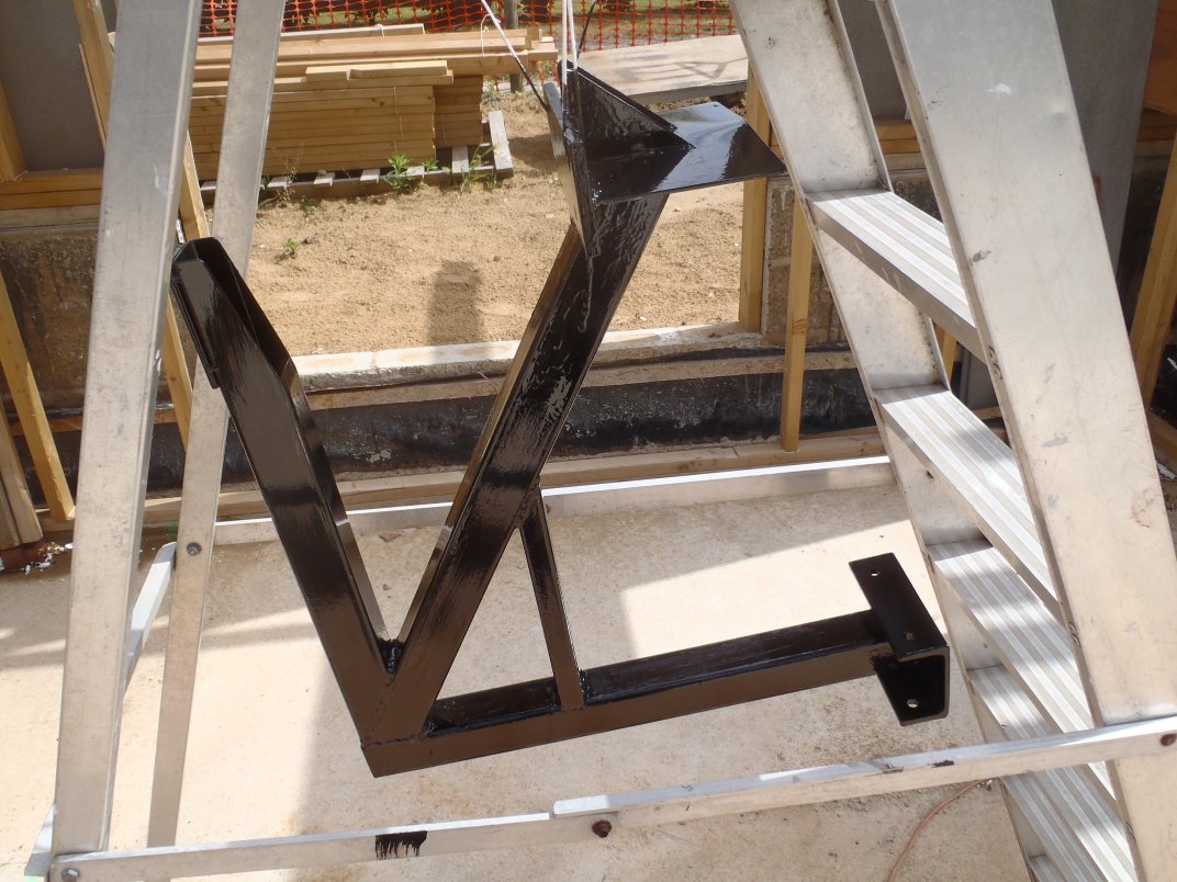
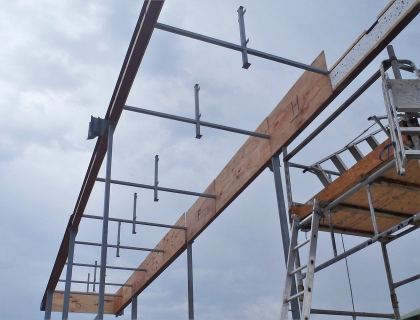
We then mounted the whole thing up on the steel I-Beam with 4 10mm bolts and then drilled a 12mm hole through the bottom flange upwards and into the support arm bracket as well and bolted that section down nice and tight too. The black pipe will eventually extend through the kerb to the inside to allow cables to be connected to the ‘chimney’.
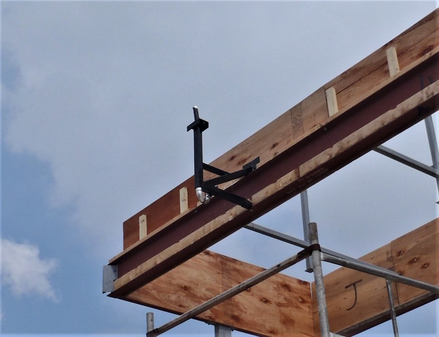
Chimney-bracket-installed
Finally, we put aluminium tape around the new 3D printed (which is made using red PLA plastic) to protect it from the harsh UV radiation from the Sun, while it is exposed to the weather. It will be eventually all covered up by the rafters and roof boards later on.
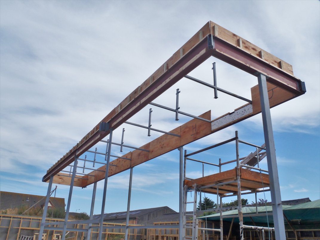
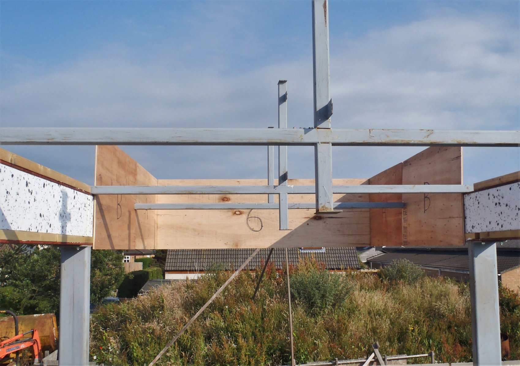
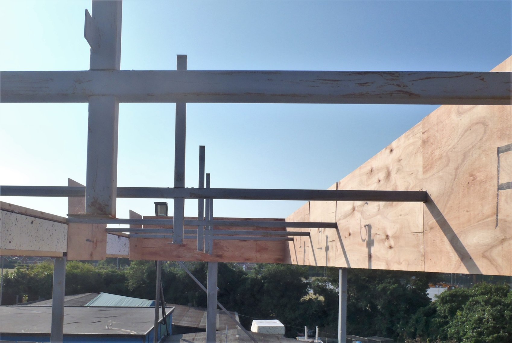
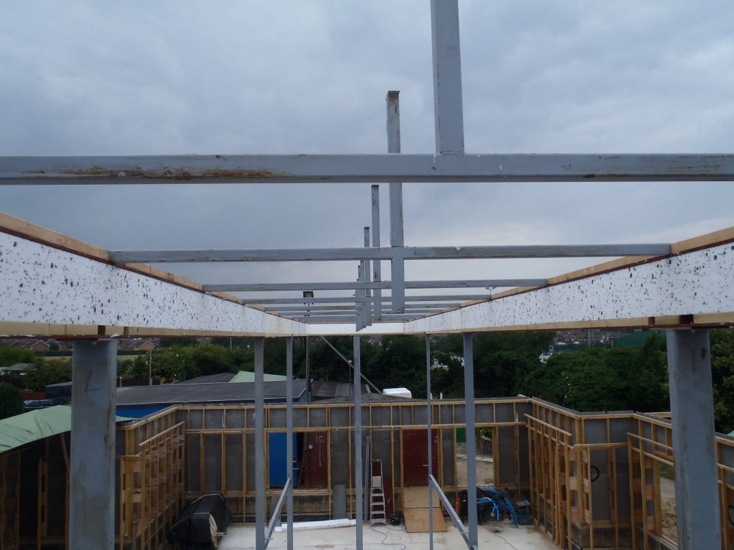
And just before the rain arrived at 1pm, we mounted up the final plywood covering on the inner surface I-Beam to complete the covering of the full loop of the inner Skylight “hole”.