- Overflow
- 28mm High and Low
- 22mm to internal heat exchanger coils
- 15mm Filling
Hot Tank Overflow
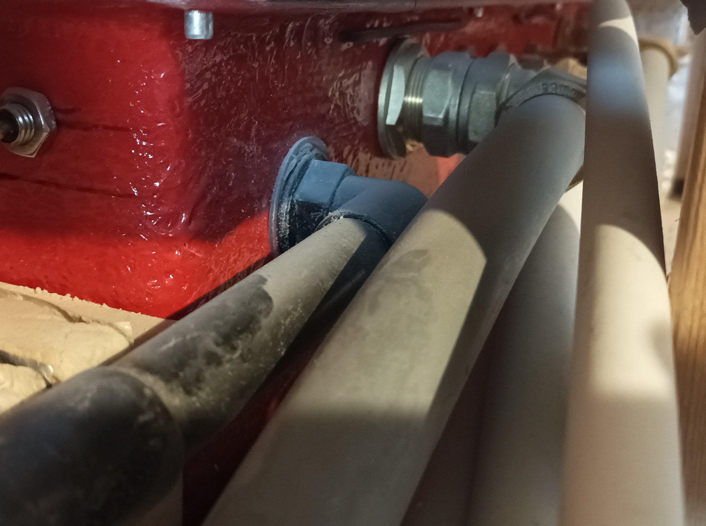
The next connection on the tank is the first of the 22mm to the heat exchanger coils and that came out and also followed around in a gentle curve but diverted back towards the wall once it is across the air duct, ready to be connected to all the Water Management System. We repeated this with another 22mm pipe to connect to the second tank connection. The next point along the side of the tank is the 15mm filling point and again, that came out and also followed the route of the other 22mm pipes, back to the Water Management System. And finally, the last connection, is the second 28mm pipe for extracting hot water and sending it around the house. This pipe came out just like the other ones, and it curved around but, this time, goes slightly backwards so that it can connect to another isolating manually operated valve and a flow rate sensor, before going through a flexible rubber pipe to join to the pump. The other side of the pump then bends around in a tight sweep to go down to the second isolating valve and then connected to the main 28mm circulation system running around the house.
Hot Tank Connections
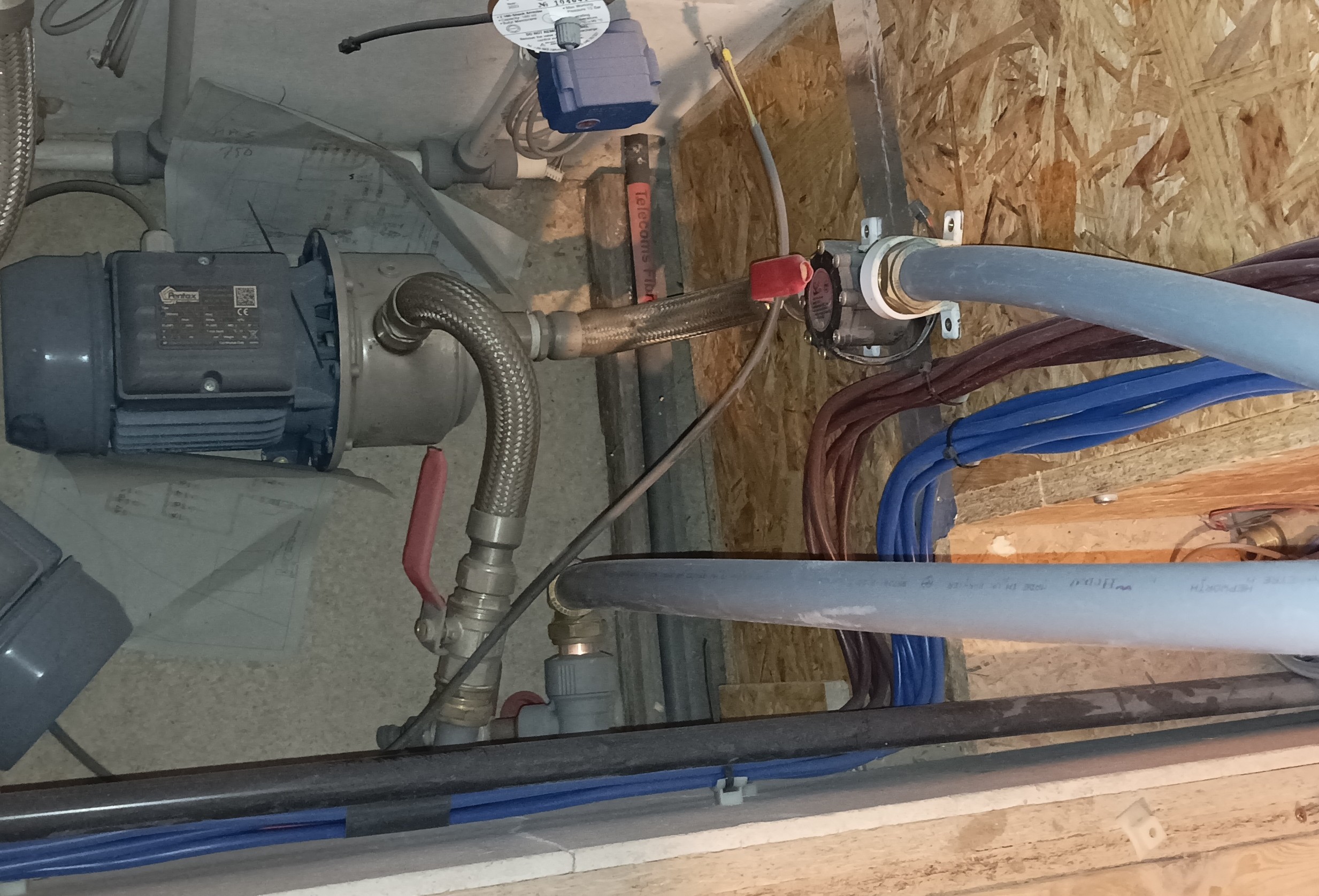
Hot Tank Pump
The next task to do, before we can test the circuit and all our connections, is to go around installing a pair of isolating valves at each tap-off point at each of the Bedrooms, Bathroom, Great Room and the end of the circuit in the Kitchen. In the Kitchen, we installed a short length of 15mm plastic pipe to join the two ends together, so that we can test the circuit for any leaks.
We then tested the plumbing by sticking the garden hose into the hot water tank and shoving the hose up the second 28mm extracting pipe inside the tank, to fill up the entire pipe circuit running around the house. We had to do that because the pump needed priming (filling it up with water) so that it has something liquid to suck upon. These kinds of pump do not run dry and cannot suck air, hence the need to prime the circuit with water and remove the trapped air inside. While the water was going in, we went to each tap-off point and check for leaks.
None so far ..
Once the pump is primed and connected to the electronic controller, we ran the pump at various speeds and pressures, to thoroughly test the entire system and make sure we don’t have any leaks. AND, We didn’t !!
The flow rate sensor was sending a pulse every litre that is flowing through the pump every second and at the highest power setting, we managed to get a 47litres per minute rate. And that is with a little 15mm pipe acting as the temporary bypass in the Kitchen. If we had a full size bypass, then the rate could be quite a bit faster!! And this is deliberately what we want to see, so that when there are sudden demands of hot water in two or three different locations, the pump can adjust itself to supply even more hot water and the human won’t notice the change, especially something like the shower.
This concludes getting the Hot Water circulating system commissioned and not having any leaks!