The last 9 days or so have been spent on processing a pile of Oak timber pieces and generating nine finished covers to hide the cut ends of the Larch cladding.
The rough oak planks were 3metres long, 29mm thick and a range of various widths from 100mm to 180mm. We wanted to end up with 27 planks, split into 2 sets of 90mm and 110mm widths and all at least 2800mm long (the longest length going up a corner).
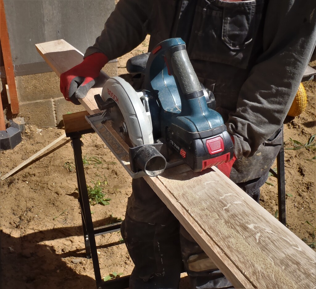
The first job was to ‘straighten’ each planks by slicing one edge using our track mains powered circular saw. This removed any wobbles and bends. Then after that, using the main table bench circular saw this time, and using the 2.4 metre fence to guide and control the width, we sliced these 27 planks into the 2 sets we needed.
So the next task was to set up the planer with its two input and output support tables, rigged up to our high air flow rate vacuum system to draw away the shavings and then proceeded to smooth off one side of all the planks. We do multi passes on each planks until we judge that there is enough of the surface planed to ensure that it will work reliably during the thicknesser stage. It is a compromise because we may find ‘more’ room to plane the other side and achieve at least one completely smooth finish. Any rough spots can be left hidden on the inner side of these Corner Covers.
As mentioned already, the second stage of the planing process was the thicknesser, and we worked our way through all the planks, flipping some over to remove more of the rough spots and eventually, we finished up with 18 smooth 110mm wide pieces and 9 90mm wide pieces.
Now after tidying away that machine, we brought out the table bench saw again, this time with the saw blade set to an angle of 45degrees and sliced the 18 planks (the 110mm wide set) to end up with one edge with a slope and a flat face of 90mm wide. This now matches up with the other set of 90mm planks.

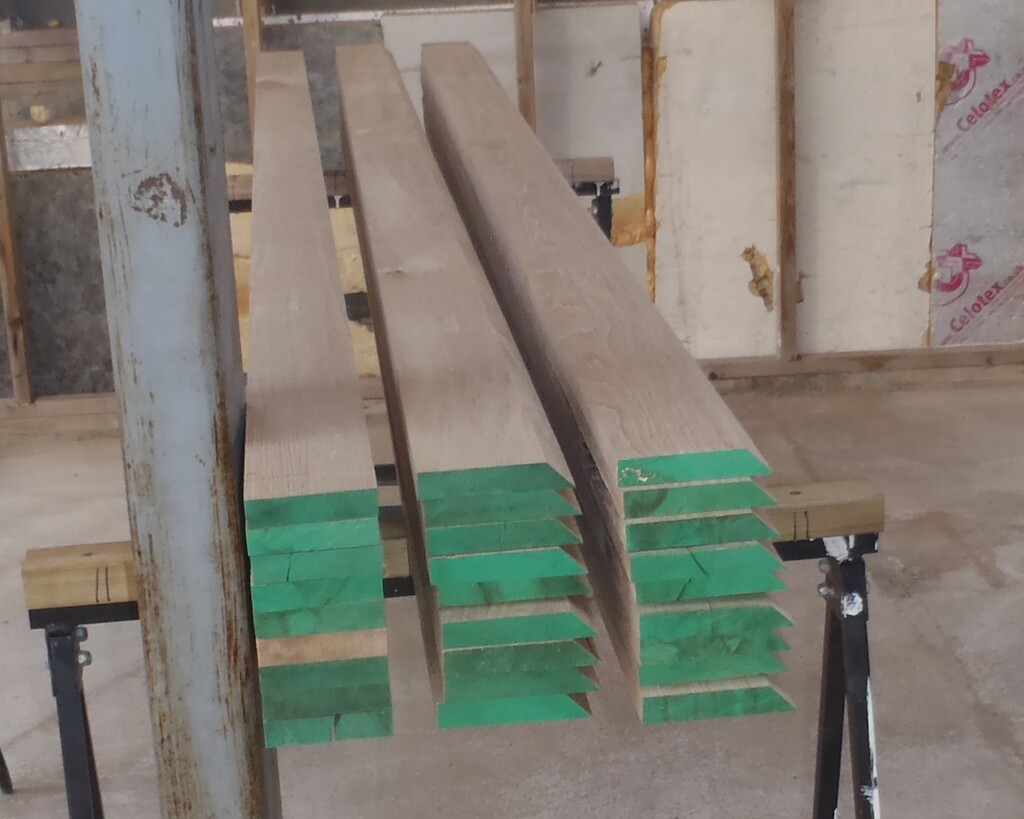
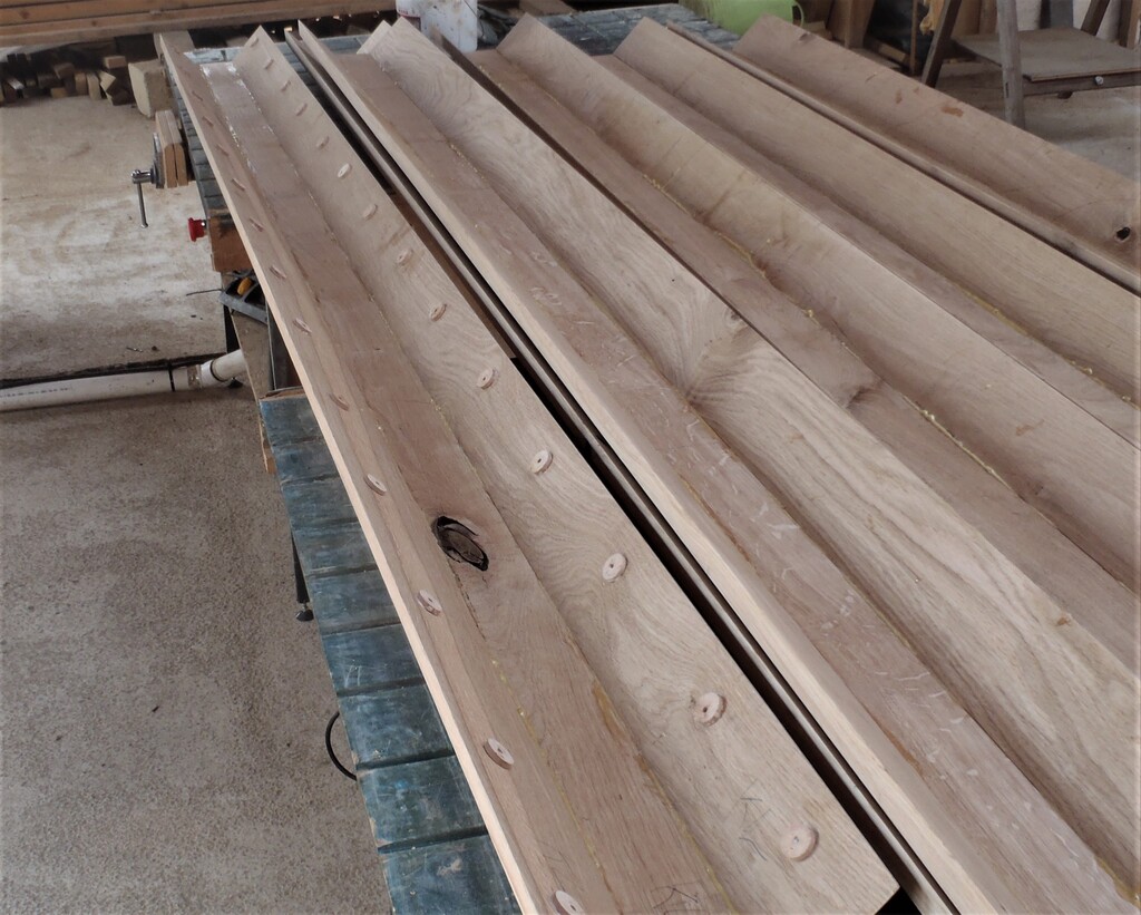
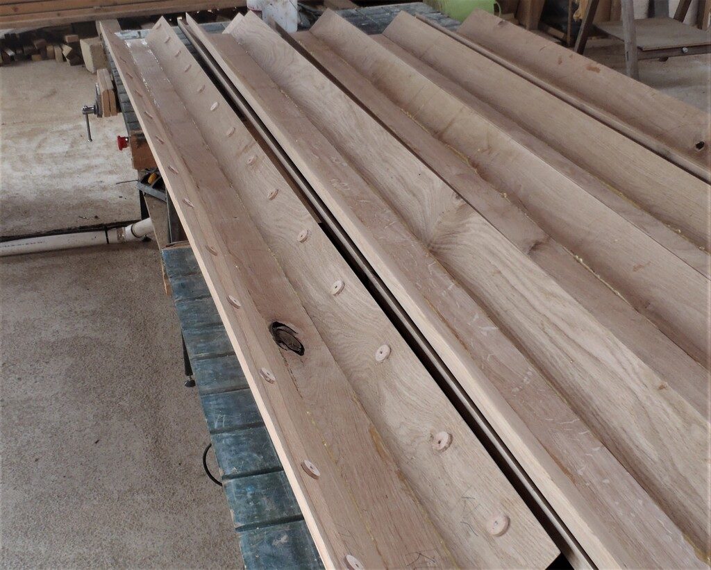
Parts-for-the-outside-corner-covers-Planed-and-Sawn
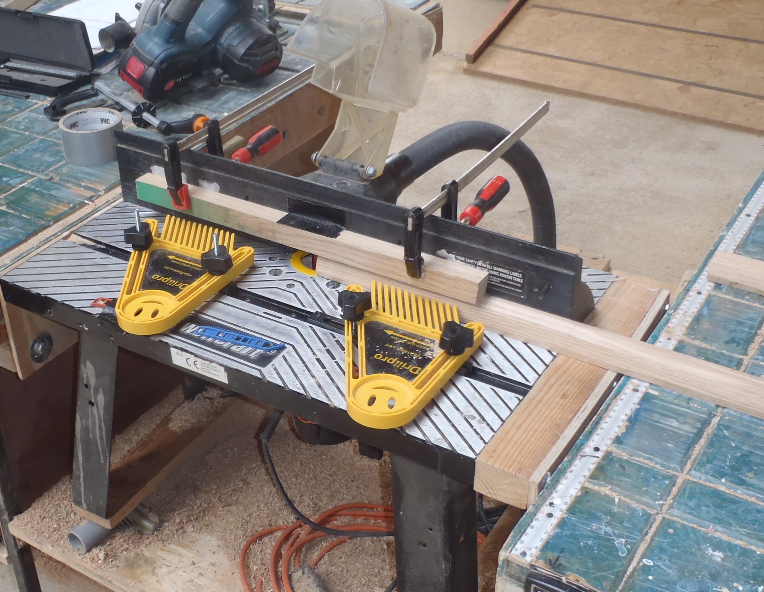
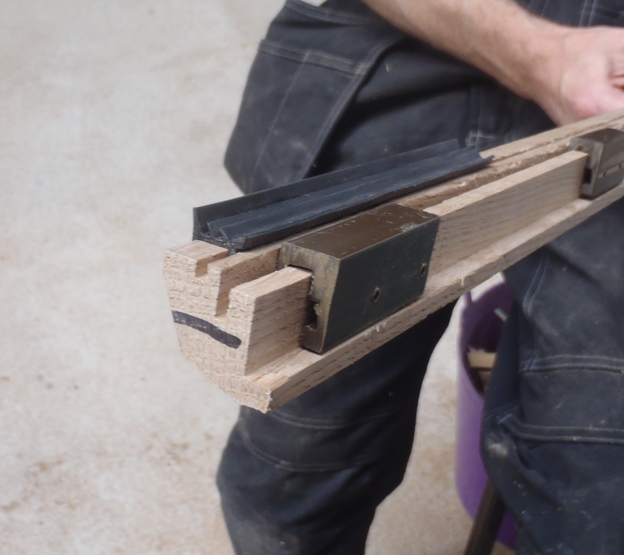
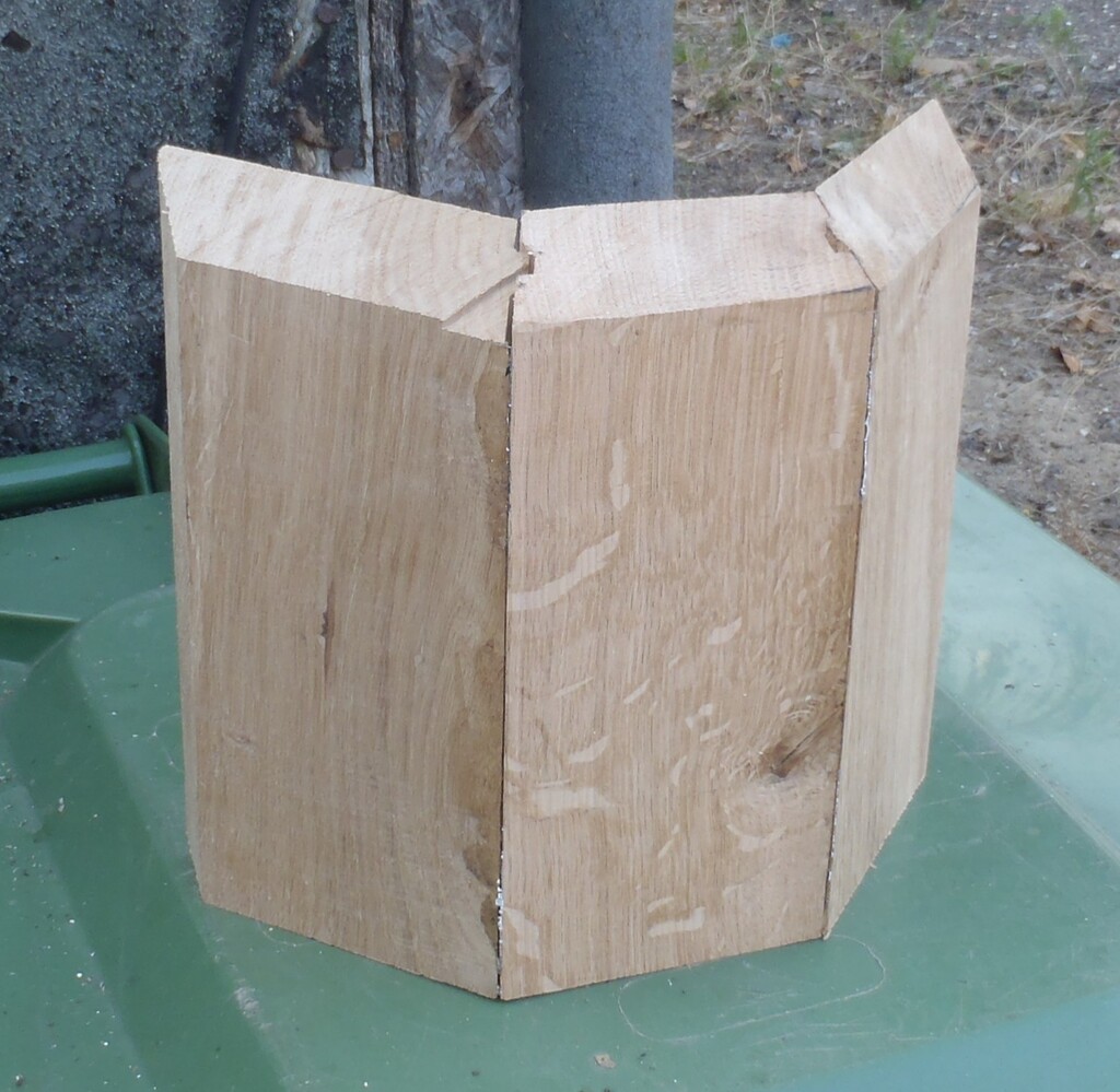
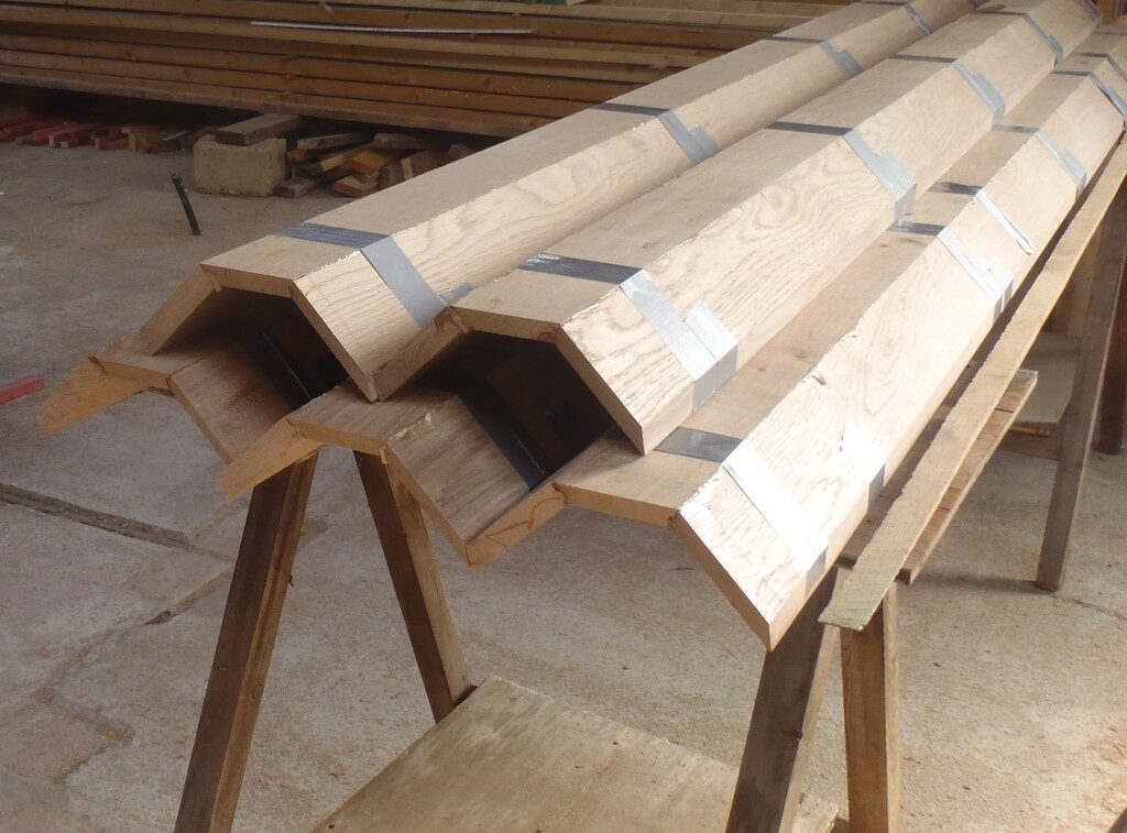
The next piece of machinery to come into play, is our router with the special 22.5° tongue and groove cutter bits, to create the joints to allow us to lock together the three planks (2 of the 110mm wide ones, fitted on to the 90mm middle piece) and form the half the octagon Corner Covers. We sorted out all the planks, checking for maximum length of finished surfaces and arranged 9 sets of three planks. We then knew which edge to cut and in the proper order. The last quick router task was to trim a small quarter rounded edge along the sharp 45degree slope to avoid future splinters and cracking.
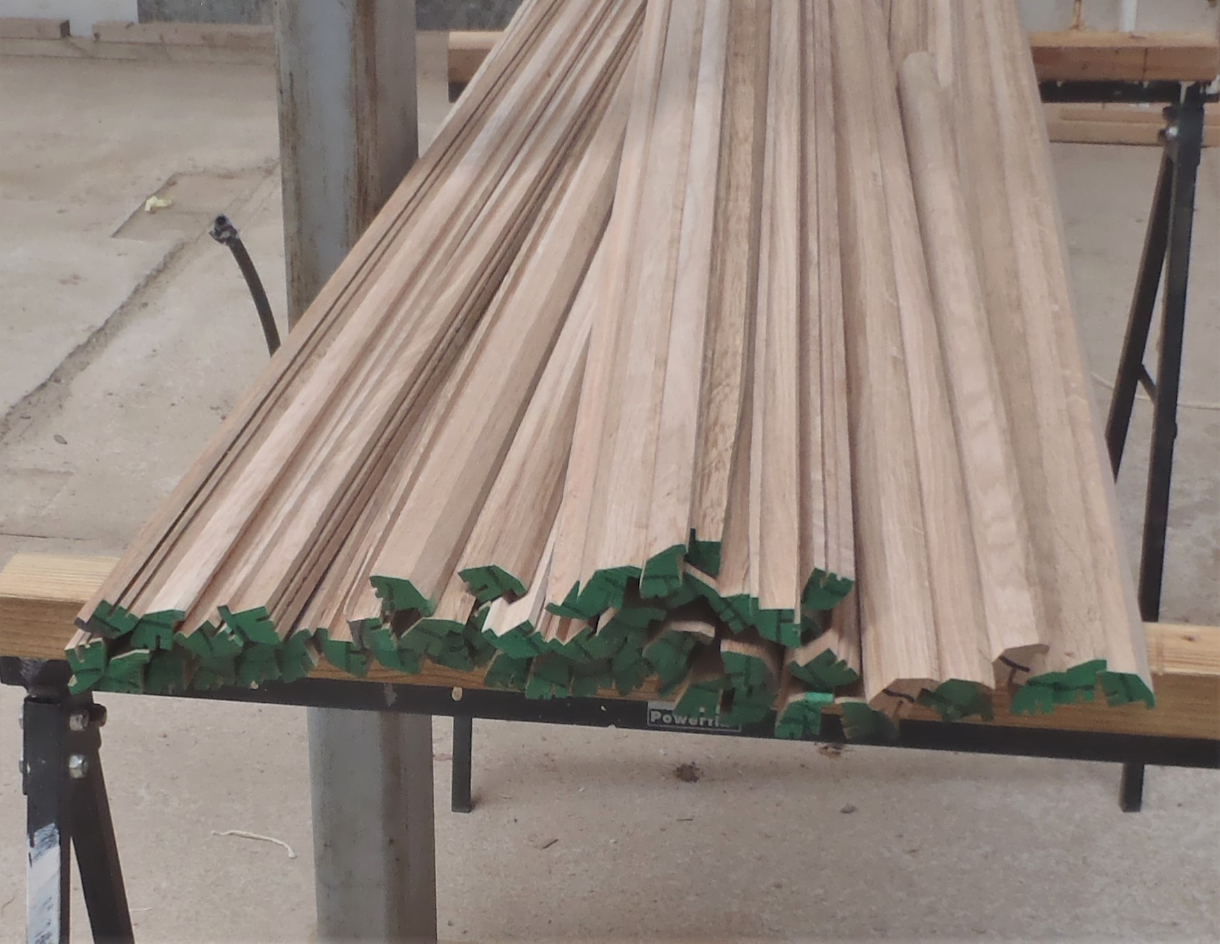
Parts-for-the-outside-corner-covers-Joints-made
The final sawing job is to slice little angled off both ends of each plank, the bottom ends (nearest the slates) had a 30degree angle and the top ends had a 45degree slope. But the precise length of each set of the three planks had to be measured from the real world (we walked around our house and measured all nine corners and wrote down the numbers.
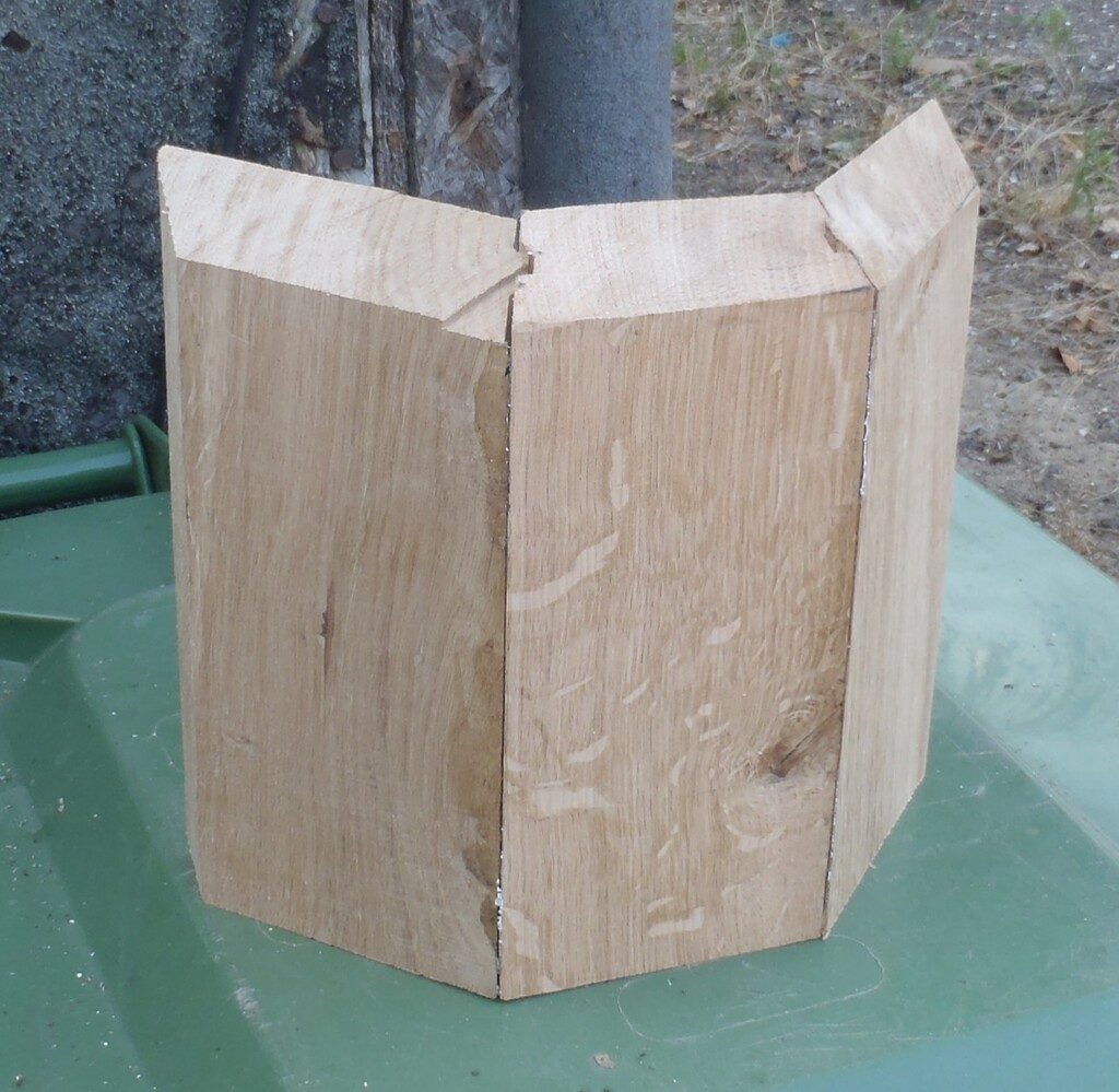
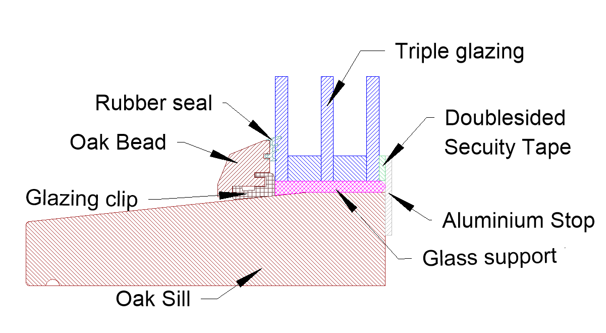
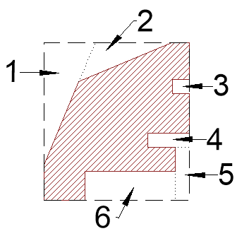
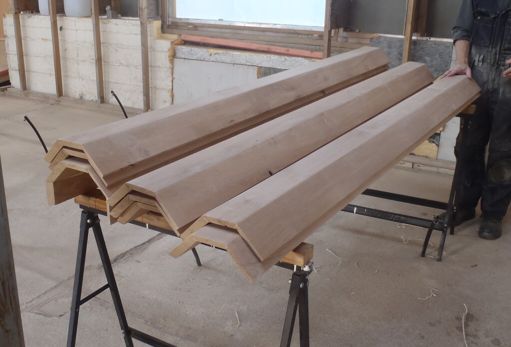
Sample-Outside-coner-section
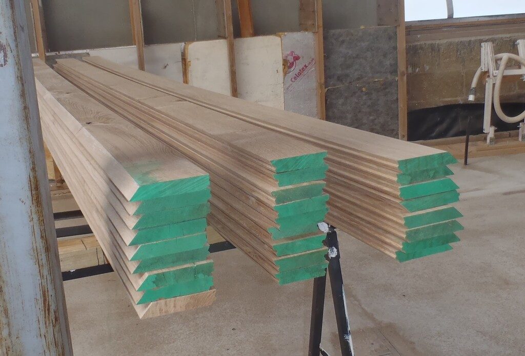
At last, we could, and did, stick together each set (using Polyurethane glue) for the joint and we used lots of duct tape to pull together the tongue and groove joints and held the shape tight while the glue cured.
Piles-of-glued-up-Corners-1
Piles-of-glued-up-Corners-2
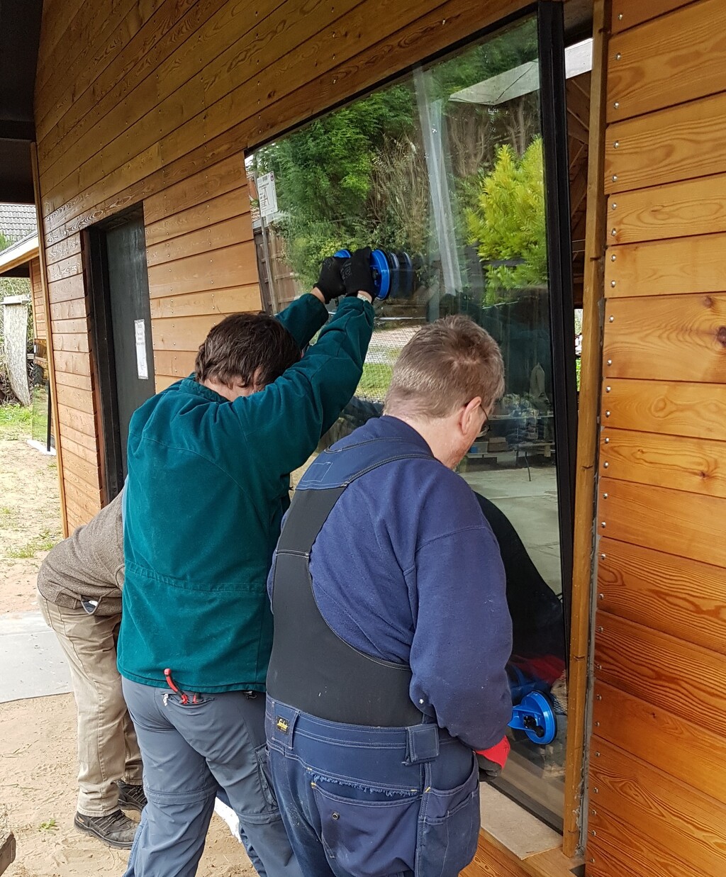
Then it was time to install them! Hurray!
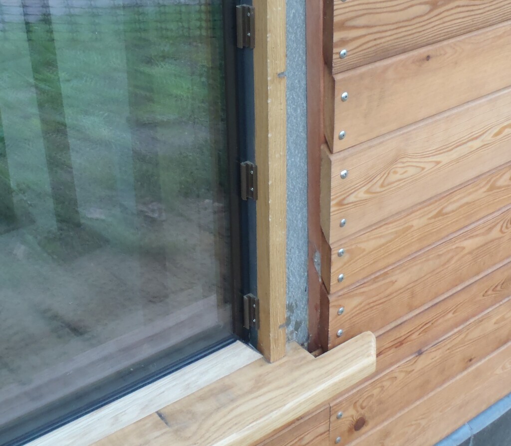
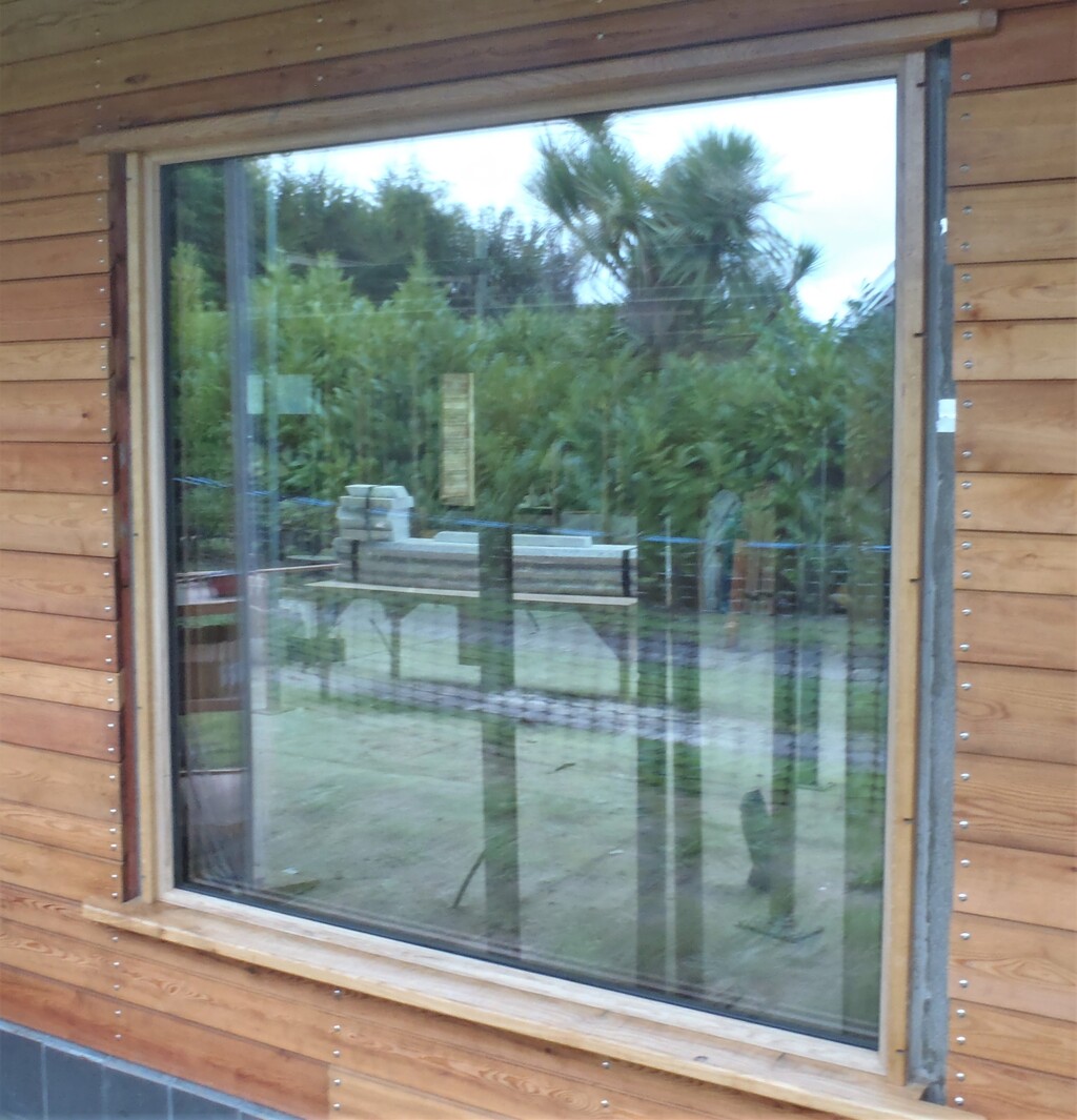
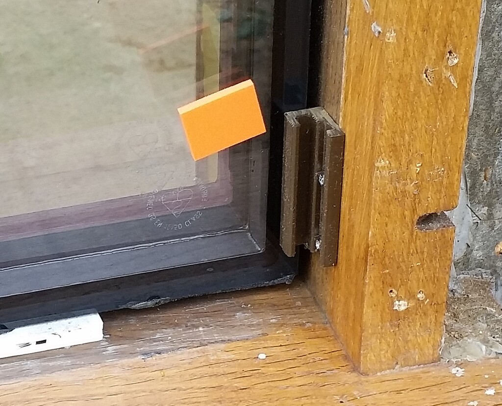
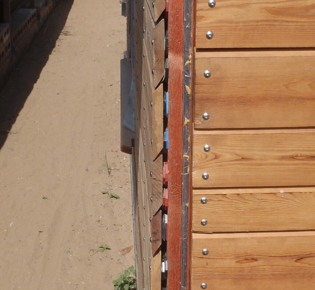
We started with the six easiest corners and thought we would tackle the nearest corner (the ‘OP’ one) to the Great Room which is where we are working these days, but only to discover that the wall along the ‘O’ section does a funny little wiggle at the bottom. The batten that holds up the Larch cladding had been bent outwards by the concrete blocks, without us spotting it. This meant that the Oak Cover has a large increasing gap between the Larch planks and the Cover piece (the Oak being nice and straight of course!). After skipping that corner to do the opposite corner, the ‘NO’ corner, which turned out to be much closer and even, we decided that we would make adjustments to the Larch cladding planks, rather than living with the gaping ‘hole’. So we undid the screws and pushed in ever increasing thicknesses of plastic spacers behind each Larch plank and then retighten the screws back down again. We use a long spirit level as our straight edge to achieve the proper and correct adjustment.
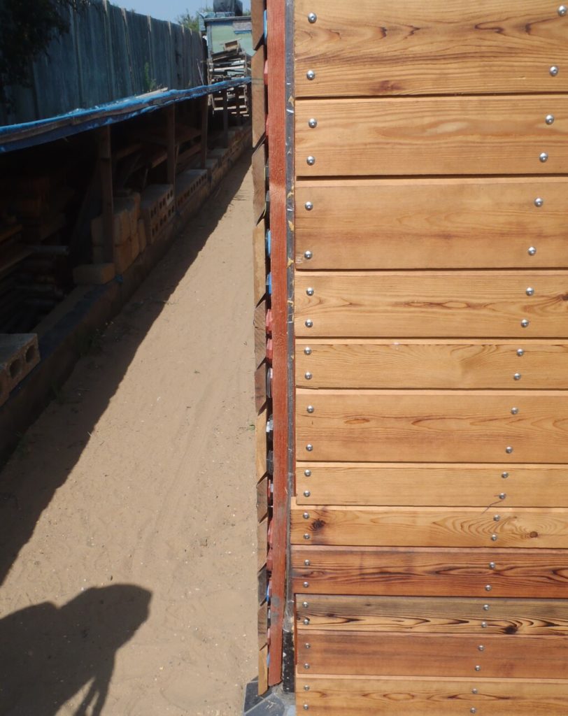
Straigtening-the-OP-Corner-1

Straigtening-the-OP-Corner-2
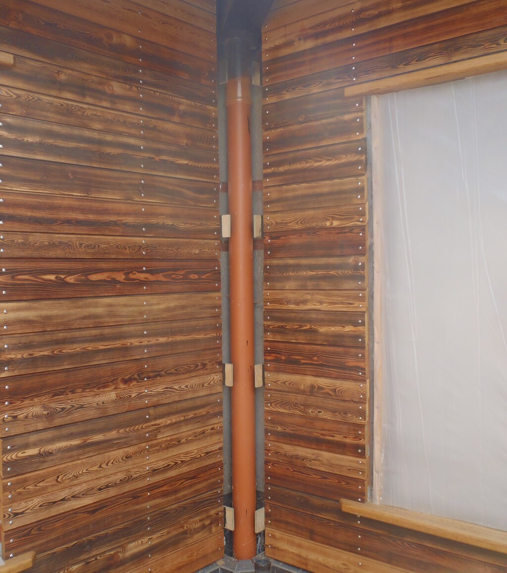
With this done, we now can go and make lots of wooden spacers to go behind the Oak Covers to allow plenty of air to circulate and keep everything dry and clean, to avoid any potential wet rot etc.
We decided to buy round wooden poles, and found a set of Eucalyptus broom handles on the web, an inch in diameter and about 1.5metres long. We got our drill press machine out and rigged up a little holder to hold short lengths of the round rods, and drilled a centralised clearance hole down the middle. We then slice the rod up into lots of 5mm thick discs, thus made our spacers with a predrilled hole, ready for going between the Oak and the Larch and screwed down.
Now the next task was to find an old waste length of oak strip and mark off distances of 200mm up the length and guide us to try and keep an regular spacing for the fixing screws. But before that, we snapped together a metal placement template for the drilling of the clearance holes in the Oak, positioning the template on the 45degree slope and get consisted alignment up all the Corner Covers.
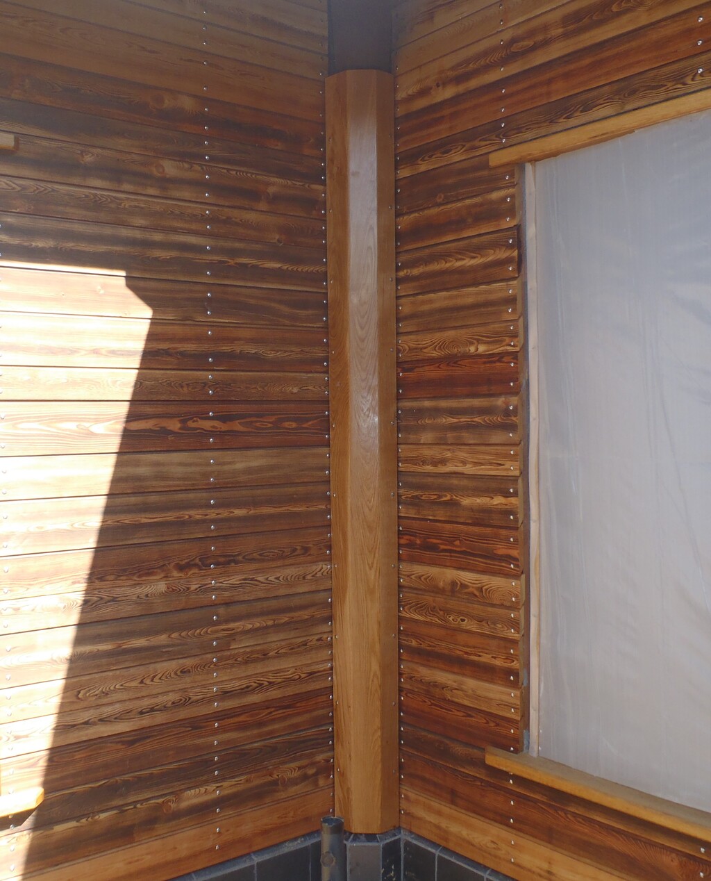
So the procedure for putting up these Covers, was to drill the first clearance holes at the bottom, 75mm off and then screw it on to the corner. Then using the marked guide stick, drilled clearance holes at approximately every 200mm, only making adjustments to ensure that the fixing screw sinks into solid portions of the Larch timber. Then taking the Cover piece down again, taking it indoors and glue on our little wooden discs using 5 minute PU glue. While that was curing, we took out the next corner to repeat the process of doing the clearance holes. After that, the Oak Cover piece would go back outside to lay on a set of trestle tables and proceeded to get a thorough coating of the timber oil treatment, on both sides but most especially the hidden interior side. While that was soaking in and dripping excess off, we got on with the third corner in doing the clearance holes. Eventually, the oil had soaked in enough for us to handle it and actually install the first corner piece which we did!!
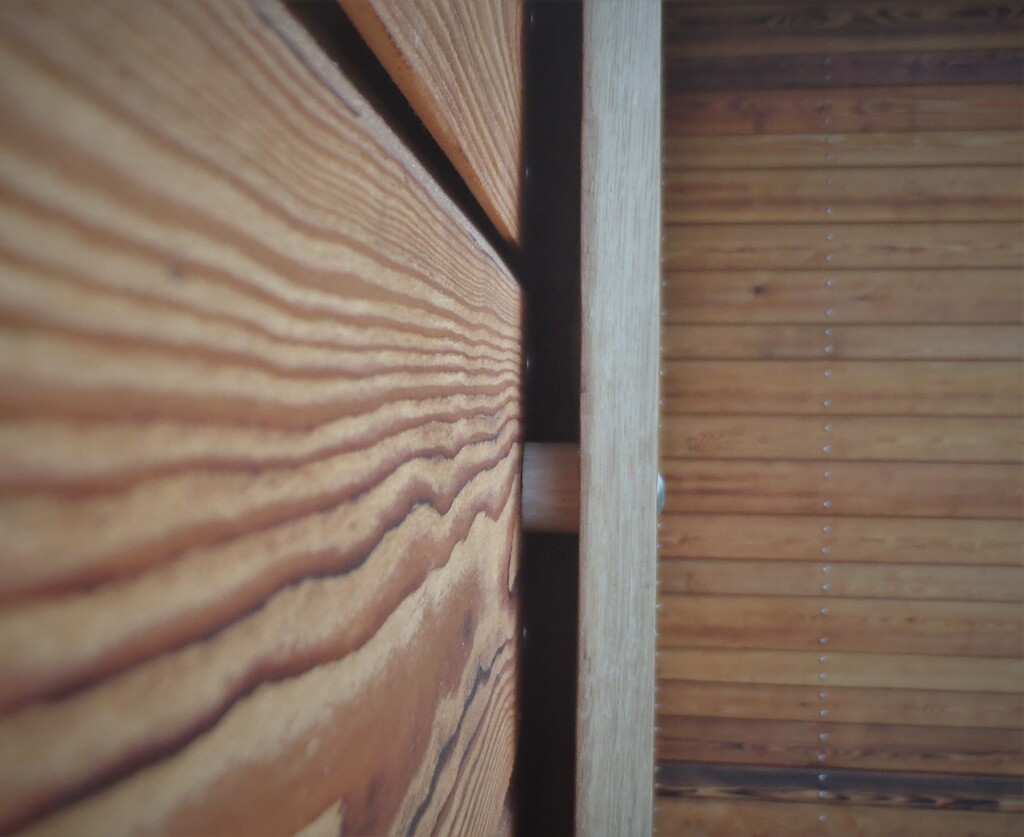
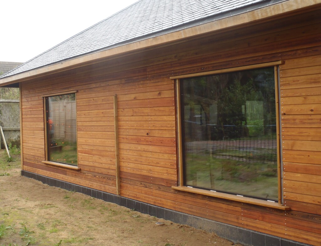
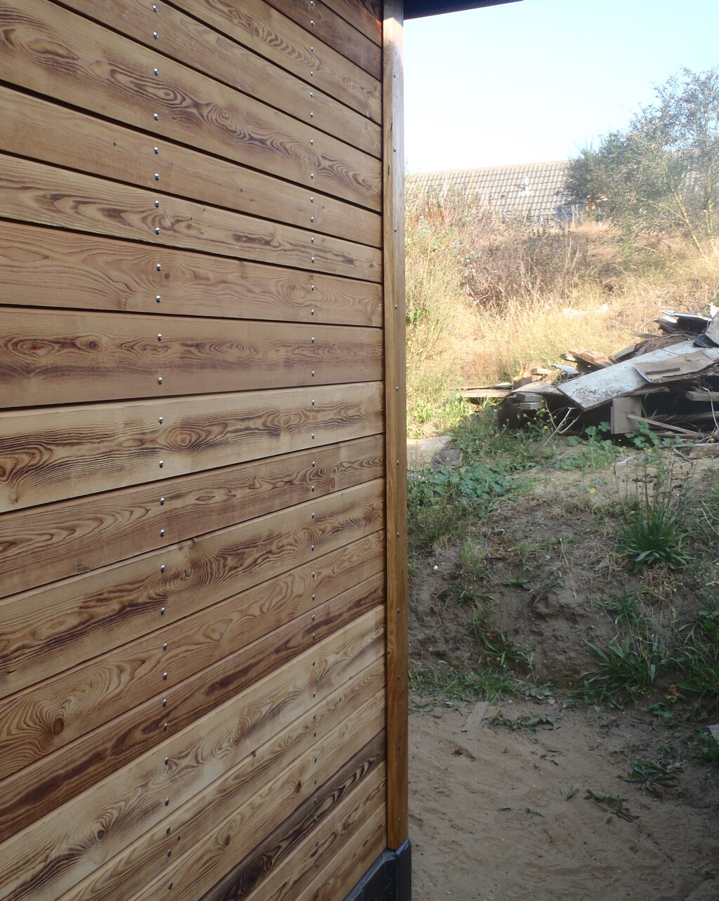
Corner-with-spacers-attached

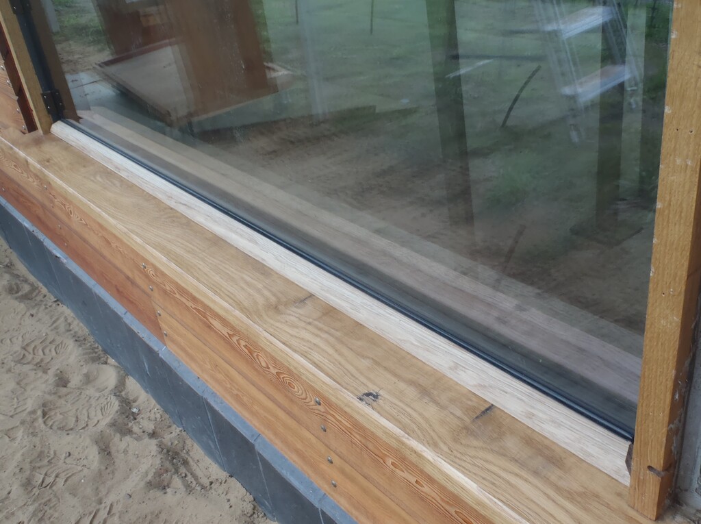
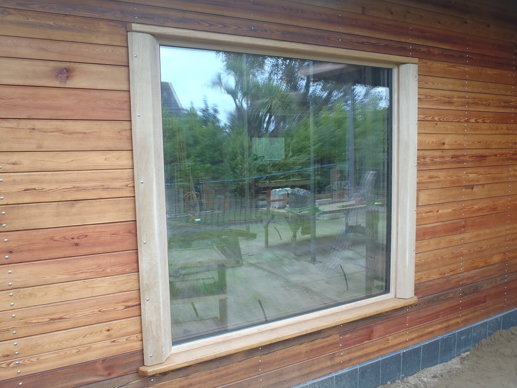
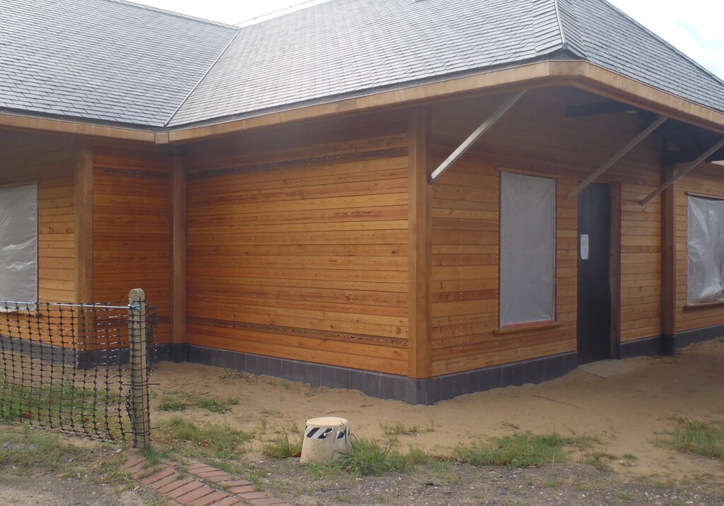
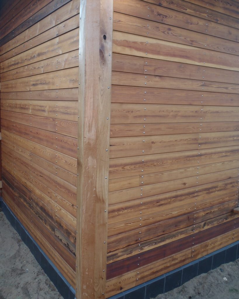
The-Staight-OP-Corner
As you can imagine, this logical collection of programmed steps was repeated several times over until we got all nine corners done.
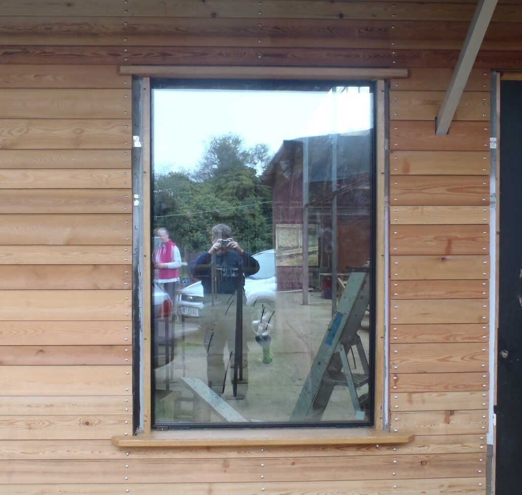
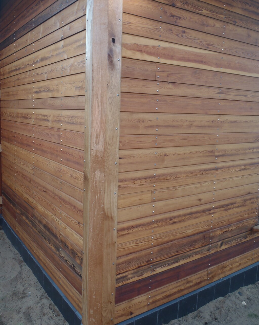
The-AP-Corner-cover
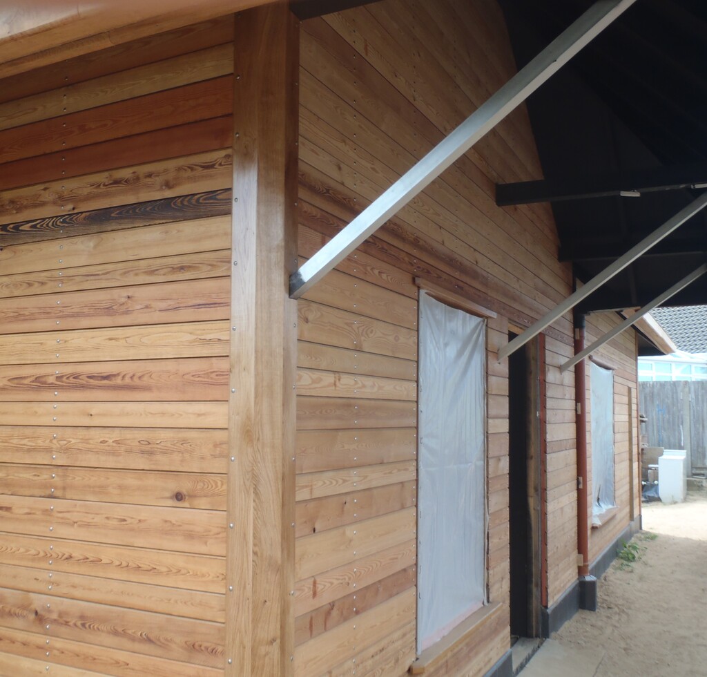
The last three corners, two on the Front Porch and one on the Side Porch, had a little adjustments made to the tops of their covers, to allow us to go around the main support beam sticking out the house, and for the Side Porch, an additional adjustment to clear the diagonal metal bracing arm too.
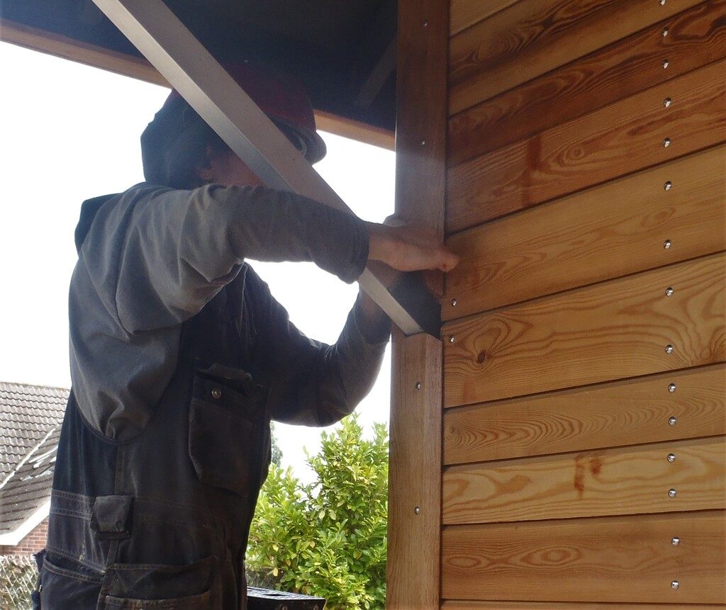
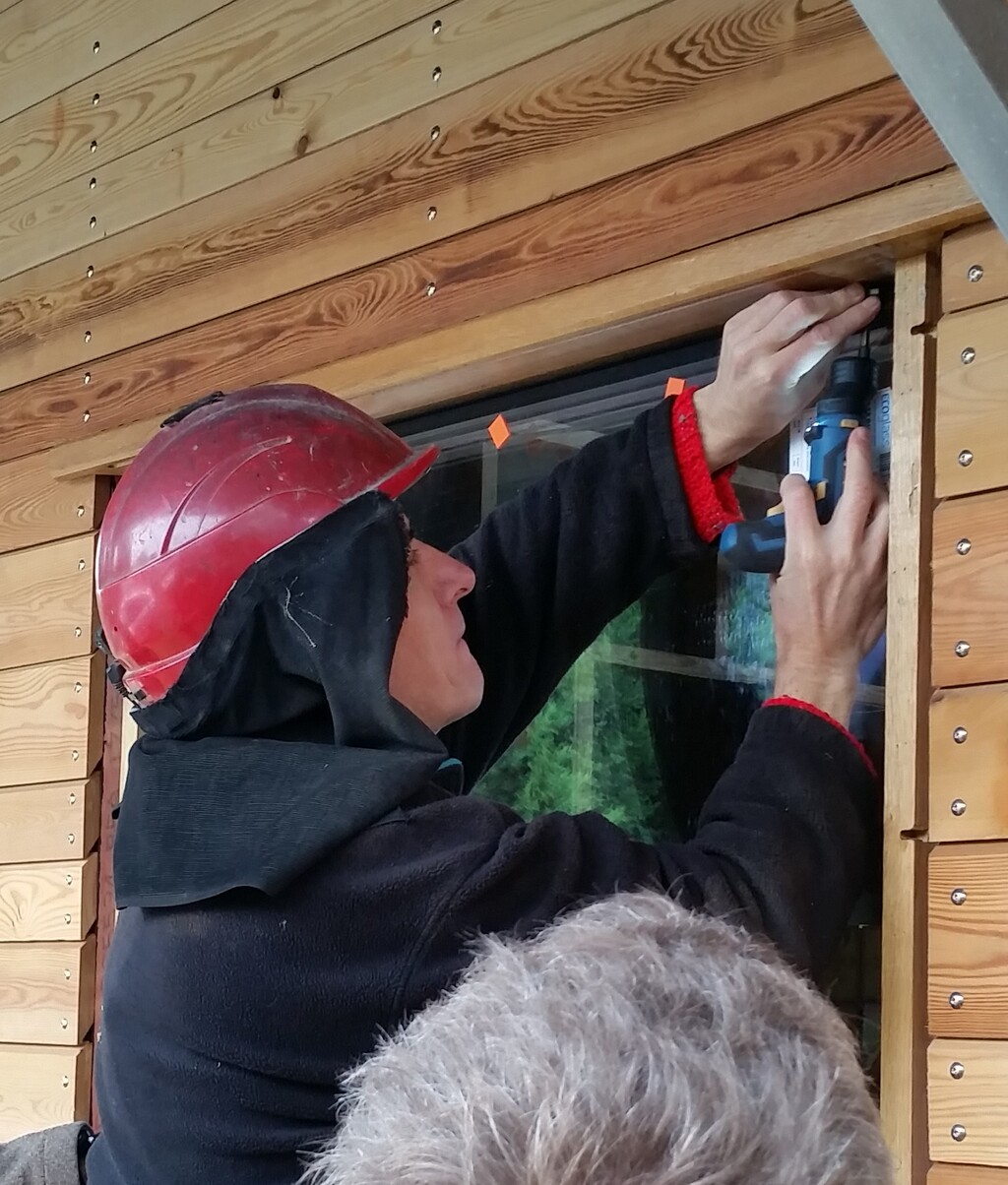
Shaun-tightening-the-last-screw

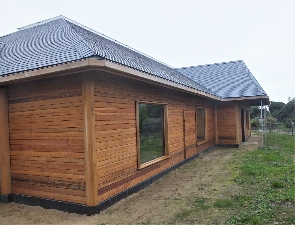
The-EH-Corner
This is the complete process of taking rough sawn oak timber and ended up with nine finished Oak Covers, all in about 9 days. Not Bad!
Now we repeat the whole process over again, but this time, for the Inside corners, to cover up the plastic downpipes plus our odd one in the middle of the ‘H’ wall. But that is another story and next week’s work!! Actually, We have already started the process and we have got out all the 2.6metres oak timber pieces and sliced them up into the required 26 planks, and even got most of the planing done too! More in Next week’s blog report!