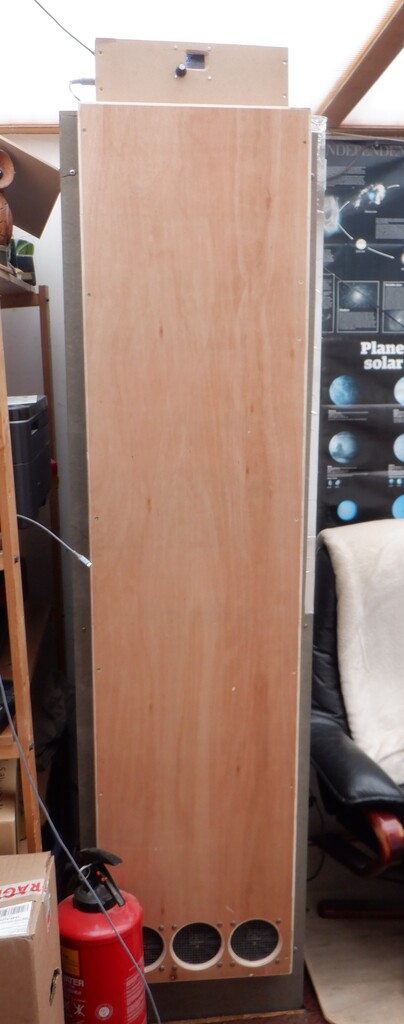
Here we are .. just to the start of Winter .. and we are having to service our homemade Storage Heater, to make it fully functional again. Also, we are taking the opportunity to upgrade the control board as we had a proper PCB made earlier in the year when we did some lighting modules so we included a design to allow us to put on a new larger micro-controller chip.
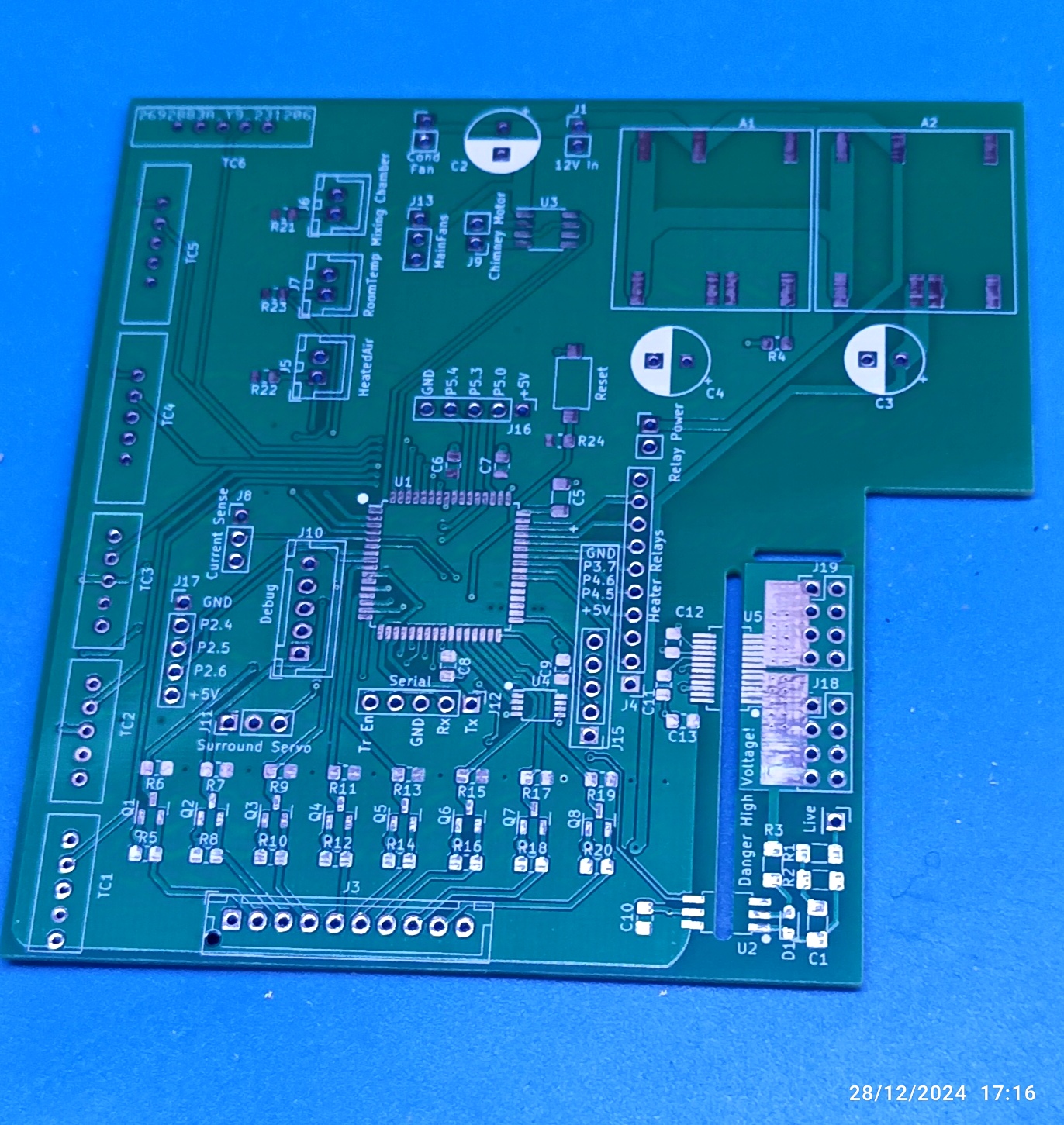
New Stoarge Heater control PCB
We undid all the wiring and devices from the old control board and populate the new PCB with those, plus some new extra ones too.
There were some minor corrections needed to be executed on the PCB and other slight modifications but we now have a new working control board without the forest of looping wires shooting all over the place.
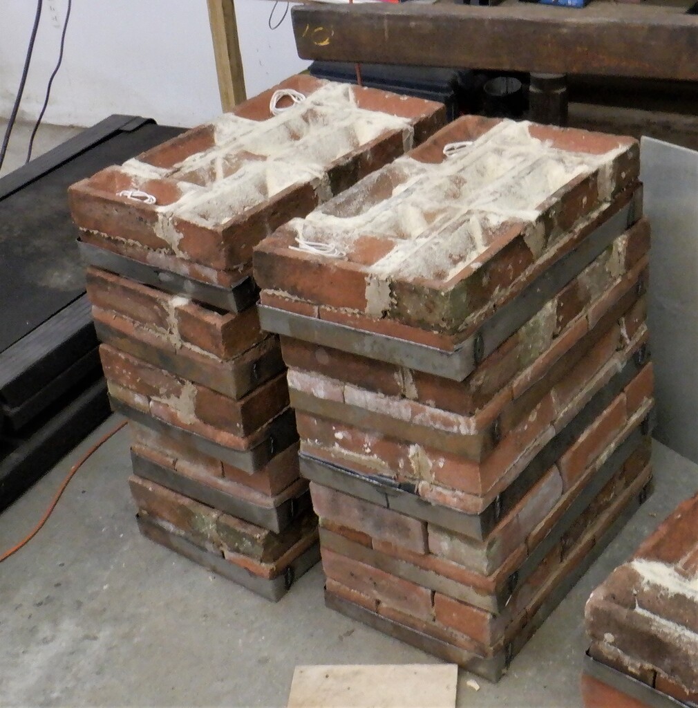
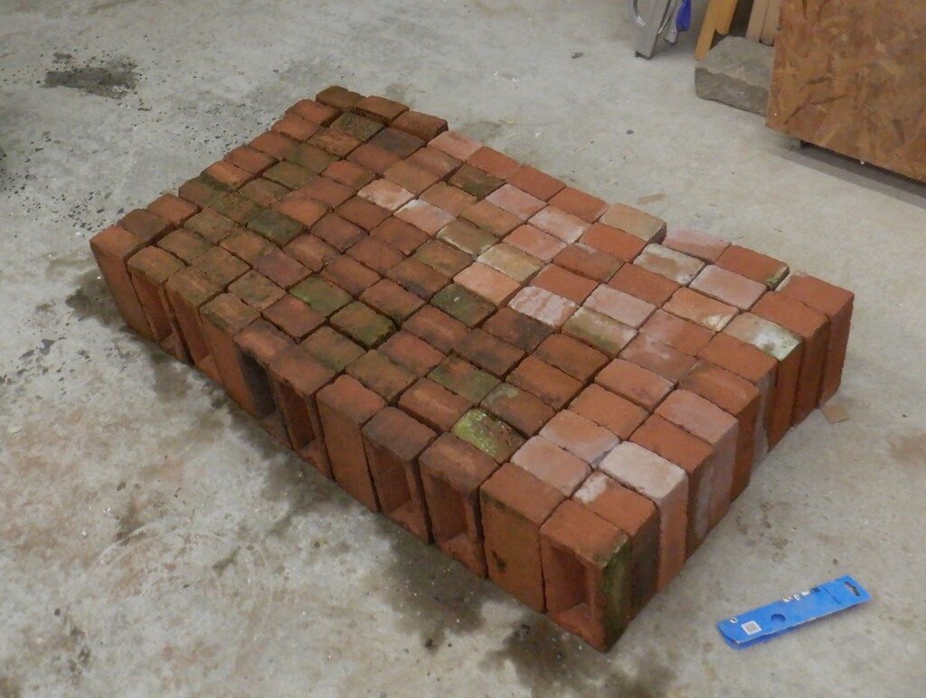
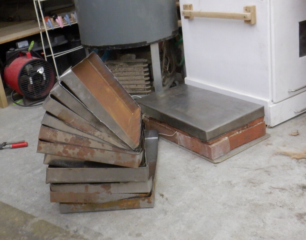
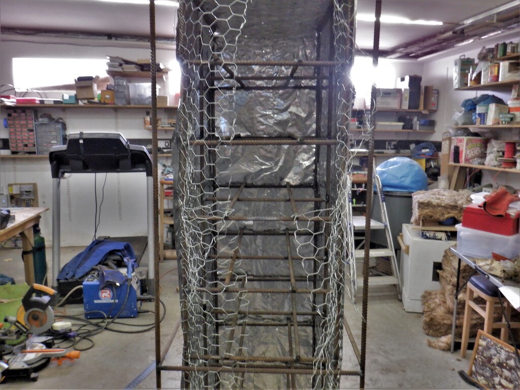
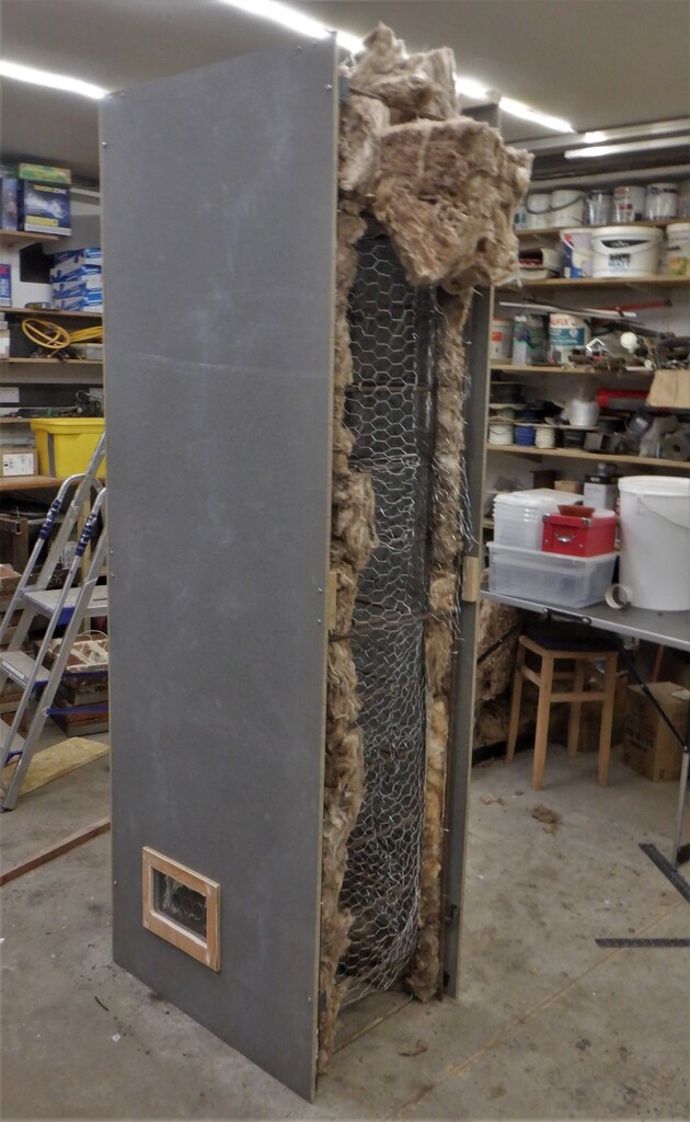
The next job is to get access to the trays of bricks so we undid the front panel, loosen the wire mesh, carefully picked off the glass wool and untangle the inner wire mesh as well and bent them open to the sides. At this point, we discovered that some of the insulation was very fragile and crumbled when we touched the wires coming out of the trays, especially the top ones.
So, it was a case of replacing all the wiring with better high temperature resistant insulated wires which we found on the web. We bought two rolls of 12metres of three layers; one woven glass fibre on the outside, a middle layer of Mylar and an inner layer of more woven glass fibre, protecting a 0.75square millimetres of 10 stranded copper wire. The whole wire is rated for 500°C !!
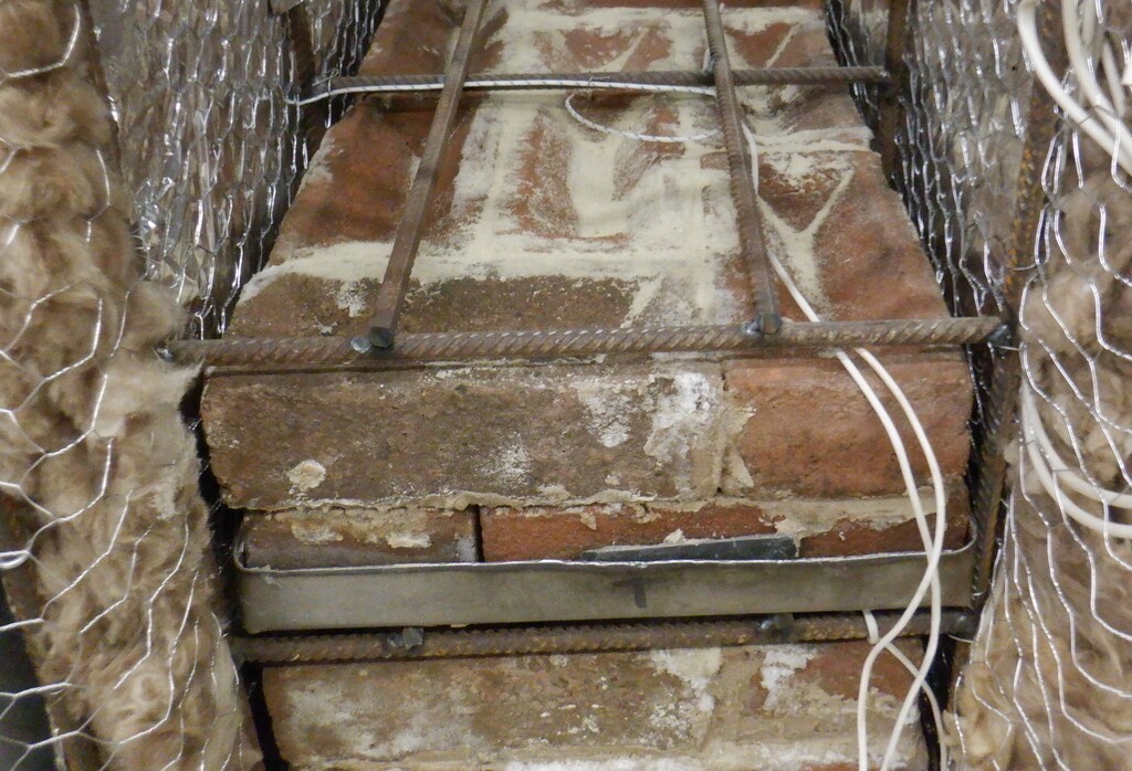
We also noticed that the spade terminals plugged onto the elements inside the bricks, were not tight anymore and this has caused corrosion, probably caused by electric arcing damaging the surface. So we needed to solder the new wires directly on to the terminals on each element. This meant finding a high temperature solder and it turned out to be a silver copper alloy that has a melting point of 750°C to 800°C which is high enough for our requirements! We bought a tiny little syringe weighing just 5grams costing £10!! Silver is not cheap!
This syringe also has a special flux mixed in with the silver and copper particles.
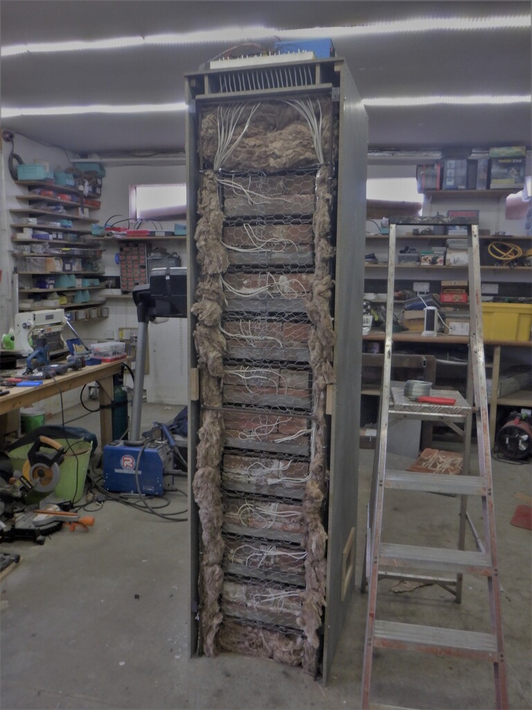
Once these items arrived in the post, we proceeded to lay in the new wires, a pair for each tray, going out sideways and then up to the top of the cabinet and then up into the control board area where they were terminated with a solid caps and then screwed into a line of terminal blocks. One thing we discovered was that one of the rolls was only 11metres long and not 12metres!! What Cheek of the manufacturer! We had to borrow a short length of our old wiring for the last section going up to the top of the cabinet which is fortunately outside the hottest zones. So should be ok.
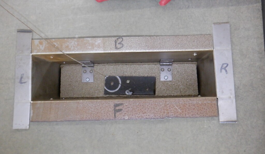
Next, by pulling each tray out a few inches, we scrubbed the two iron tabs of the elements using a ‘scotch-brite’ wheel, to clean up the corrosion and rust.
We then expose several inches of the wire, twisted the strands together and then poke the end through the little hole in the middle of the tab and wrap it around twice, before arriving back to the incoming wire where it was twisted together. We had some old flux which we revitalised and applied a blob to the contact area and using a miniature blow torch using liquid propane gas, heated up the tab until it started glowing orange hot. It said on the web that bright red for iron has a temperature of about 730°C and orange is a temperature of 930°C which is high enough to melt the silver solder.
We did the second tab the same way and then to make sure that we got a good soldered connection, we measured the resistant between the two wires up on our control board and if it reads approximately 67ohms which is the internal resistant of the element themselves, we therefore got a good connection.
We repeated this task for the next seven trays (one of them had a resistant of 98ohms which meant the soldering didn?t work terribly well so we redid it again).
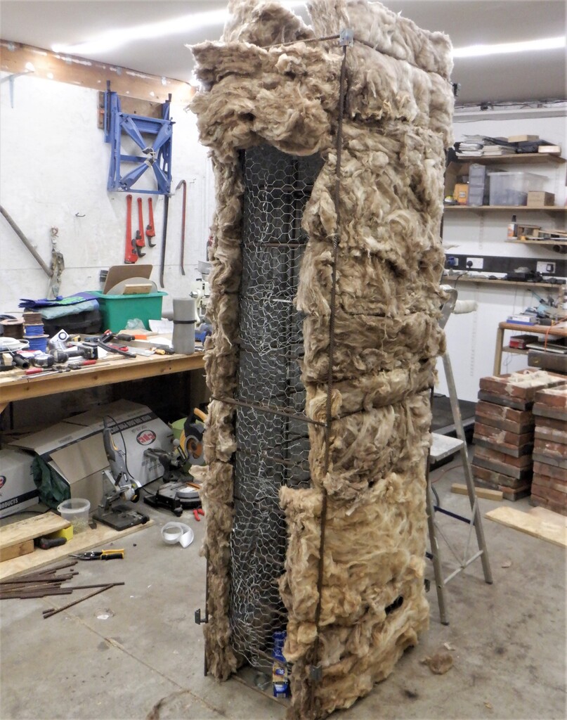
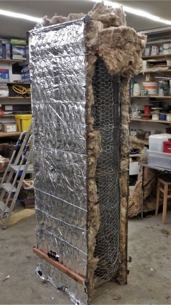
Now that is all done, we could reassemble the wire mesh and put back the glass wool. But before putting on the outer layer of the wire mesh, we got some more glass wool and thickened up the two outer vertical edges and also folded a double thick layer for the upper 6inches above the trays of bricks. It was showing signs of being rather patchy.
This will hopefully help reduce various hot spots on the cabinet, especially near the top on the right side. We will see!
The final wire mesh was inserted into place and after double checking all the electrical connections to each tray again, we put the front panel back on.
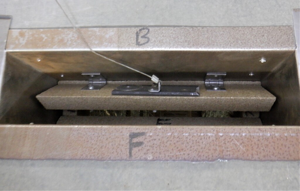
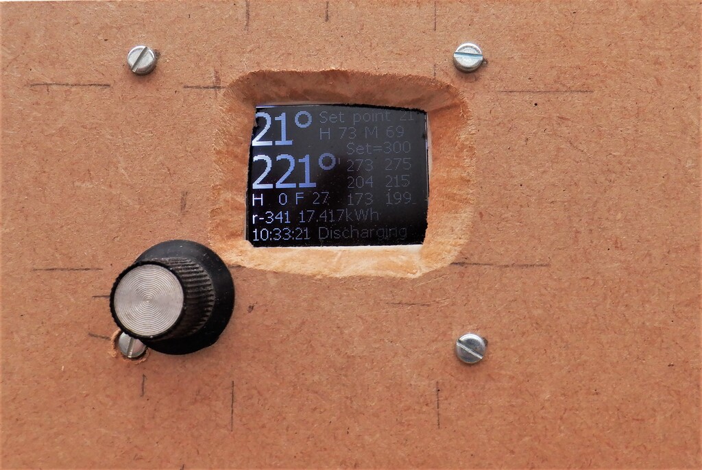
The new micro-controller was tested and the software was modified so that we can now switch on any of the eight trays. The display is working, the menu button and selector is working, the mains electricity sensor to measure the current is working, the 50hz signal is being picked up, the motor for the chimney flap is working and all six thermocouple probes are reading ok too. We double checked all the electrical connections at the relays and the row of terminal blocks and we did discover a left-over wire link in the back of the last terminal block. It was reading 0ohms between the live and neutral lines and only after leaning over and cranking one’s head (a very tight gap between the ceiling and Storage heater) to see behind the terminal block, we could see this rather hidden link! The next test was to measure the resistant of each circuit after all the relays were told to switch over to the ‘on’ position and we discovered another problem. It seems that we may have burnt out the internal contacts as most of them shows very high resistant levels so we had to order a replacement eight-way relay module.
This duly arrived within a day and we did the laborious job of unscrewing all the connections to release the wires off the old module and then slide in the new one, putting all the dozens of wires back.
After testing the new relays, which are all working just fine, we proceeded to a full test where we set the temperature to a low 100°C and set the clock so it thinks it is in Economy 7 mode.
It switched on five of the eight trays at a time, using the pattern of on, on, off, on, on, off, on, off for tray 1 through tray 8 respectively. Then, every five minutes, it would rotate this pattern, one tray position, around the eight trays so that all the trays would eventually get equal amount of charging.
And ..
All is successful! It got to the required temperature and stopped charging in just under an hour. Yippeee!
Now we can reset the clock to the correct time and set the target temperature to 300°C and leave it to run overnight.